Tag: 5-Axis Simultaneous Machining

  • Master Wang Reveals: Full-Process Programming for Multi-sided Parts with Angle Heads in Siemens NX –

    📝 Key Takeaways: Master Wang provides a practical walkthrough of full-process programming for multi-sided parts using angle heads. From roughing to finishing, he covers using a D10 tool for finishing passes on bottom faces and side walls. The core focus is on analyzing how to address common challenges like unmachined areas and toolpath deviations by “patching” regions, adjusting toolpath strategies (bounding box/contour), and precisely controlling stock allowance and cutting layers, thereby enhancing machining accuracy and efficiency.

    [VIDEO_HERE]

    Listen up, folks! It’s me, Old Wang, Master Wang. Today, we’re cutting the fluff and diving straight into full-process programming for multi-sided parts using angle heads. You can read all the books you want, but without a decade or more spent by the machine, you’ll never navigate the real-world pitfalls. Angle heads are phenomenal for multi-sided machining; they can circumvent many fixturing challenges, allowing you to machine multiple faces in a single clamping setup, which significantly boosts efficiency. Today, we’ll go from roughing to finishing, dissecting the ins and outs of every step.

    Strategy Planning: Programming Logic for Multi-Sided Parts with Angle Heads

    Why Angle Heads Are Crucial

    Angle heads, especially those used in 5-axis simultaneous machining, offer the primary advantage of extending tool reach. Think about it: for a complex part, how many times would you have to refixture it on a 3-axis machine to machine multiple faces? Each clamping operation introduces cumulative errors, making high part accuracy almost impossible. An angle head allows you to tackle side faces, angled surfaces, and even undercuts that would typically require multiple fixturing setups, all within a single clamping operation. This not only saves time but, more importantly, significantly improves machining accuracy and surface finish. Don’t just look at the tool cost; when you factor in the total cost, it’s absolutely worth it!

    Overall Machining Process Breakdown

    There’s a method to the madness, and programming is no different. For these multi-sided parts, we can generally break it down into these steps:

    1. Roughing: Quickly remove the majority of stock allowance with a large tool.
    2. Semi-Roughing: Refine the shape after roughing, preparing for the finishing pass, especially for corner cleanup.
    3. Corner Cleanup / Rest Milling: Clean up the remaining stock in corners and radii after semi-roughing.
    4. Finishing Pass on Faces: Perform finish cuts on all flat surfaces.
    5. Finishing Pass on Side Walls: Perform finish cuts on all side walls.
    6. Finishing Pass on Bottom Face: Perform finish cuts on the bottom face.

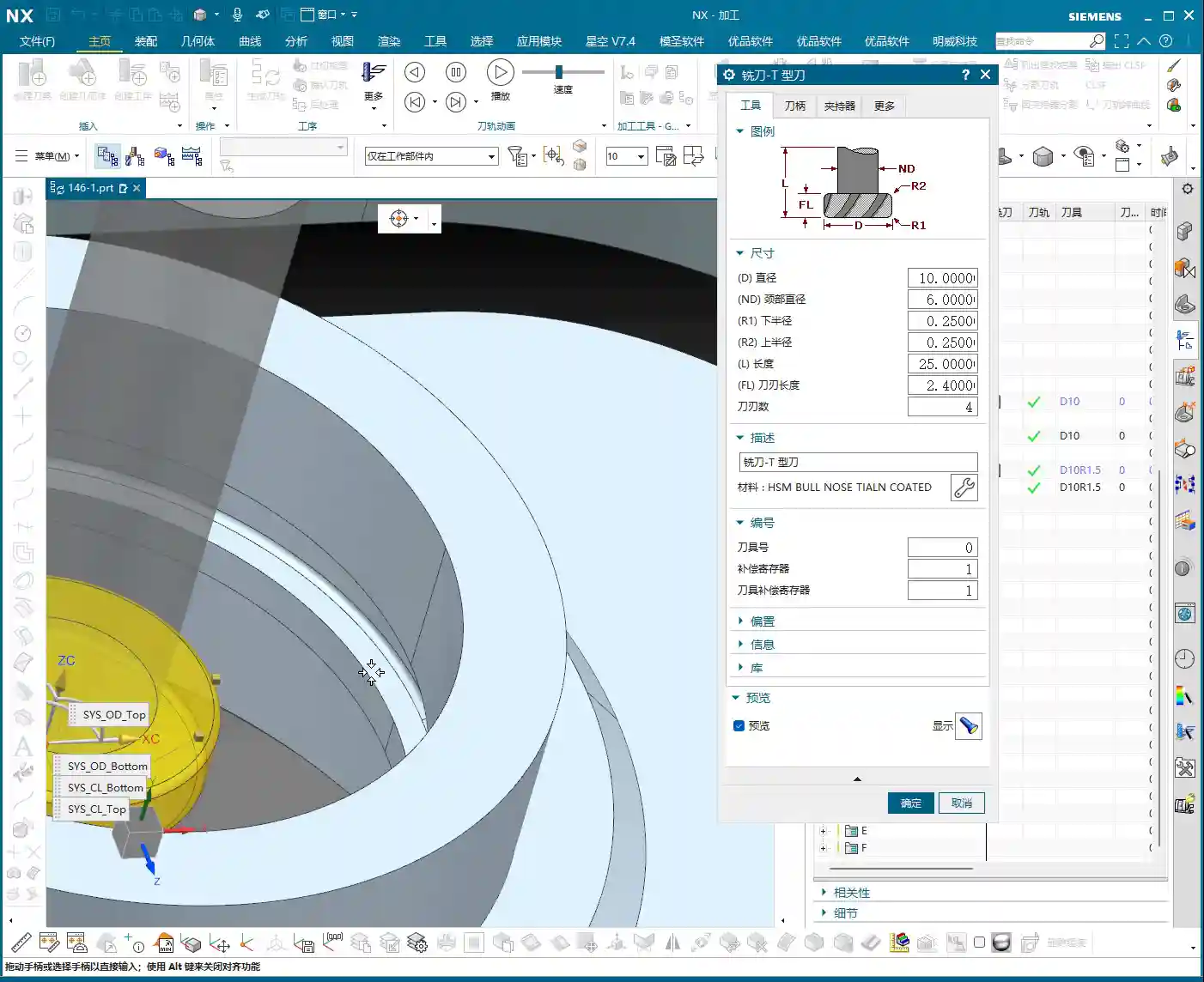
    Our focus today is on the application of angle heads, so many operations will revolve around this, particularly the use of the D10 tool, which is our primary tool for subsequent finishing passes.

    Practical Exercises: Progressive Toolpath Refinement

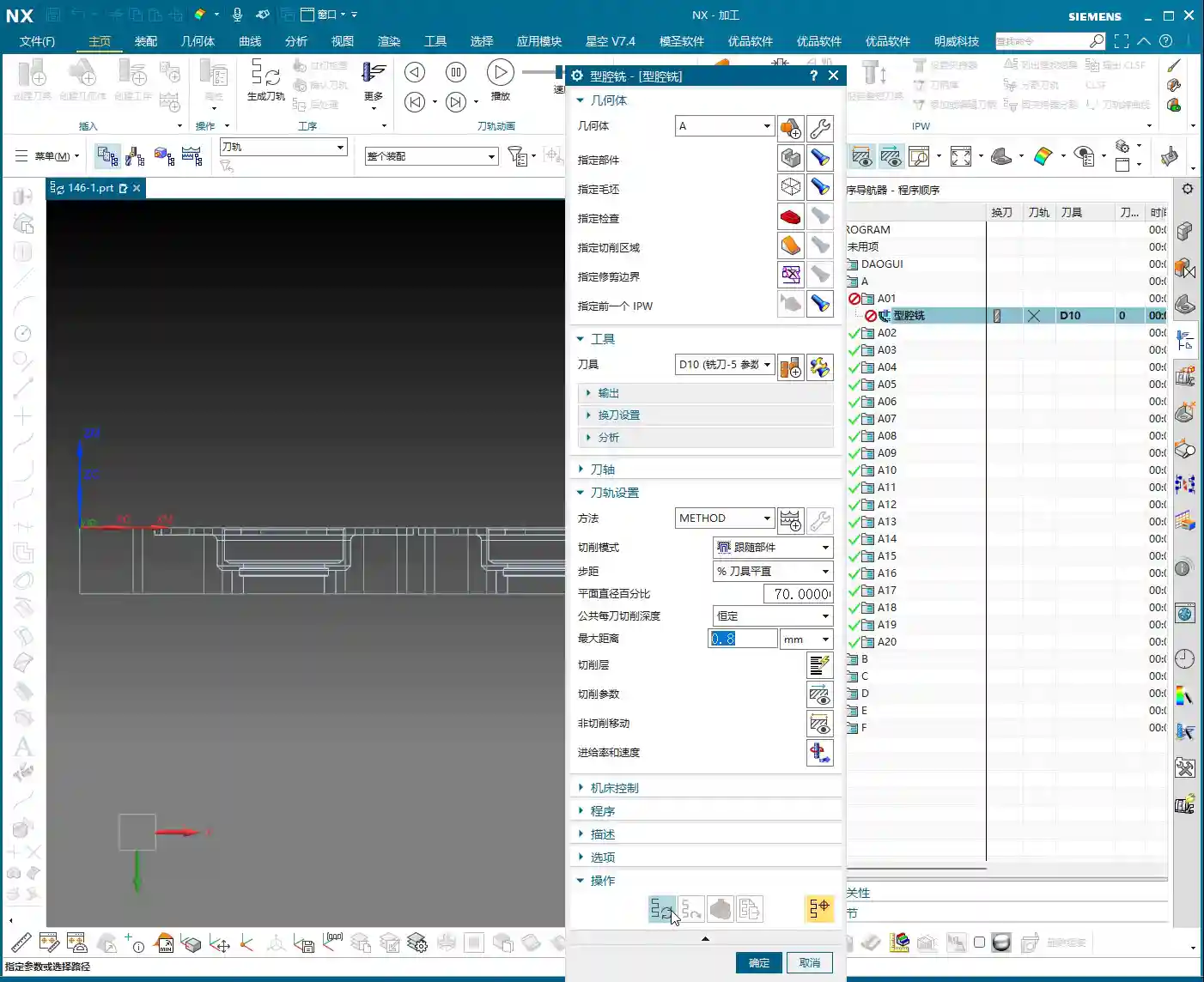
    Step One: Roughing and Finishing Pass for Bottom Face and Side Walls

    Alright, let’s start with an existing program. Once these two programs are run, we’ll definitely need our D10 tool for semi-roughing or the finishing pass. Bottom face and side walls – should we tackle the top or bottom first? Either works, not much difference. However, my preference is to use the D10 tool to finish the bottom face and side walls together. This approach allows us to smoothly machine the large surfaces in one go, laying a good foundation for subsequent finishing passes.

    Simply copy an existing program, open the parameters, and change the machining face to the bottom face we want to finish. Pay attention: if you encounter a hole position, temporarily ignore it; do not machine it. Generate the program, and you’ll see the bottom face and side walls are done in one go.

    Pitfall: Addressing Unconnected Regions (Dead Spots)

    Sometimes, after running the program, you’ll find some residual material in the corners that hasn’t been cleaned up, appearing as if it’s disconnected. These areas are prone to chatter and also affect subsequent accuracy.

    • If you encounter such “disconnected” areas, first check your spatial range settings.
    • Try reducing the size of the “Bounding Box” or adjusting its calculation method.
    • If that still doesn’t work, you need to look at the cutting direction. It might originally be set to “Outside-In”, causing some areas to be missed. In that case, change it to “Inside-Out”. With this change, the tool will clean from the inside outwards, typically clearing those dead spots. Don’t just rely on software simulation; observe the cutting sparks and actual chips – those are the real indicators!

    Step Two: Refined Semi-Roughing and Corner Cleanup

    After the D10 tool has run its course, most surfaces will be finished, but there are definitely still some areas on top that haven’t been machined properly, which are quite noticeable. At this point, we need to perform semi-roughing and corner cleanup. If we just run a semi-roughing pass, these areas will get machined, but I feel some faces aren’t handled particularly well, and the toolpaths might not be ideal.

    Key Technique: Preventing Unnecessary Machining by ‘Patching’ Specific Faces

    When this happens, my approach is to: first ‘patch’ the faces you temporarily don’t want to machine. In Siemens NX, you can use the patching function to ‘cover’ these faces, making the software directly ignore them during toolpath calculation. This way, the tool will only perform semi-roughing on the areas that require corner cleanup, significantly boosting programming efficiency and machining safety.

    • Why do this? Because our semi-roughing operations typically follow “Follow Part”, which traces the part’s outer shape. If run directly, faces you don’t intend to machine will also be included.
    • If you change it to “Follow Periphery”, it might make an inward cut before performing corner cleanup, and the result may not be ideal. Therefore, the best method is to control the machining area by ‘patching’.

    For the specific operation, select the faces that need to be patched, click ‘Patch’, and they will no longer be included in toolpath calculations. This way, our semi-roughing program can focus solely on cleaning up those unmachined corners.

    Program Parameter Adjustments:

    • Tool: Continue using the D10 tool (which is our fourth tool).
    • Depth of Cut (DOC): Control it at the bottom face, for instance, from 0 to -2mm. This ensures sufficient depth for cleanup.
    • Stock Allowance: Leave a small allowance first, for example, 1mm. This will be addressed during the subsequent finishing pass.
    • Spatial Range: Also update to the applicable range for the D10 tool.

    Once the program is generated, those corners and unmachined areas should be mostly cleaned up.

    Step Three: Top Face Finishing Pass

    Semi-roughing and corner cleanup are done; next is the top face finishing pass. This step is relatively straightforward; we can simply copy a previous program and make minor parameter adjustments.

    • Cutting Layers: This time, the cutting layers must be confined to the top face, which is the final machining surface.
    • Stock Allowance: Set all to 0. If you want to play it safe, you can leave a tiny allowance of 0.01mm on the bottom face and side walls to prevent overcutting, but finishing passes usually cut directly to zero.

    Once the program is generated, the top face finishing pass is complete. Now, when you look at it, the entire upper section will be perfectly clean.

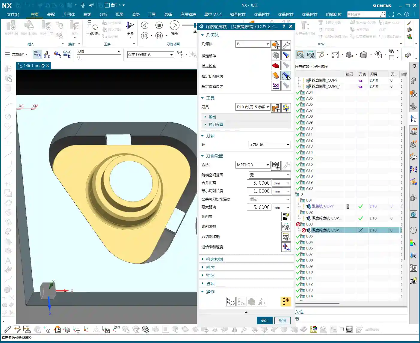
    Step Four: Bottom Wall Finishing Pass (Rest Machining Corners)

    With the top face done, it’s time to tackle the bottom. We’ll use Bottom Wall Milling to clean up the residual material in these areas, especially the corners and radii – what we commonly refer to as ‘rest machining corners’.

    Copy a Bottom Wall Milling program, then:

    • The Sheet Bodies that were ‘patched’ for semi-roughing must now be removed, allowing them to participate in calculations again.
    • Re-select the lower area we intend to machine.
    • Depth of Cut (DOC): For example, set a DOC of 2mm, from 0 to -0.3mm (this is an example; specific values depend on the actual situation, such as wanting the last few passes to be light finishing cuts).
    • Stock Allowance: Leave 0.1mm initially, as there’s still a finishing pass for the side walls later.
    • Toolpath Strategy: For instance, an 85% stepover percentage to ensure efficiency and surface quality.

    Pitfall: Toolpath Deviating? Bounding Box vs. Contour Selection is Critical!

    Here’s a major pitfall! As soon as you generate the program, the toolpath might very well run off to the side, completely outside your intended machining area. Why does this happen? Most likely because your boundary definition is flawed.

    • By default, the software might use a “Bounding Box” to define the machining area, encompassing all selected faces with a rectangular boundary. If your machining area is irregular, this bounding box will be excessively large, causing the toolpath to extend outside the desired region.
    • The correct approach is to change the “Bounding Box” to “Contour”. “Contour” precisely defines the machining range along the boundaries of your selected faces, preventing the toolpath from straying.

    Change this parameter, regenerate the program, and you’ll see — the toolpath now stays obediently within its designated machining area, doesn’t it? That’s the result we’re aiming for!

    Step Five: Side Wall Finishing Pass

    The final step is the side wall finishing pass. The bottom face is mostly done, so next we’ll machine all the side surfaces. Is there a faster way? Absolutely. Copying an existing Side Wall Machining program is the quickest approach.

    After copying, continue using our D10 tool:

    • Toolpath Strategy: Select “Follow Periphery”.
    • Depth of Cut (DOC): Machine from top to bottom in a single pass. This ensures overall surface finish and accuracy for the side walls.
    • Stock Allowance: Set all to 0 for the final finishing pass.

    Pitfall: Stock Control and Cutting Layer Setting Issues

    Problems can easily arise here too. If you generate the program directly, you might find the tool’s cutting start point is suboptimal, or even outside the blank, or the cutting layers are set too high, leading to repeated air cuts.

    • We need to readjust the height control for the cutting layers. For example, you can set the cutting layer start height to half the part’s top, or specify a more precise starting plane.
    • The goal is to ensure the tool begins its cut from a reasonable height, guaranteeing stable engagement with the workpiece without excessive air cutting. For instance, slightly lower the yellow toolpath line to ensure the tool starts cutting from the solid workpiece, not from the air.

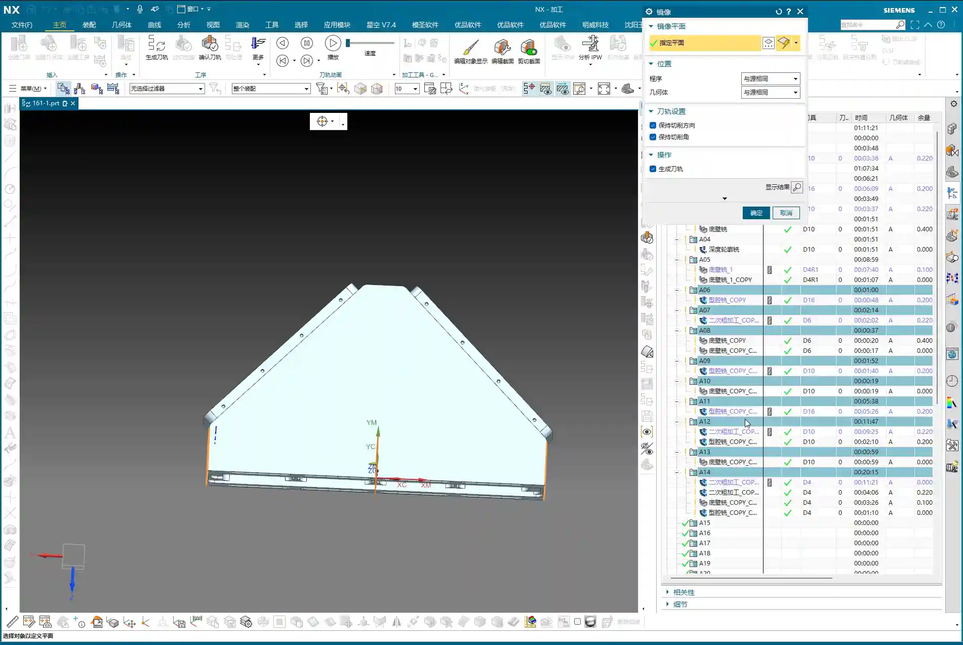
    After these adjustments, the full-process programming for the multi-sided part with an angle head is largely complete. From roughing to finishing, from bottom to top, every step needs close attention to achieve quality results.

    Master Wang’s Mini-Lesson: Toolpath Optimization and Accuracy Control

    Apply What You Learn: Programs Aren’t Set in Stone

    Listen, folks, when it comes to programming, the software is just a tool; your brain is the core. Don’t think that once a program is generated, everything’s perfect – that’s an ideal scenario. On a real machine, there are too many variables. The steps I’ve emphasized aren’t for rote memorization, but for understanding the logic behind them: Why finish corners before flat surfaces? Why ‘patch’ this area? All of this is done to improve efficiency, guarantee accuracy, and extend tool life. Only by applying what you learn can you become a true master craftsman.

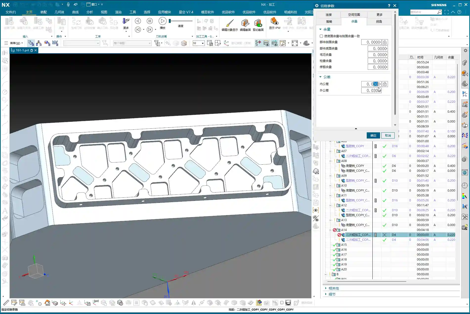
    Tolerance Control: The Secret to ±0.005mm

    You might think a tolerance of ±0.005mm is some mystical feat, but in our trade, it’s routine. Achieving such accuracy requires not only an inherently precise machine but also meticulous process compensation and repeated validation. What I’ve discovered in my 15 years is that relying solely on ideal software toolpaths isn’t enough.

    • Material Properties: Different materials exhibit different deformation during machining. Aluminum is easy to cut, but tough materials like titanium alloys and high-temperature nickel-based alloys require careful handling; they can deform if you’re not meticulous. You must account for dimensional changes after heat treatment and leave appropriate allowances in advance.
    • Fixturing Solutions: A well-designed fixture, ensuring uniform clamping force, is crucial to minimize machining deformation. I’ve ground countless custom tools specifically to accommodate unique fixturing and complex geometries.
    • Stock Allowance Fine-Tuning and Cutting Layer Control: For the final few finishing passes, control the stock allowance to 0.01mm or even less. Tool wear and thermal deformation of the machine can impact these minute accuracies. Sometimes, you need to fine-tune the cutting layer depth or radial stepover to compensate for those infinitesimal errors. Don’t just rely on software simulation; observe the cutting sparks, listen to the cutting sound, and examine chip formation – these are experiential insights not found in books.
    • Machine Accuracy Error Analysis: Even top-tier machines have errors. We must learn to analyze the machine’s geometric and kinematic errors, then compensate through G-code adjustments, post-processor parameters, or even by incorporating minute compensation values directly into the program to keep final dimensions within ±0.005mm. These are all hard-won lessons from practical experience.

    Summary: Pitfall Avoidance Guide

    Finally, here’s a summary of pitfall avoidance guidelines for multi-sided part programming with angle heads, all born from hard-earned lessons:

    • Tool Selection and Management: Distinguish clearly between roughing and finishing, and cleverly utilize the D10 tool. Roughing requires aggressive depths of cut, while finishing demands lighter cuts. Simultaneously, monitor tool wear and replace or regrind tools promptly.
    • Precise Machining Area Definition: Learn to “patch” and “exclude”. For complex parts, don’t attempt a single-pass solution. By patching non-machining areas, you can effectively simplify toolpaths and prevent unnecessary overcutting or air cutting.
    • Toolpath Strategy Selection: The choice between “Bounding Box” and “Contour” is critical. Remember, when the toolpath strays to unintended areas, check the boundary definition; a “Bounding Box” is usually the culprit. Changing it to “Contour” can resolve 90% of such issues.
    • Precise Control of Cutting Parameters: Meticulous control of stock allowance and cutting layer height (stepdown). Especially during finishing passes, it’s better to leave a slightly larger allowance and gradually machine it down than to clear it all at once and cause overcutting. The cutting layer (stepdown) should be determined based on the tool, material, and workpiece rigidity; too deep can lead to tool breakage, too shallow results in low efficiency.
    • Necessity of Real-World Verification: Don’t just rely on simulation; observe cutting sparks and chips. No matter how realistic software simulation is, it cannot replace real feedback from the machine. Spark color, chip formation, and tool sound are all crucial indicators for assessing machining status.
    • Handling Drawing Defects: If you find issues, communicate immediately; do not machine blindly. If the drawing itself has problems (e.g., certain radii are missing), notify design immediately. Never assume and try to fix it yourself, or you’ll be held responsible if something goes wrong.

    Alright, that’s all for today. Remember, machining is both a craft and a technical skill. You need to observe, ask questions, and get hands-on to truly master it!

    👤 About the Author:
    The author is a veteran CNC machining professional with 15 years of industry experience, specializing in UG NX programming. This article is an original work representing personal practical insights.

    ⚠️ Copyright Notice: Unauthorized reproduction or distribution without prior communication is strictly prohibited.

  • Master Wang’s Practical Guide: High-Efficiency NX Programming for a Six-Part T-Slot Plate – Boosting

    📝 Key Takeaways:

    High-Efficiency Programming for a Six-Part T-Slot Plate: A Practical Guide

    Hello everyone, I’m Master Wang. Today, let’s talk about a pra…

    [VIDEO_HERE]

    Hello everyone, I’m Master Wang. Today, let’s talk about a practical job: how to efficiently machine six T-slot parts from a single plate, from start to finish, using NX. This job might look straightforward, but there are plenty of intricacies, especially in process planning and toolpath optimization. A slight oversight can easily lead to problems. Today, I’m going to share all the practical experience I’ve accumulated over the years, leaving nothing out.

    Overall Machining Strategy and Preparation

    Part Analysis and Machining Sequence

    Listen up. When you get a job with multiple parts on one plate, the first thing you need to do is analyze the part features and determine a logical machining sequence. All six parts are identical. Structurally, one side is flat, and the other has a T-slot. My experience tells me: machine the flat back side first, then the front side with the T-slot. This way, once the back side is done, it can serve as a stable datum for fixturing the front side, ensuring stability and minimizing deformation.

    As for geometric creation and blank definition, we’ve covered that in previous lessons, so I won’t rehash it this time. Let’s dive straight into the machining section.

    Blank Definition and Coordinate System Setup

    Before we start, the blank and coordinate system must be correctly positioned. For the blank, we’ll follow our usual practice: place it on Layer 100 for easy management and display. The Machine Coordinate System (MCS) needs to be accurately placed at a datum point on the part. For this job, we’ll use side A as an example, placing the MCS origin at one of the part’s corner points for easy dimensioning. For the other parts, we’ll simply copy the programs.

    Side A Machining (First Side)

    Side A Roughing Strategy

    Side A is relatively simple, primarily involving flat surface roughing and preliminary sidewall machining. Checking the drawing, the part’s outer diameter is approximately 30mm, and the internal dimensions are around 20mm. In this scenario, a 10mm diameter end mill is a suitable choice, balancing cutting efficiency with the ability to machine smaller areas.

    For roughing, we select “Cavity Milling” or “Face Milling” operations, leaving sufficient machining stock. Leave 0.2mm on the bottom surface and 0.2mm on the sidewalls. I usually prefer leaving a tiny negative stock, for instance, -0.1mm, on the bottom. This helps clear the bottom more effectively during finishing, preventing secondary cutting.

    Depth of Cut (DOC) Control: This is also critical. For multi-layered parts like this, depth cuts need to be layered, and you must ensure to avoid the T-slot area (as that’s for Side B machining).

    Side A Finishing Pass and Sidewall Finish Cut

    After roughing, we need to apply a finish cut to the sidewalls. Here, we’re using a “Depth Cutting” operation, still with the 10mm diameter end mill. This operation primarily removes the remaining stock uniformly, bringing the sidewalls to the required surface finish and accuracy specified in the drawing. For finishing, the stock should be set to 0. If the part material is aluminum, feed rates and spindle speeds can be a bit faster, but always observe the cutting sparks and sound—the actual machine condition is paramount, not just software simulation!

    Special reminder: Where there are small angles or chamfers, when finishing the sidewalls, you can appropriately adjust the tool’s Depth of Cut (DOC) to be slightly smaller. This reduces cutting forces, protects the tool, and also prevents part deformation.

    Side A Chamfer Processing

    The small chamfers on Side A will be completed using a “Contour Chamfer” operation. Select a suitable chamfer tool (e.g., a 6mm chamfer mill), set the tool compensation to around 0.2mm, and run it along the edge. Make sure to select an internal chamfer to achieve the desired angle. Don’t miss any edges, and avoid overcutting, especially at corners. Ensure the toolpath is smooth and leaves no burrs.

    Multi-Part Duplication and Toolpath Verification

    Part Array and Program Duplication

    We’re machining six parts on one plate. Once the program for one part on Side A is done, the remaining five are straightforward. Simply use the Array function to duplicate the programs. You’ll first need to measure the center distance between two parts, for example, here we measured 146.82mm. Then, select XY-direction array, set the spacing and quantity, and NX will automatically generate the toolpaths for the other parts. This is much faster than programming each part individually, instantly boosting your efficiency.

    Toolpath Simulation and Detail Check

    After duplicating the programs, you absolutely must perform toolpath simulation and cutting verification. Don’t get lazy! Use NX’s 3D dynamic cutting simulation function to meticulously check every toolpath. Pay close attention to a few key areas:

    • Is there any overcutting or undercutting? Especially at chamfers and fillet radii.
    • Is tool retraction efficient? Minimize unnecessary rapid moves to save significant time.
    • Are entry and exit moves smooth? Avoid impacts to extend tool life.
    • Is the T-slot area mistakenly cut by the Side A program? Confirm it’s clear.

    Through simulation, we can identify potential issues and adjust them in time, solving problems before the machine even starts. That’s the real skill of a seasoned engineer.

    Side B Machining (Second Side – Including T-slot)

    Coordinate System Inversion and Blank Reset

    Once Side A is machined, flip the workpiece over, and we’ll tackle Side B, which includes the T-slot. At this point, the coordinate system must be reset. Invert the MCS to the corresponding datum position on Side B, and again, place it on Layer 100. The blank also needs to be redefined; this time, the blank is the state of the workpiece after Side A machining – in other words, the current blank is the semi-finished product from Side A. If this step is done incorrectly, all subsequent toolpaths will be completely off.

    Side B Roughing Strategy

    For Side B roughing, our main goal is to clear most of the material, especially in the T-slot area. Still use a 10mm diameter end mill, selecting a “Cavity Milling” operation. However, for the T-slot, pay close attention to boundaries and depth. The T-slot’s shape dictates that the tool cannot rough directly to the bottom; it needs to be layered, and sidewall stock for the slot must be considered. We can “enclose” the boundary lines of the T-slot, so the tool will cut within the enclosed area, preventing it from going where it shouldn’t.

    If the T-slot width is relatively large, a 10mm tool might not fit or be inefficient. In that case, consider using a smaller tool or stepped milling. But for this part, I reckon a 10mm tool will handle most areas.

    Side B Finishing Strategy (Fillets)

    Finishing the T-slot requires particular attention. The drawing shows an R1.5 fillet at the bottom of the T-slot, so we must select an R1.5 ball nose end mill or corner radius end mill to finish this fillet. The tool selection must be correct, otherwise, the fillet shape will be wrong. For the operation, you can follow the “Depth Cutting” approach, but ensure the tool can fully enter the T-slot bottom, and the feed must be smooth, without chatter. For the T-slot sidewalls, a finish cut is still necessary to meet size and surface finish requirements. For finishing, the stock should be set to 0.

    After finishing the T-slot sidewalls, finally use a chamfer tool to process all chamfers on Side B, just like Side A. Be meticulous, and avoid rough edges.

    Summary: Troubleshooting Guide

    1. Workpiece Fixturing: It must be secure, especially after flipping the part. The datum surface and locating pins must align perfectly to prevent secondary positioning errors. Achieving ±0.005mm accuracy isn’t just about programming; fixturing is the first hurdle.
    2. Tool Selection: Size, material, and coating must be chosen according to the workpiece material and machining stage. Don’t try to use one tool for everything; large stock for roughing, small stock for finishing – tools need to change accordingly.
    3. Parameter Settings: Feed rates, spindle speeds, Depth of Cut (DOC), Stepover – these parameters are not set in stone. Aluminum and titanium alloys are completely different beasts. Observing cutting sparks, listening to cutting sounds, and feeling the workpiece temperature are “old-school methods” that often work better than textbook formulas for judging if parameters are appropriate.
    4. Optimizing Rapid Moves: Especially with multiple parts on one plate, accumulated rapid move time can be staggering. Carefully check toolpaths; if there’s a shorter path, take it. If a tool can retract less, make it retract less. Squeeze out every bit of efficiency!
    5. T-slot Corner Cleanup: Corner Cleanup inside the T-slot is a challenge. If a small bottom fillet or even a sharp corner is required, consider a specialized T-slot cutter or Electrical Discharge Machining (EDM). Here, with a fillet, an R-tool is the correct approach.
    6. Post-Processing: Don’t assume everything is fine once the program is written. Review the post-processed G-code, especially for 5-axis simultaneous machining or complex operations. You need to be aware of any redundant commands or safety hazards.

    Alright, that’s it for today. Remember, practice makes perfect. Get hands-on, think critically, and you too can become a seasoned engineer like me!

    👤 About the Author:
    The author is a veteran CNC machining professional with 15 years of industry experience, specializing in UG NX programming. This article is an original work representing personal practical insights.

    ⚠️ Copyright Notice: Unauthorized reproduction or distribution without prior communication is strictly prohibited.

  • Siemens NX Guiding Curve Machining Explained: Master Wang Reveals ‘Deformed Mode’ Toolpath Optimizat

    📝 Key Takeaways: Master Wang guides you through practical Siemens NX Guiding Curve Machining, focusing on how to select guiding curves in ‘Deformed Mode.’ Emphasizes that guiding curve arrow directions must be consistent to avoid chaotic toolpaths and scrap. Reveals the secret to controlling toolpath direction via guiding curves, solving complex surface machining challenges, enhancing machining accuracy and efficiency, and preventing thermal deformation.

    Hello everyone, I’m Master Wang. Today, we’re going to continue digging deep into the intricacies of Siemens NX programming to discuss ‘Guiding Curve Machining,’ a feature that often baffles newcomers but is indispensable for experienced machinists. This powerful tool has only been available since Siemens NX 12.0; older versions didn’t have this capability!

    Master Wang’s Lecture: Siemens NX Guiding Curve Machining – An Expert’s Guide to Avoiding Pitfalls

    Listen up. This ‘Guiding Curve Machining’ is quite similar to ‘Surface Milling,’ which we’ve covered before. Both are used for finishing passes. Especially for complex surfaces and small radii, both can generate excellent toolpaths. Sometimes, the programs they produce can even be identical.

    Guiding Curve Machining vs. Surface Milling: Different Approaches, Complementary Strengths

    Don’t underestimate these two; although they seem similar, each has its own quirks. For some jobs, Guiding Curve Machining performs better, generating a smoother toolpath; for others, Surface Milling is the way to go. So, don’t be rigid – if one doesn’t work, switch to the other. That’s practical experience talking! I’m telling you, textbooks won’t teach you these adaptable methods. For example, when machining certain complex freeform surfaces, Guiding Curve Machining often conforms better to the surface, reducing retracts and improving efficiency. Whereas Contour Milling (a type of Surface Milling) might perform better on steep areas.

    Advanced Siemens NX Feature: The Evolution of the Guiding Curve Command

    The true power of this ‘Guiding Curve Machining’ command began to emerge with Siemens NX 12.0; it wasn’t available in earlier versions. Its biggest change is the interface. Now, if you open this command in Siemens NX 1980 or higher, you’ll find its parameter interface is different from before; many options have moved to a sidebar, making it look cleaner. But let me emphasize: What if the interface changed? The core parameters and underlying algorithms remain the same! So, when you’re learning, just grasp the core logic; don’t get bogged down by minor interface changes. Personally, I prefer the higher version interface; it’s more efficient to operate.

    Practical Essentials: Machining Workflow and Key Settings

    Step One: Coordinate System Setup and Workpiece Fixturing

    Standard procedure: before you start working, the Work Coordinate System (WCS) must be correctly oriented. You can place it anywhere, as long as you’ve clearly defined the directions of the X, Y, and Z axes. Remember, for 3-axis machining, the tool axis direction is generally fixed, so establish your WCS first to avoid issues later. It’s the same principle as drafting: a shaky foundation leads to collapse!

    Tool Selection and Machining Area: The Foundation of Finishing Passes

    Next, select your tool. For finishing passes, you typically use a ball end mill. The tool diameter will depend on the fillet radius of your part and the required accuracy. Then, select the area you intend to machine – it could be a single face or multiple faces. Don’t just rely on standard tools from the library; sometimes, for optimal machining efficiency and surface quality, I’ll even grind a custom tool myself. That’s not something you learn from textbooks; it comes purely from experience.

    One more thing to note: options like tool axis control (e.g., ‘Axis and Necessary’) are generally not used in 3-axis machining; those are for 5-axis operations. Leave them alone for now, or you’ll just get yourself confused.

    Mode Type: Understanding the ‘Deformed’ Selection and Its Function

    Here’s the critical part! In the parameter settings for ‘Guiding Curve Machining,’ there’s an option called ‘Mode Type.’ Click the ‘wrench’ icon next to it (which is the ‘Edit’ button), and you’ll see several modes. The most commonly used are ‘Deformed’ and ‘Constant Offset.’ Today, we’ll focus on ‘Deformed’ as an example.

    The ‘Deformed’ mode has its own peculiarities; it requires you to select two guiding curves. These two curves act like a ‘track’ for the tool; the tool will operate between them, forming the machining path. This is somewhat similar to selecting two boundary lines when we learned ‘Planar Profile Milling,’ both serving to define the tool’s range of motion.

    Master Wang’s Secret Techniques: The Mysteries of Guiding Curve Selection and Direction Control

    Selecting Guiding Curves: Where from, where to?

    Selecting guiding curves is straightforward, just like selecting wireframe geometry. First, click the initial curve, then click ‘Add New Geometry’ or simply press the middle mouse button, and then select the second curve. These two curves can be closed or open, as long as they define your desired machining area.

    However, there’s a crucial detail here, and it’s where many newcomers stumble.

    🚨[Pitfall Alert] The Iron Rule of Direction: Guiding Curve Arrows MUST Match!🚨

    After you select two guiding curves, you’ll see a small arrow on each curve. This arrow indicates the curve’s direction. Listen carefully: the arrow directions of these two guiding curves must, and can only, be consistent! They either both point in one direction or both point in the other. Absolutely never one left, one right!

    I’ve seen too many newcomers fail to pay attention to this when selecting curves, resulting in toolpaths that are either chaotic or immediately trigger errors. Sometimes, even the software simulation looks fine, but the moment you put it on the machine, the cutting sparks look wrong, the part precision is way off, or it even experiences tool deflection and becomes scrap! This is no joke; one wrong direction, and your whole day’s work is wasted, with costs pouring out! If you find the arrow directions inconsistent, simply right-click the curve and select ‘Reverse’; it’s quite simple.

    Impact of Different Guiding Curve Selections on Toolpath Direction

    The most powerful aspect of this ‘Deformed’ mode is that your chosen guiding curves directly determine the toolpath direction. This is crucial in practice for controlling machining patterns, preventing thermal deformation, and even for fine error compensation!

    • Case One: Horizontal Guiding Curves, Vertical Machining.

      If your selected two guiding curves are two parallel horizontal lines on the upper part of the workpiece (e.g., the upper and lower edges of a curved surface), then the generated toolpath will machine from top to bottom, or bottom to top, along a direction perpendicular to the guiding curves. This is like using a roller to paint a wall from top to bottom.

    • Case Two: Vertical Guiding Curves, Horizontal Machining.

      Conversely, if your selected two guiding curves are two parallel vertical lines on the sides of the workpiece (e.g., the left and right edges of a elongated feature), then the generated toolpath will machine from left to right, or right to left, along a direction parallel to the guiding curves. This is like using a roller to paint a wall from left to right.

    See that? The choice of guiding curves dictates your tool’s cutting direction! This is especially crucial during finishing passes. For instance, some materials, like titanium alloys or high-temperature nickel-based alloys, are highly sensitive to cutting direction and cutting forces. If the direction is incorrect, it can easily lead to work hardening or thermal deformation. By precisely selecting the guiding curves, you gain control over the tool’s path, bypassing the material’s ‘temperament’ and ensuring part quality and accuracy. What’s more, even when facing minute machine precision errors of around ±0.005mm (approx. 0.0002 inch), I resolve them by adjusting guiding curves and implementing process compensation – now that’s true expertise!

    So, practice frequently, generate toolpaths using different guiding curve combinations, and observe the variations. Gradually, you’ll grasp the subtleties. This is far more useful than simply memorizing theoretical formulas!

    Summary: Pitfall Avoidance Guide

    1. Mode Type Selection: For machining complex surfaces, especially when toolpath direction control is critical, prioritize ‘Deformed’ mode or ‘Constant Offset’ mode.
    2. Two Guiding Curves Required: ‘Deformed’ mode necessitates selecting two guiding curves, which define the tool’s operating range.
    3. The Iron Rule of Arrow Direction: Regardless, the arrow directions of both guiding curves must be consistent! This is crucial for correct toolpaths and avoiding scrapped parts. Otherwise, the toolpath will be chaotic, cutting will be unstable, and accuracy will be completely compromised.
    4. Toolpath Direction Control: By selecting guiding curves in different orientations, you can precisely control the tool’s cutting direction. This is vital when dealing with material characteristics, surface finish, and preventing deformation.
    5. Software Version Differences: While interfaces may differ between older and newer versions, core parameters and functionalities remain constant. Learn to apply knowledge broadly and grasp the underlying logic.

    Alright, that’s all for today. Practice and experiment a lot; you’ve got to get hands-on with these machines; you won’t learn by just watching. Next time, we’ll discuss other practical tips. See you then!

    [EXCERPT]: Master Wang guides you through practical Siemens NX Guiding Curve Machining, focusing on how to select guiding curves in ‘Deformed Mode.’ Emphasizes that guiding curve arrow directions must be consistent to avoid chaotic toolpaths and scrap. Reveals the secret to controlling toolpath direction via guiding curves, solving complex surface machining challenges, enhancing machining accuracy and efficiency, and preventing thermal deformation.

    👤 About the Author:
    The author is a veteran CNC machining professional with 15 years of industry experience, specializing in UG NX programming. This article is an original work representing personal practical insights.

    ⚠️ Copyright Notice: Unauthorized reproduction or distribution without prior communication is strictly prohibited.