Tag: Auxiliary Body Modeling

  • Siemens NX Programming for Backside Finish Milling: Master Wang’s Hands-on Guide to Overcoming Uncle

    📝 Key Takeaways:

    Backside Finish Milling Programming: Practical Tips and Pitfall Avoidance Guide

    Step One: Analyze the Problem, Pinpoint the Root Cause

    Listen up, lads! Today we’re talking about programming for finishing the backside of a component. Don’t be fooled, it might seem like a simple finishing pass, but the higher the demands for flatness and surface finish, the more pitfalls you’ll encounter. Textbooks teach you a bunch of theory, but once you run it on the machine, you might just stare blankly. Today, Master Wang will show you how to get this job done, not just cleanly, but efficiently!

    Initial Attempts and Challenges with Bottom Face Finishing

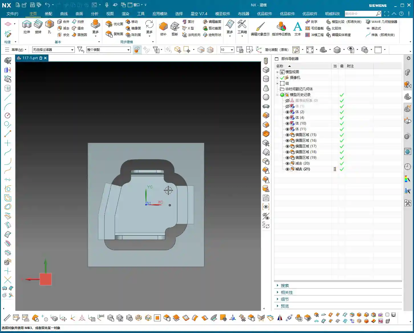
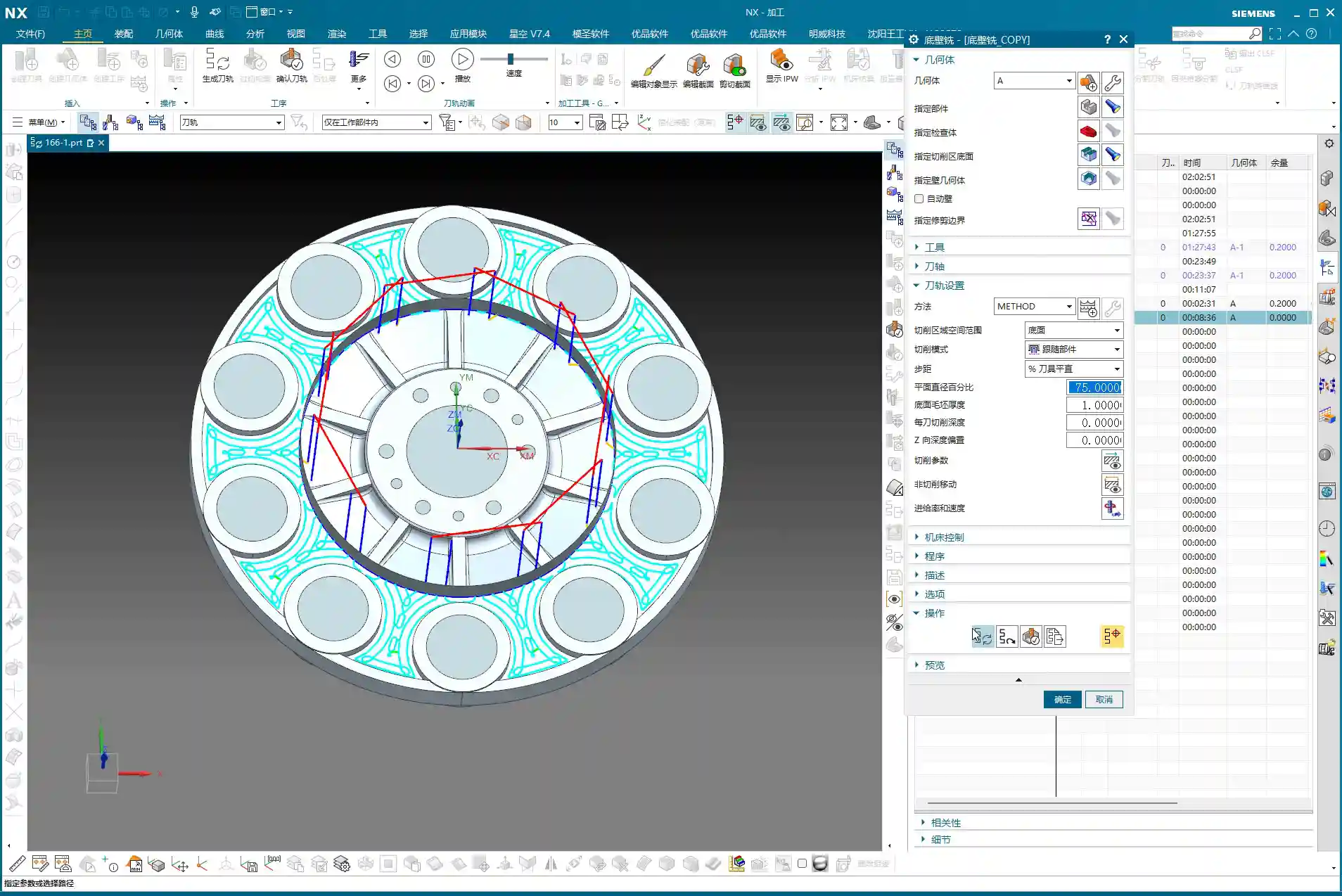
    Let’s start with a standard operation: select the bottom surface to be machined, pick a suitable tool (for example, a D10 flat end mill), set the cutting parameters, and initially leave a small amount of stock. Then generate the toolpath and check the result. And just like that, problems arise!

    Master Wang’s Insight:

    “Look at this toolpath—it doesn’t go all the way to the edge; it turns inward or even breaks off entirely! Isn’t this a classic case of ‘not cutting to the edge’? If that little bit of material on the edge isn’t cleared, how can you expect a good finish? It’s a waste of time!”

    This situation often occurs because Siemens NX, when calculating the toolpath, defaults to not allowing the tool’s center point to exceed your selected machining boundary. This is especially true when your machining boundary is a right angle, and the tool diameter perfectly matches the boundary dimension (for example, a D10 tool hitting a 10mm boundary); it just absolutely refuses to extend even a hair further.

    Step Two: Master Wang’s Secret — Auxiliary Body Construction, Expanding the Toolpath Boundary

    When you encounter this, don’t panic! I’ve been dealing with machines for 15 years, and I’ve seen these little tricks countless times. Textbooks might tell you to switch to a smaller tool or set a negative stock allowance, but those are just temporary fixes. The most reliable, flexible, and efficient method is to add an auxiliary sheet body!

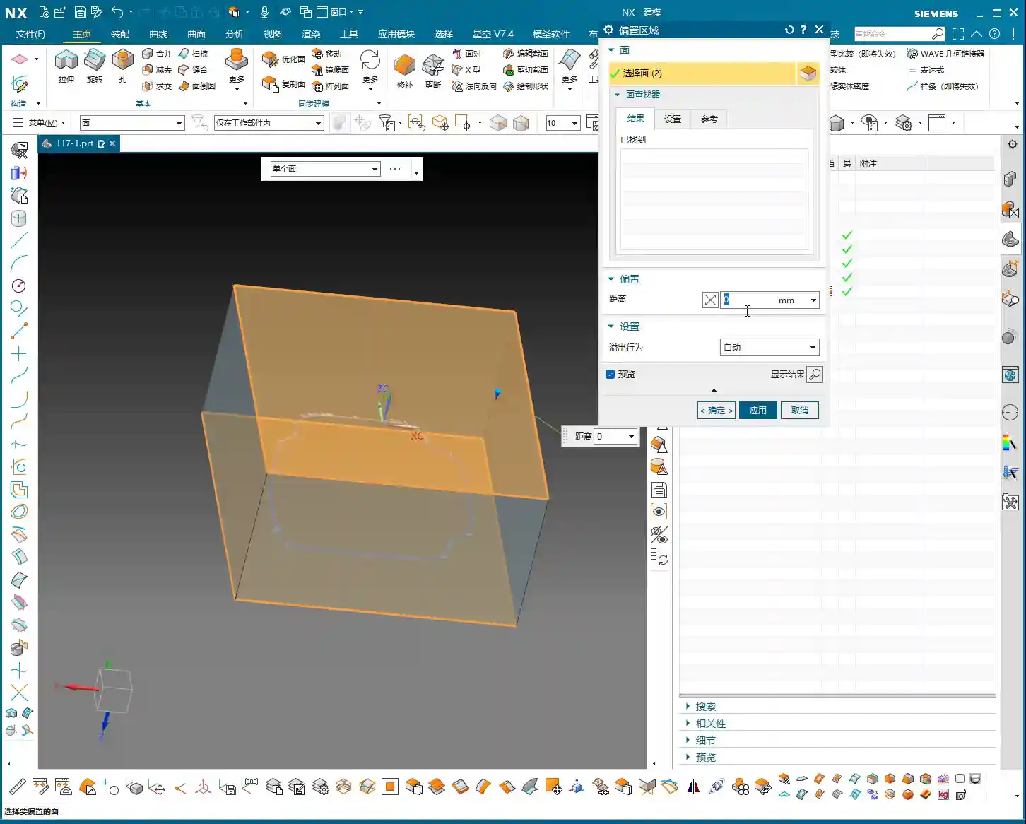
    Precise Measurement and Auxiliary Sheet Body Creation

    1. Measure the Boundary: First, we need to measure the outer dimensions of this bottom surface. For instance, on our part, the radius from the center point to the bottom surface boundary is 145mm. Once we have that number, we can get to work.

    2. Draw Auxiliary Circle: Using the part’s rotational center as the origin, draw a circle with a radius of 145mm.

    3. Extrude to Sheet Body: Extrude this circle into a sheet body. The extrusion height can be arbitrary, as long as it covers your machining area; it’s just a temporary “dummy” body after all.

    4. Set Machining Area: Here’s the key! When programming, the selected machining area is no longer just the original bottom surface. Instead, you include the auxiliary sheet body we just created. This way, when Siemens NX calculates the toolpath, it will assume your boundary has expanded outwards, allowing the tool’s center point to travel further out and completely clear the stock at the corners.

    Master Wang’s Reminder:

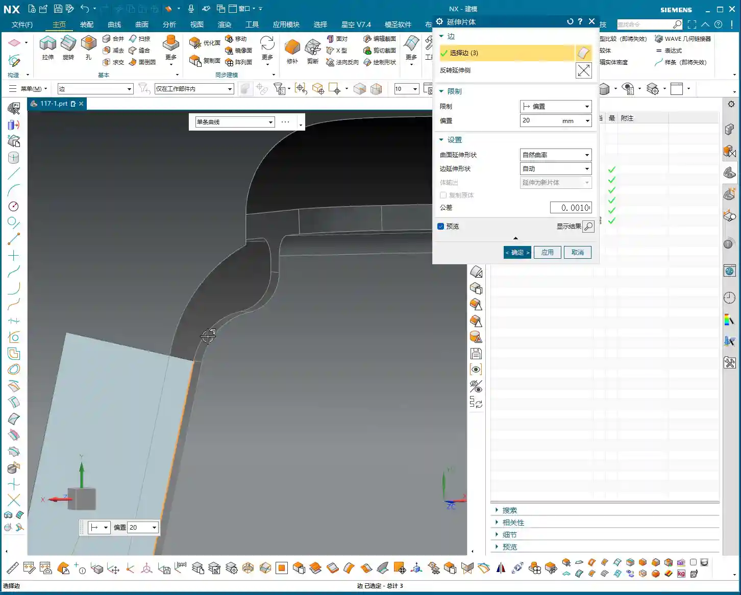
    “This auxiliary sheet body must extend slightly beyond your actual machining boundary. How much? The radius of your tool, plus an additional 0.1~0.2mm stock allowance, is plenty. Don’t add too much, or you might hit something you shouldn’t, and that would be trouble!”

    Tool Diameter Micro-Adjustment – Backup Plan

    If you really don’t want the hassle of drawing an auxiliary sheet body, or if the part geometry is too complex and a sheet body is difficult to create, Master Wang has an emergency workaround. But remember, this method is a temporary fix, not a complete solution, and it’s less effective than using an auxiliary body.

    You can slightly reduce the diameter of the tool being used. For example, if you’re using a D10 flat end mill that theoretically should reach the edge but isn’t, you can change its diameter to D9.99. This allows the tool’s geometric center point to move slightly further out, connecting to that edge. However, use this micro-adjustment cautiously for parts requiring high precision, and it demands a good understanding of your machine’s accuracy.

    Master Wang’s Experience:

    “I typically use this small diameter adjustment when the finishing pass has zero stock allowance but still ‘can’t reach the corner’. While it’s not the ideal method, it can save you in certain emergency situations. But the core principle is still to control the toolpath boundary precisely!”

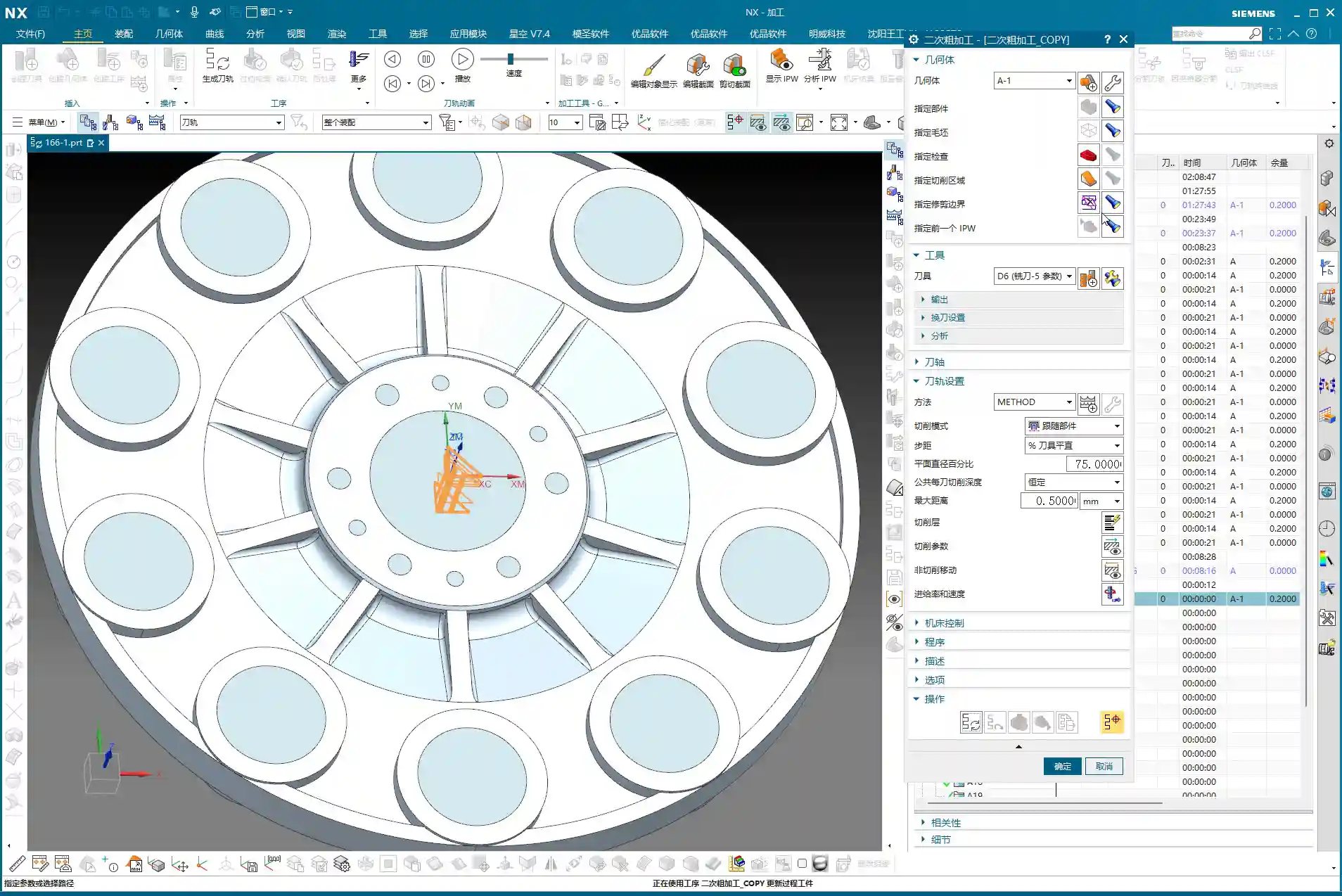
    Step Three: Sidewall Finishing and Toolpath Optimization

    Now that the bottom surface is taken care of, let’s look at the sidewalls. For the same part, the machining requirements for the bottom and sidewalls might differ. Let’s proceed with the sidewalls.

    Sidewall Toolpath Selection and Optimization

    Copy the bottom surface finishing program, then modify the parameters for machining the sidewalls. Choose an appropriate machining method, such as Planar Mill or Contour Profile; either can work.

    For sidewall finishing, a D10 flat end mill is commonly used, making a single pass from top to bottom with a stock allowance of 0. However, at this point, you might find that the toolpath travels too far, with excessive air cuts, leading to inefficient operation.

    Master Wang’s Secret Tip:

    “Look at this toolpath—it looks like it’s trying to finish the entire workbench! This wastes time, wastes tool life, and most importantly, wastes money! In this situation, we need to limit its Space Percentage or Cutting Range. For example, adjust it to 30%, making the toolpath more compact, only traveling back and forth in the truly necessary cutting areas, reducing air cuts, and boosting efficiency. Don’t just look at software simulations; observe the cutting sparks and actual results!

    If the sidewalls have small radii or more complex surfaces, a D10 flat end mill might not be sufficient. In that case, we can copy the program again and switch to a D6 ball end mill specifically for Corner Cleanup of those small radii or surface areas. The machining boundary must also be set correctly to ensure the tool only works within the target area.

    Step Four: Rapid Programming for Symmetrical Parts – Transform and Copy

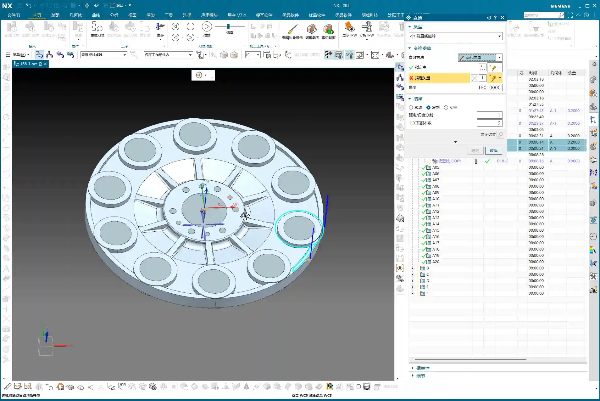
    Many parts are symmetrical, such as features distributed in a circular array. If you program each one individually, you’ll be doing it until the cows come home! Siemens NX’s Transform function is designed precisely for this—it’s a massive time-saver!

    Rotational Copy of Toolpath Programs

    1. Select Programs: First, select the already programmed bottom surface finishing program and sidewall finishing program (or any other programs you need to copy).

    2. Select Transform Type: Go to the “Edit” menu for the program in the “Operation Navigator,” find “Transform,” and select “Rotate.”

    3. Set Rotation Parameters:

      • Rotation Point: Select the part’s geometric center as the rotation center point.
      • Rotation Vector: Select the vector that coincides with the rotation axis, typically the Z-axis.
      • Rotation Angle: If the part has 10 equal divisions, the total angle is 360 degrees, so each division is 360 / 10 = 36 degrees.
      • Number of Copies: This is crucial! Since you already have one original program, you only need to copy 9 additional instances (for a total of 10, subtracting the original). Don’t foolishly copy 10, or you’ll end up with an extra one.

    4. Generate: After confirming the parameters are correct, click OK. Siemens NX will automatically generate the toolpath programs for the other symmetrical areas, saving you a huge amount of repetitive work.

    Master Wang’s Takeaway:

    “This transform function is a powerful tool for boosting efficiency in real-world scenarios! In the same amount of time, others are still programming one by one, while you’ve already generated several sets. This is the true skill of a seasoned veteran, something you won’t learn just by clicking a mouse.”

    Step Five: Program Management and Important Notes

    Once programming is done, it’s not over. Proper program management and attention to small details can save you from many unnecessary headaches.

    Separate Storage for Different Tool Programs

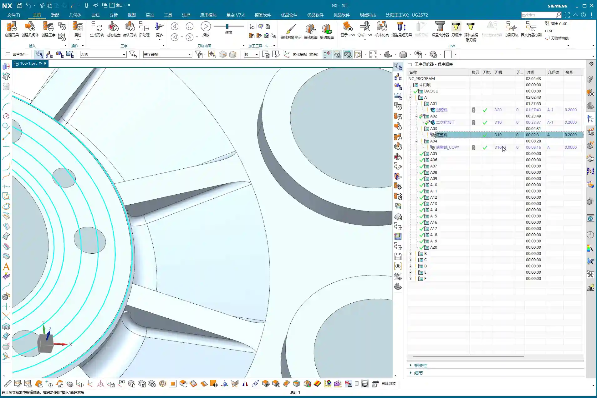
    This is a very important habit! Programs for different tool diameters must never be placed in the same operation group!

    Master Wang’s Emphasis:

    “Listen closely! If you mix D10 toolpaths with D6 toolpaths, Siemens NX will give you an alarm! It assumes that since the tool has changed, the entire program needs to be recalculated. Then you’ll have to separate them one by one—what a hassle, right? So, diligently keep them separate. For example, put D10 programs in A03, D6 programs in A04—clear and concise. This not only facilitates management but also prevents software errors.”

    Always save your work after programming! Develop the habit of saving frequently to avoid losing work due to unexpected situations.

    Summary: Pitfall Avoidance Guide

    What Master Wang has taught you today is practical experience accumulated over 15 years of hard work in the shop. Remember these points, and you’ll avoid detours and achieve excellent results when programming finish milling of bottom surfaces in Siemens NX:

    1. Learn to use Auxiliary Sheet Bodies: When toolpaths fail to cut to the edge, don’t just think about changing tool diameters or negative stock allowances. Constructing an auxiliary sheet body to expand the boundary is the most flexible and thorough solution.

    2. Optimize Sidewall Toolpaths: Reduce unnecessary air cuts by adjusting the Space Percentage or cutting range to make toolpaths more concentrated and efficient. Improving machining efficiency directly reduces cost!

    3. Master Toolpath Transformation: For symmetrical parts, skillfully use rotate, mirror, and other transform functions to significantly boost programming efficiency and achieve more with less effort.

    4. Independent Program Management: Programs for different tools must be stored separately to avoid confusion and software errors, making subsequent management and retrieval easier.

    5. Combine Practice with Theory: Don’t just rely on software simulations. Think critically, observe carefully, and integrate actual machine operation, cutting sparks, and part finish. That’s the real skill!

    👤 About the Author:
    The author is a veteran CNC machining professional with 15 years of industry experience, specializing in UG NX programming. This article is an original work representing personal practical insights.

    ⚠️ Copyright Notice: Unauthorized reproduction or distribution without prior communication is strictly prohibited.

  • Siemens NX Connecting Rib Modeling and Programming: In-depth Analysis of Efficient Clamping and Cutt

    📝 Key Takeaways: Master Wang will guide you step-by-step through NX connecting rib modeling and programming. From part analysis and auxiliary body construction to tool path optimization, this is a fully practical explanation. Learn how to leverage NX techniques to solve complex part clamping and cutting challenges, ensuring both precision and efficiency. Say goodbye to empty textbook theories and tackle real shop floor pain points!

    Listen up, fellas! Master Wang here. Today, we’re skipping the theory and diving straight into solid practical application. This part we’ve got here might look simple, but without a proper plan, you’re guaranteed to run into all sorts of headaches during machining. So today, let’s talk about how to tackle its connecting rib modeling and programming using NX, ensuring your work is both fast and stable.

    Part Geometry Analysis and Machining Challenges

    Quickly Identifying Machining Difficulties

    When you get a part, the first step isn’t to rush into the software. Instead, you need to look closely and analyze it thoroughly. As you’ll see, this part may appear simple, but we first need to understand its ‘characteristics’.

    • Connecting Rib Strategy: For parts like this, creating connecting ribs on the left and right sides is usually straightforward. However, pay attention: there’s an angled face at the front, which isn’t ideal for direct connection. So, we need to adapt flexibly: focus on connecting the left and right sides, while avoiding the angled face.
    • Surface Finish Issues (Flashing Surface): From a top view, some areas of this part show tool marks, which are what we often call ‘machined surfaces’ or ‘surfaces being cut’. But from a bottom view, these marks disappear. This tells us that during programming, we must pay close attention to the cutting direction and tool entry points in these areas to avoid leaving unsightly tool marks on critical surfaces.
    • Angled and Flat Surface Combination: The part’s sides have distinct angled faces, indicating that subsequent machining will definitely involve tilted machining or 5-axis simultaneous machining (if high precision is required). However, most other areas are flat, which simplifies roughing.

    Key Dimensions and Radius (R) Corner Confirmation

    After analyzing the shape, you need to examine the dimensions. Don’t just glance at the general outline; the detailed R corners and clearances will dictate which tool you select and how you program the tool path.

    • Uniform R Corners: We just checked, and all internal R corners are R3. This is excellent, as it means for the finishing pass, a single R3 ball end mill or bull nose end mill can handle most of the details, saving the hassle of frequent tool changes.
    • Connecting Rib Reserved Width: Ultimately, we need to cut off the connecting ribs, which requires reserving sufficient width for tool clearance. For example, measurements show the connecting locations are approximately 12.5mm (approx. 0.49 inch) apart. This gives us ample space to select an appropriate tool for cutting, such as a Ø10mm (approx. 0.39 inch) end mill. Even a Ø8mm (approx. 0.31 inch) tool could work, but you’d need to consider its rigidity and the cutting forces.

    Core Techniques for NX Auxiliary Body Modeling

    An auxiliary body isn’t just a random sketch; it’s crucial for securely clamping your part on the machine while enabling efficient machining. Listen up, this is the real expertise you won’t find in textbooks.

    Function and Preliminary Preparation of Auxiliary Bodies

    Why create an auxiliary body? It’s simple: it provides you with a secure clamping point, preventing the part from vibrating or deforming during machining. Concurrently, it defines your machining area, preventing the tool from cutting unintended regions.

    1. Copy the Part: First, copy the original part to different layers. This is good practice to avoid directly modifying the original model.
    2. Create Stock / Bounding Body: Typically, we start by creating a simple bounding body, such as a rectangular block, as the starting point for subsequent auxiliary body construction. Then, delete the original part, retaining only the bounding body for further operations.
    3. Set WCS (Work Coordinate System): Ensure the coordinate system is set up correctly; this is the foundation for all programming.

    Generating Auxiliary Curves from Tool Path Trajectories

    Master Wang will teach you a trick: directly generate the tool path using the machining module, then extract the tool path boundary to create auxiliary lines. This method offers high efficiency and accurate precision!

    1. Select Machining Operation: We’ll use “Cavity Milling” or a similar roughing strategy, selecting the target face. Note: this isn’t for 5-axis “Contour Profile,” which is used for finishing passes.
    2. Tool Selection: Here, choose a larger tool, such as a Ø25mm (approx. 0.98 inch) end mill. The goal is to quickly generate a rough trajectory around the machining area. Keep only the final cutting layer to retain the bottom trajectory.
    3. Extract Boundary Curve: After generating the tool path, use the “Analysis Tool” and its “Extract Boundary” function to extract the outermost boundary of this tool path. This curve will be the initial shape of your connecting rib.
    4. Curve Extension: The extracted curve should be extended outwards appropriately (e.g., 20mm (approx. 0.79 inch)) so it extends beyond the part’s main body. This ensures that when performing the cut-off operation later, the tool can fully exit the material, preventing remnants.

    Auxiliary Body Thickening and Trimming

    Once you have the boundary, how do you turn it into a solid connecting rib? This requires using “Thicken” and “Boolean operations.”

    1. Create Sheet Body and Thicken:

      • Select the extracted boundary curve and use the “Extend Face” or “Extrude” command to extrude it into a sheet body, which will serve as the base face for the connecting rib. Pay attention to the extrusion direction and height to ensure it fully encompasses the part.
      • Then, perform a “Thicken” operation on this sheet body. For instance, if you’ve left a 1mm (approx. 0.04 inch) allowance, the sheet body’s thickness can be set to 19mm (approx. 0.75 inch), making the total height 20mm (approx. 0.79 inch). Check all faces to ensure a 1mm (approx. 0.04 inch) machining allowance is maintained everywhere.

    2. Boolean Operation Trimming:

      • Perform a “Subtract” Boolean operation between the thickened auxiliary body and the original part. Subtract the original part from the thickened auxiliary body. What remains will be the connecting ribs, conforming to the part’s outer shape and maintaining a clearance from the main part body.
      • Carefully inspect the trimmed auxiliary body to ensure there’s a clear clearance between it and the main part body, and that the connecting rib shape is robust and reliable. If certain areas don’t require extrusion or thickening, retain the original face and handle them flexibly.

    Process Planning and Tool Selection

    Roughing and Finishing Allowance Settings

    Setting allowances is an art, directly impacting tool life, machining efficiency, and final precision.

    • Uniform Allowance: When creating the auxiliary body, we ensured a 1mm (approx. 0.04 inch) allowance was left all around. This allowance is suitable for subsequent roughing and semi-finishing operations. It guarantees sufficient Depth of Cut (DOC) during roughing without being excessive, which could overburden the finishing pass.
    • Staged Machining: Roughing should be fast, aggressive, and accurate, removing the bulk of the material. Semi-finishing aims for a smooth transition, preparing for the finishing pass. The finishing pass is precision work, focused on achieving surface finish and accuracy, requiring a small allowance and sharp tools.

    Connecting Rib Width and Tool Diameter Matching

    The width of the connecting ribs directly dictates which tool you use for the cut-off operation. Selecting the wrong tool can lead to minor issues like tool breakage, or major problems like a scrapped workpiece.

    • Width Calculation: Our connecting ribs have a width of at least 12.5mm (approx. 0.49 inch) at their narrowest point. So, choosing a Ø10mm (approx. 0.39 inch) end mill for the cut-off is perfectly fine; the tool’s rigidity is good, and cutting will be stable. If you want to leave a small finishing allowance, you could even opt for a Ø8mm (approx. 0.31 inch) tool, but you must control the speed and feed rates carefully to avoid overloading the tool.
    • Safety Clearance: For cut-off tool paths, always ensure the tool can fully exit the material. Don’t restrict the cut inside the workpiece – that’s called “confined cutting,” which can easily lead to chatter, chipping, or even tool breakage. Therefore, when modeling, we intentionally extend the auxiliary body’s edges slightly beyond the cut-off path to allow the tool to enter and exit freely.

    Tool Path Optimization Principles

    A well-optimized tool path doubles efficiency and extends tool life.

    • Reduce Air Cuts: NX offers various tool path optimization features, such as “Rest Milling” and “Steep/Non-Steep Area Differentiation.” Strive to keep the tool working within the cutting area, minimizing tool retracts and idle movements.
    • Prioritize Climb Milling: In most cases, opt for climb milling; it provides more stable cutting and a better surface finish. Conventional milling can easily lead to tool slippage and chatter.
    • Appropriate Feed Rates: This relies on experience, don’t just go by software parameters. During actual machining, observe the cutting sparks, listen to the cutting sound, and feel the chip temperature, then gradually adjust to achieve optimal performance.

    Summary: Pitfall Avoidance Guide

    1. Analysis First: Always remember, analyze the part before you rush into anything. Understand its geometric features, R corner sizes, and which faces are critical, only then can you devise the correct machining strategy.
    2. Auxiliary Bodies Aren’t Random Sketches: An auxiliary body is the bridge connecting your design intent to machining reality. It must be sufficiently robust to withstand cutting forces; its shape should be rational to allow easy tool entry and exit; and its dimensions must be precise, matching the machining allowance.
    3. Tool Selection and Path Planning: Select the appropriate tool based on material properties, part R corners, and connecting rib width. Tool path planning must consider efficiency, tool life, and surface finish. Make good use of NX’s optimization features to reduce air cuts.
    4. Allowance is Key: Precisely controlling the allowances for roughing, semi-finishing, and finishing passes is fundamental to ensuring final precision and surface finish. Too little can result in an insufficient surface finish, while too much can cause chatter.
    5. Practical Experience is Paramount: No matter how good the software simulation looks, it doesn’t compare to real cutting with sparks flying on the shop floor. Observe more, think more, summarize more. Only by combining textbook knowledge with practical application can you truly become an expert. Don’t just watch software simulations; look at the cutting sparks!

    👤 About the Author:
    The author is a veteran CNC machining professional with 15 years of industry experience, specializing in UG NX programming. This article is an original work representing personal practical insights.

    ⚠️ Copyright Notice: Unauthorized reproduction or distribution without prior communication is strictly prohibited.