📝 Key Takeaways: Master Wang provides a hands-on guide to practical backside machining in Siemens NX. From Work Coordinate System setup to corner radius end mill corner cleanup and deep pocket side wall finishing, he thoroughly analyzes remnant material handling and toolpath optimization. He also sternly points out the “bloody lesson” of incorrect drilling sequencing, rejecting theoretical discussions and focusing solely on practical shop floor insights and cost efficiency.
Hello everyone, this is Master Wang. Today, let’s skip the fluff and get straight to the facts. The job at hand is backside machining of a part. Many people think backside machining is just flipping the part over and repeating the process – it’s not that simple! There’s a lot more to it, especially subtle details that textbooks might not tell you. Listen closely, today we’re going to clarify the ins and outs of backside machining from start to finish.
Chapter 1: Preparations for Backside Machining – Coordinate Systems and Blanks
Precise Positioning: Work Coordinate System (WCS) Setup
For backside machining, the Work Coordinate System (WCS) is paramount. Get this wrong, and everything that follows is pointless – you might even crash the tool!
- First, the Z-axis needs to be set correctly. Since it’s the backside, the Z-axis usually requires an offset. For example, if the part’s bottom face is 2 mm lower than the blank, then the Z-axis zero point must be set -2 mm lower. This isn’t just an arbitrary number; it requires precise measurement! Otherwise, if the tool stick-out isn’t calculated correctly, you might under-machine the part, or worse, crash into it.
- The Y and X axes should be determined based on the part’s features. I typically align the Y-axis to one edge and the X-axis to another. If a face has already been machined previously, use that face as the reference. Remember, the tool offsetting point must be clearly defined; this is the starting point for all your machining operations.

Blanks, Part Models, and Check Geometries: Siemens NX Fundamentals
These are the most fundamental settings in NX: blank, part model, and check geometry – none can be omitted. But merely knowing this isn’t enough; you also need to understand:
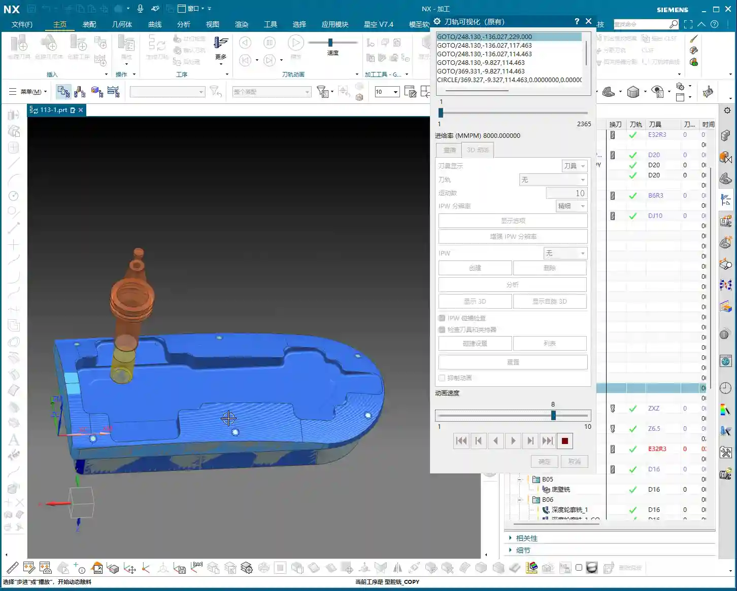
- Which areas were machined in the previous operation? The starting point for backside machining is the endpoint of the previous operation. If there’s remnant material from the previous op, you must account for it in subsequent machining.
- In-Process Workpiece (IPW) analysis is an excellent feature that allows you to visually see where material remains. For instance, areas below that were originally part of the blank are now gone, because they were already machined during the front-side operation. Don’t be complacent; you need to thoroughly plan the entire machining sequence, ensuring smooth transitions between operations.
Chapter 2: Refining Details – Corner Cleanup and Side Wall Machining

Cleaning up Nooks and Crannies: Corner Cleanup with Radius End Mills
Those nooks and crannies on the part are where remnant material loves to hide. For these areas, we need to perform Corner Cleanup using radius end mills. Initially, I might consider an R2 tool, but in practice, an R3 might be more suitable, or as mentioned in the video, a D16R0.8 (16mm diameter, 0.8mm radius). The choice of tool size depends on:
- Stock allowance: The amount of material left during roughing directly impacts the difficulty of finishing pass corner cleanup.
- Tool interference: If the tool is too large, it might not even fit, or it could gouge other surfaces.
Don’t just rely on software simulations. No matter how pretty the simulation looks, if the sparks fly incorrectly when the tool engages on the machine, you’ve got a problem! For corner cleanup with radius end mills, the Depth of Cut (DOC) should be small, and the feed rate stable, otherwise, tool life will be severely compromised.
Remnant Material Management: Patch Opening or N-Sided Surface
After corner cleanup, you might find that some areas still have remnant material due to the limitations of the radius end mill, or there might be irregular holes that need to be addressed. For example, the “hole” in the video:
- If chamfering is required later, it’s advisable to fill it in using the Patch Opening or N-Sided Surface functions. Don’t be lazy; rework later will be more troublesome and will negatively impact chamfer quality.
- I typically place all these auxiliary bodies on Layer 55. This makes management easier, prevents confusion with the main part, and doesn’t interfere with subsequent toolpath calculations.

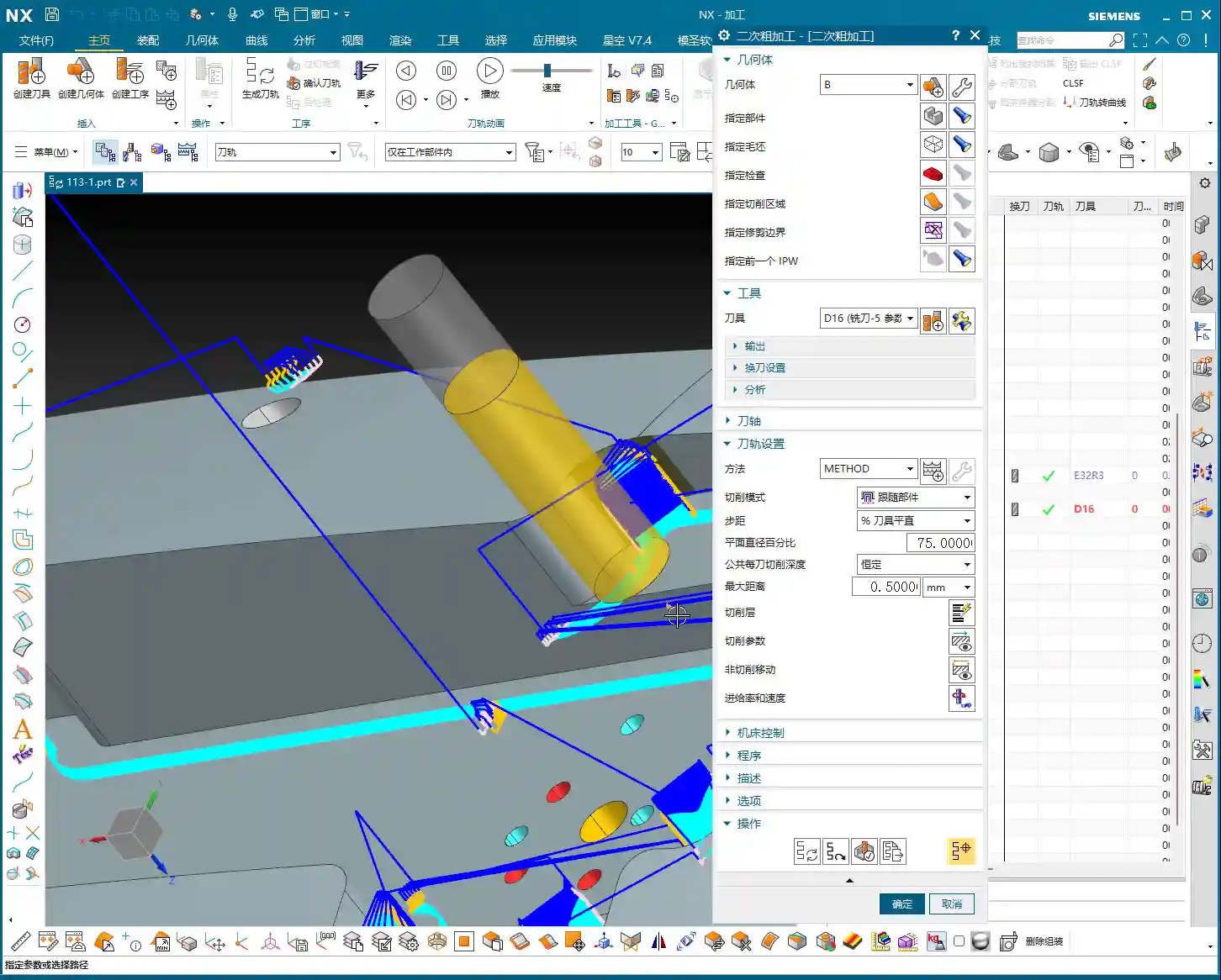
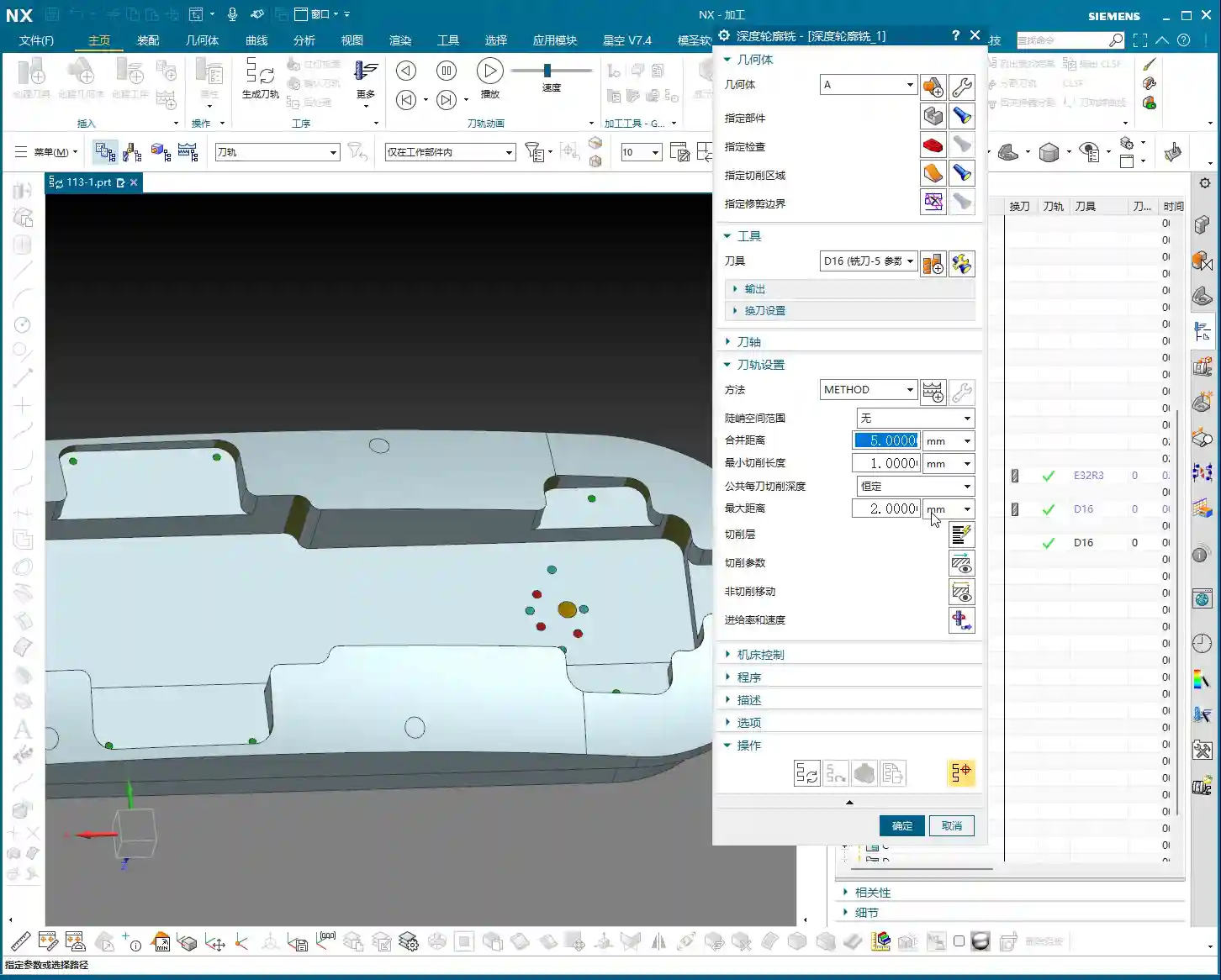
Finishing Pass for Bottom Faces and Side Walls: Flat End Mill Strategy
Finishing the bottom faces and side walls is where your expertise is truly tested. Don’t get the sequence wrong: first finish the bottom faces, then the side walls. This ensures the surface finish of the bottom face isn’t compromised by side wall machining.
- Finishing the bottom face: Use a D16 (16mm diameter) flat end mill with zero stock allowance. The prerequisite is that roughing must be even; otherwise, an uneven finish on the bottom face indicates poor roughing.
- Finishing the side walls (especially deep pockets): If the side walls are quite tall, plunging a single tool straight to the bottom is suicidal! The tool will wear quickly, chatter, or even chip. You must use multi-level machining (layered processing). The Depth of Cut (DOC) for each pass should be determined by the material and tool rigidity. For example, 5 mm (approx. 0.2 inch) per pass, with a side wall stock allowance of 0.5 mm (approx. 0.02 inch), then machined in several passes. This is often referred to as “depth milling” or “helical milling” functionality.
Chapter 3: Major Practical Pitfalls and Optimization – The Fatal Error of Drilling Sequence

Drilling Sequence: A Bloody Lesson Learned
Listen up! This is today’s biggest pitfall! In the video, I just realized that the holes below haven’t been drilled yet. This is a classic machining sequence error!
- These holes should have been drilled right at the beginning, even before finishing the bottom faces and side walls. Why?
- Positioning difficulty: If you try to drill holes after the surfaces are already finished, precise positioning becomes challenging.
- Surface damage: During drilling, the drill bit can leave scratches on the finished surface, or even cause chipping at the edge, directly ruining the results of your previous finishing passes.
- Drilling on curved surfaces: If the hole location is on a curved surface, the difficulty increases significantly, as the drill bit can easily slip, leading to inaccurate hole positions.
Therefore, when manufacturing parts, process planning must come first. Proceed step-by-step; don’t make assumptions. Let me reiterate: Drill the holes first, then finish the surrounding areas! This is an ironclad rule!
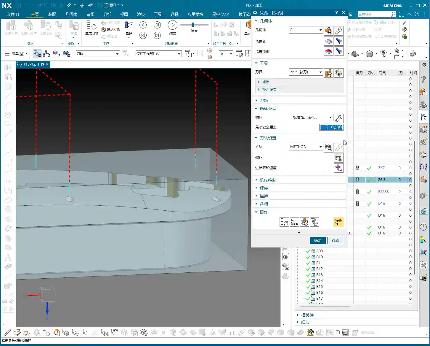
Corrective Measures: Siemens NX Drilling Operations
Since a mistake was made, we need to find a way to correct it. In NX:
- First, use a spot drill to ensure the precise center location of the hole.
- Then, perform the drilling through-hole operation, selecting all hole features that need to be drilled.
- Starting plane: Remember to set it to the highest face of the blank, not the already finished surface. This avoids air cutting and saves machining time.
While corrections can be made, it’s always better to do it right from the start. Remember this lesson!
Summary: Pitfall Avoidance Guide
- WCS Positioning is Fundamental: The Work Coordinate System (WCS) for backside machining must be precise. The Z-axis offset and tool offsetting point are especially critical, directly impacting tool safety and machining accuracy.
- IPW Analysis is Essential: After each operation, always analyze the In-Process Workpiece (IPW) to confirm remnant material. This guides subsequent toolpath optimization, preventing air cuts or missed machining areas.
- Corner Cleanup with Radius End Mills: For complex features and internal corners, flexibly choose radius end mills. Determine the tool diameter and radius based on stock allowance and potential tool interference. Never try to finish all corners with just a flat end mill.
- Auxiliary Geometry Management: For features requiring patching (e.g., holes, faces), utilize NX’s “Patch Opening” and similar functions, and manage them with appropriate layering to ensure they don’t interfere with the main toolpath.
- Layered Finishing for Deep Pocket Side Walls: When machining tall side walls or deep pockets, multi-level machining is essential. Control the Depth of Cut (DOC) per pass to protect the tool and improve surface quality. Adjust side wall stock allowance and depth per pass according to actual conditions.
- Machining Sequence is an Ironclad Rule: CRITICAL POINT! Hole machining MUST be completed BEFORE finishing passes on flat surfaces! Otherwise, it’s highly prone to positioning difficulties, surface scratches, or chipping at the edges, leading to severe quality issues and increased rework costs. This is a bloody lesson learned!
- Don’t Just Rely on Simulation, Observe the Shop Floor: No matter how realistic software simulations appear, they cannot replicate the actual cutting sparks and sounds on the machine. Observe and feel more to truly master the secrets of machining.
👤 About the Author:
The author is a veteran CNC machining professional with 15 years of industry experience, specializing in UG NX programming. This article is an original work representing personal practical insights.
⚠️ Copyright Notice: Unauthorized reproduction or distribution without prior communication is strictly prohibited.