📝 Key Takeaways: Master Wang shares crucial tips for setting ‘Specify Part,’ ‘Check Body,’ and ‘Floor of Cut Area’ parameters in UG NX 1980. From theory to hands-on practice, learn to avoid common beginner mistakes and achieve efficient part machining. Don’t just rely on software simulations; pay attention to the cutting sparks!
Introduction: Starting with Operation Creation
Hello everyone, I’m Master Wang.
Today, we’re going to talk about some parameters within the Floor_Wall (底壁洗) operation and how to create a program. First, let’s take face milling as an example; we’ll mill it once. Then, we’ll process this program.
Alright, first, when we click, for normal operations, we usually right-click and insert an operation.
Of course, you can also click the ‘Create’ button. Down here, one is to create geometry, another is to create a tool, one is to create a tool path, this position is for operation inspection, and this position has ‘Create Operation’. This one is ‘Create Program’. Have you noticed these few? They are all for creation.
So, we can directly click ‘Create Operation’. However, for this step, the program’s location isn’t necessarily fixed to be in A01. For example, if you want it in A10, or say A13, right-click and insert; it will definitely be inside A13. See? When you click ‘Create Operation’, open it, it defaults to what you created last time, so it’s A13. If you want to change it here, it’s a bit troublesome. A is fine, but if you want to create it under F, F-something, it gets a bit cumbersome below. That’s why I generally don’t click that way; I directly click ‘Create Operation’.
I usually insert by right-clicking, selecting ‘Insert’, then ‘Operation’. This inserts it directly.
Operation Template and Basic Parameters
The one at the top, as mentioned, is a template. Select the Floor_Wall (底壁洗) template. This is a Floor_Wall operation. We’ll mainly study the detailed parameters of this Floor_Wall operation to understand what they truly mean.
This position is Program (程序). What does this mean? Simply put, it’s where we create it, for example, within A01. For Tool (刀具), you can select the tool now. Of course, we don’t need to right now; we can select it later. You can select it in a bit.
Geometry (几何体) refers to the A-sequence geometry we created. Remember the A-sequence? We created it as a four-sided square, with the top face as zero. This is a coordinate system, essentially the coordinate system on the machine tool. Inside, there’s only A. We’ll discuss A-1 later.
Uh, for example, at this position, let’s create a geometry. I’ll just create a ‘B’ randomly; I haven’t changed anything. Okay, let’s move it below it.
For B, if you right-click, insert an operation, then B will appear here. You can choose B or A. However, I didn’t make any changes to our B just now, so B won’t work. We’ll still choose A.
Similarly, we can delete this B. Right-click, delete. Good. Right-click, insert operation. If you select the geometry, it defaults to A.
For Method (方法), it doesn’t matter; we won’t discuss methods, so it doesn’t need to be changed. Just select the default here; no matter what it is, the default is fine. The main thing for this page, let’s take a look. The primary thing is that you must select this correctly. Whichever one you want to use, select it. After that, for this, we usually right-click and insert, and it automatically jumps to this; this also doesn’t need changing. This also doesn’t need changing. The only thing to pay attention to is this geometry. Check if the coordinate system you want to use is indeed this one. If it is, then there’s no problem. If it is, you just need to select the sub-program type.
Alright, first, for this page, we actually change very little. Directly click it, then click ‘OK’.
Core Parameter Details: Specify Part, Check Body, Floor of Cut Area
Geometry: Crucial for Selecting the Correct Coordinate System
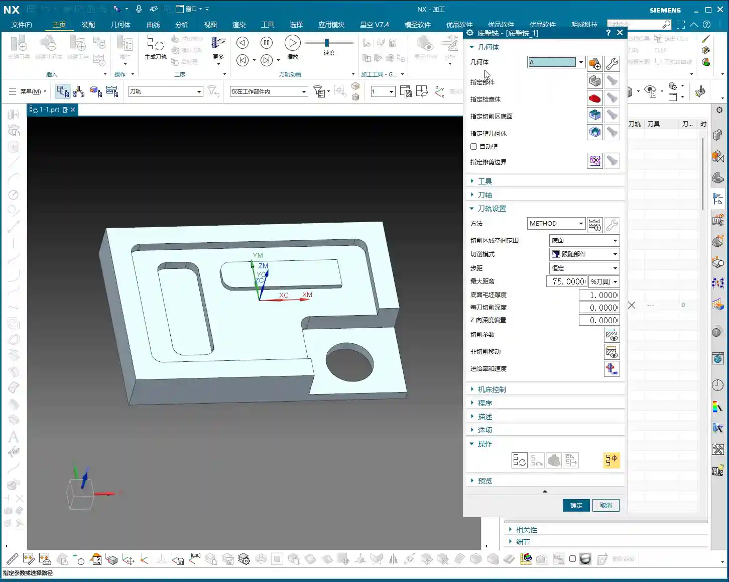
This will bring up a dialog box. Let’s see what it actually means, from start to finish. Let’s talk about it from start to finish.
Geometry (几何体). Alright, there’s ‘Geometry’ here, A. This is the A we are currently using. Of course, you can also change it here. As I just said, this is the same as the A we first encountered. You can also change it, you can change it to B or something. Of course, I deleted that B earlier, so now there’s only A. Usually, this is something we don’t need to change. We already selected it correctly earlier, so no changes are needed. Everyone just needs to understand this. For example, if you selected incorrectly, you can change it again here. This is what geometry means.
Specify Part: Telling the Machine What to Process
Specify Part (指定部件). Alright, this is very important. Look, ‘Select Edit’, ‘Select or Edit Part Geometry’. What does this mean? This is very important.
To put it plainly, in simple terms, ‘Specify Part’ means to designate the part we want to machine. You can select the whole thing, or if you want to machine a specific area, you can just select the entire solid, or just a part of it. For example, ‘Specify Part’, typically, I just click it, then ‘OK’. Selecting the entire part means our component looks like this. You tell the software, ‘My part looks like this.’ Okay, click ‘OK’ directly.
Alright, this is what ‘Specify Part’ means.
Of course, there are many options within ‘Specify Part’. For example, click in here. At this position, there’s solid, sheet. We can also choose ‘no selection filter’. If you don’t want it, for example, if you made a wrong selection earlier, you can just cancel it. Or you can directly select our sheet body, or ‘no selection filter’, just select it directly. It’s all fine. There are no issues.
Specify Part. This is ‘Specify Part’. If you specify it incorrectly, cancel it, then re-specify. Usually, if you specify it this way, there are generally no problems. Filter, you can filter it. Hold down the left mouse button, and since there’s only one solid and no faces, we can just select everything directly. Okay.
Of course, this list might not be open; you need to open it. There’s nothing else worth looking at. We can just click ‘OK’.
This tells the software what our part looks like. Alright, now you understand ‘Specify Part’, right? It means specifying the part we are machining.
Specify Check Body: Avoiding Clamps and Obstacles
Specify Check Body (指定检查体). What does this mean? This means, for example, let me give you an example first.
At this position, if there’s a clamp plate, if there’s a clamp plate at this position, for instance, a clamp plate here. We’re only talking about the usage of this tool here, not whether it’s reasonable or not. Whether it’s reasonable, that’s another matter. So, for example, if there’s a clamp plate here, and another clamp plate here. Then, ‘Specify Check Body’ means that we can set that clamp plate as a Check Body. That’s also possible.
If the clamp plate is set as a Check Body, the tool path will not go over the clamp plate we drew ourselves.
Let’s draw one here. We’ll wait a moment for this; let’s first see if the program can be generated, and then we’ll draw it. Alright, the meaning of this is roughly what I just said. Let me briefly explain ‘Specify Check Body’. Typically, we don’t use this very often; it’s not frequently used.
In general, when I use it, if there’s a clamp plate, I usually select it as part of the Part (部件). If you select it as a Part, it won’t machine that clamp plate. This is also a valid approach.
Specify Floor of Cut Area: Defining the Machining Range
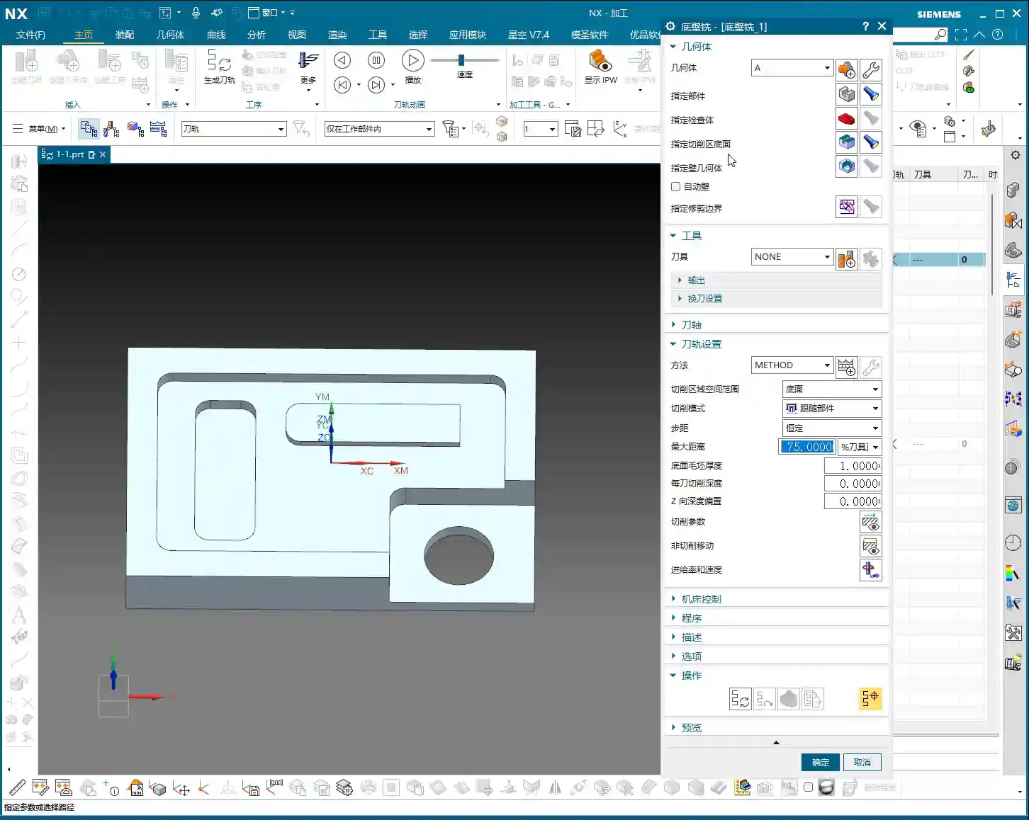
Specify Floor of Cut Area (指定切削区底面). What does this mean? It means whichever position you want to machine, you select that position. For all of these, you click this position. This small display means that if you click the left mouse button, it will show what you previously selected.
Alright, ‘Specify Floor of Cut Area’, click it. For example, if we want to face mill, we select this face. Actually, this Floor_Wall operation has many functions. If you just select one face like this, it can roughly automatically define and combine the entire large face for you. It will automatically combine it here, and it will machine it. If I selected it incorrectly, I’d click ‘X’ to clear it. For example, if I box-selected just now, that definitely won’t work. All areas would be machined. So, if you selected it incorrectly, clear it, and we’ll re-select this face. ‘OK’.
Select ‘Part’, ‘Check Body’, ‘Floor of Cut Area’. Alright, what does ‘Specify B Geometry’ mean? Usually, for face milling, we don’t involve B geometry; it’s not needed for B. So, we’ll skip this.
Next, ‘Automatic B’ is also skipped.
We can talk about ‘Specify Trim Boundary’ later. Let’s generate this program first.
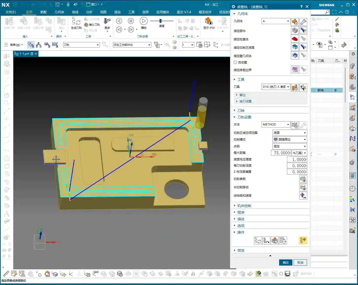
To generate the program, we need to ‘Specify Part’, ‘Specify Floor of Cut Area’, and we need to select a tool. Let’s just pick a tool, for example, a 16mm cutter. Alright, at this point, generate and push it down.
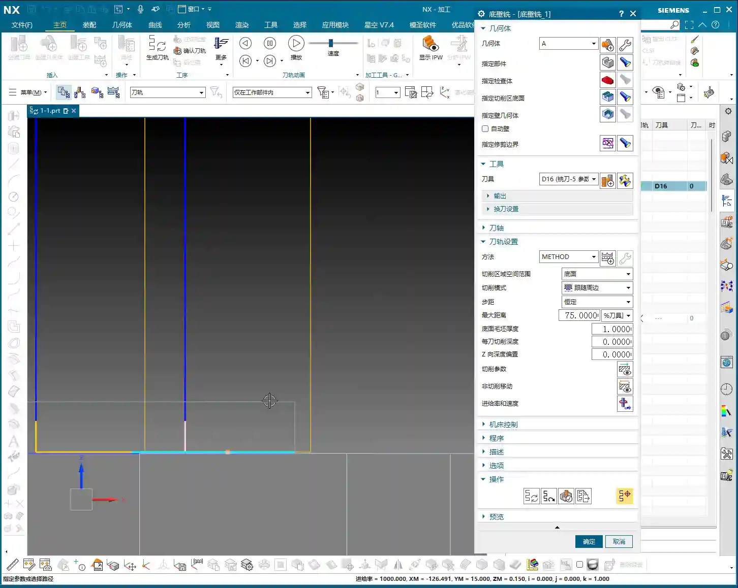
This program is now created. It shows the tool path. It enters the cut from here, then machines, then machines. Alright.
Of course, this is for finishing this bottom face, not for face milling the large top surface. For example, if we didn’t machine anything and needed to face mill this large surface, we’ll talk about that later. Let’s first explain the general meaning of the parameters here.
Check Body in Action: Adding a Clamp
Now let’s draw a clamp. Incremental.
Alright, for example, go to sketch, then click on this face. Alright, draw a rectangle, for example, at this position. Draw one here. Alright, draw another one from this position, draw it a bit smaller. Finish.
Then we’ll extrude it in a bit. Alright, extrude it. For example, I’ll extrude it upwards, let’s give it a distance of, say, 5mm. Alright, ‘OK’.
Summary: Pitfall Avoidance Guide
- Program Settings: When creating an operation, right-click and insert directly in the Program Navigator to avoid incorrect default locations, reducing subsequent adjustments.
- Geometry Confirmation: Always check that ‘Geometry’ points to the correct MCS/WCS (Machine/Work Coordinate System) when creating or modifying an operation. This is the foundation of machining accuracy!
- Specify Part: Clearly tell the software what your workpiece is and which solid or faces to machine. Incorrect selection leads to air cuts or collisions.
- Specify Check Body: This is a collision avoidance tool. When there are clamps, fixtures, or other fixed obstacles, set them as ‘Check Body’. The toolpath will automatically avoid them, preventing machine crashes and saving on repair costs! For less complex scenarios, you can also include the obstacles as part of the ‘Part’ to avoid them.
- Specify Floor of Cut Area: Precisely define the bottom of the machining area. For Face Milling or Floor_Wall Milling, selecting the correct face is crucial, allowing the software to intelligently generate toolpaths and reduce manual trimming.
- Method and Sub-program Type: In most cases, keep these as default. Do not change them unless you fully understand their purpose.
- Prioritize Actual Operation: Don’t just rely on software simulation results. Observe the cutting sparks and listen to the sounds during machine operation, combining experience to judge if the toolpath is reasonable.