Tag: Complex Surfaces

  • Practical Siemens NX: Full-Sequence Programming for Ten Precision Parts on One Plate – Master Wang T

    📝 Key Takeaways:

    Full-Sequence Programming for Ten Parts on One Plate: Finishing Pass and Efficient Duplication

    Hey everyone, Master Wang here. Last time,…

    [VIDEO_HERE]

    Hey everyone, Master Wang here. Last time, we dove into the ins and outs of roughing. Now, let’s go deeper and jump straight into finishing passes, especially for multi-part setups like this. How do you program it to be fast, stable, and still hit those precision targets? Don’t get caught up in fancy software simulations; on the machine, it’s all about real tool wear and machining costs. Listen up, I’m going to lay out all the practical tricks I’ve picked up over the years, right here, right now.

    Finishing Pass for Part Side Walls and Bottom Surfaces

    Once the secondary roughing pass is done, the part’s shape is mostly there. Now, it’s time to think about the finishing pass. The most critical aspects of a finishing pass are toolpath smoothness and precise stock allowance control, which directly impact surface quality and tool life.

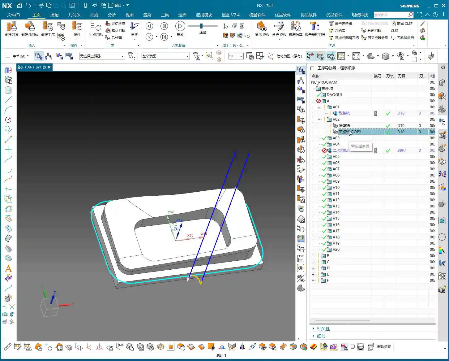
    Floor Finishing: Details Make the Difference

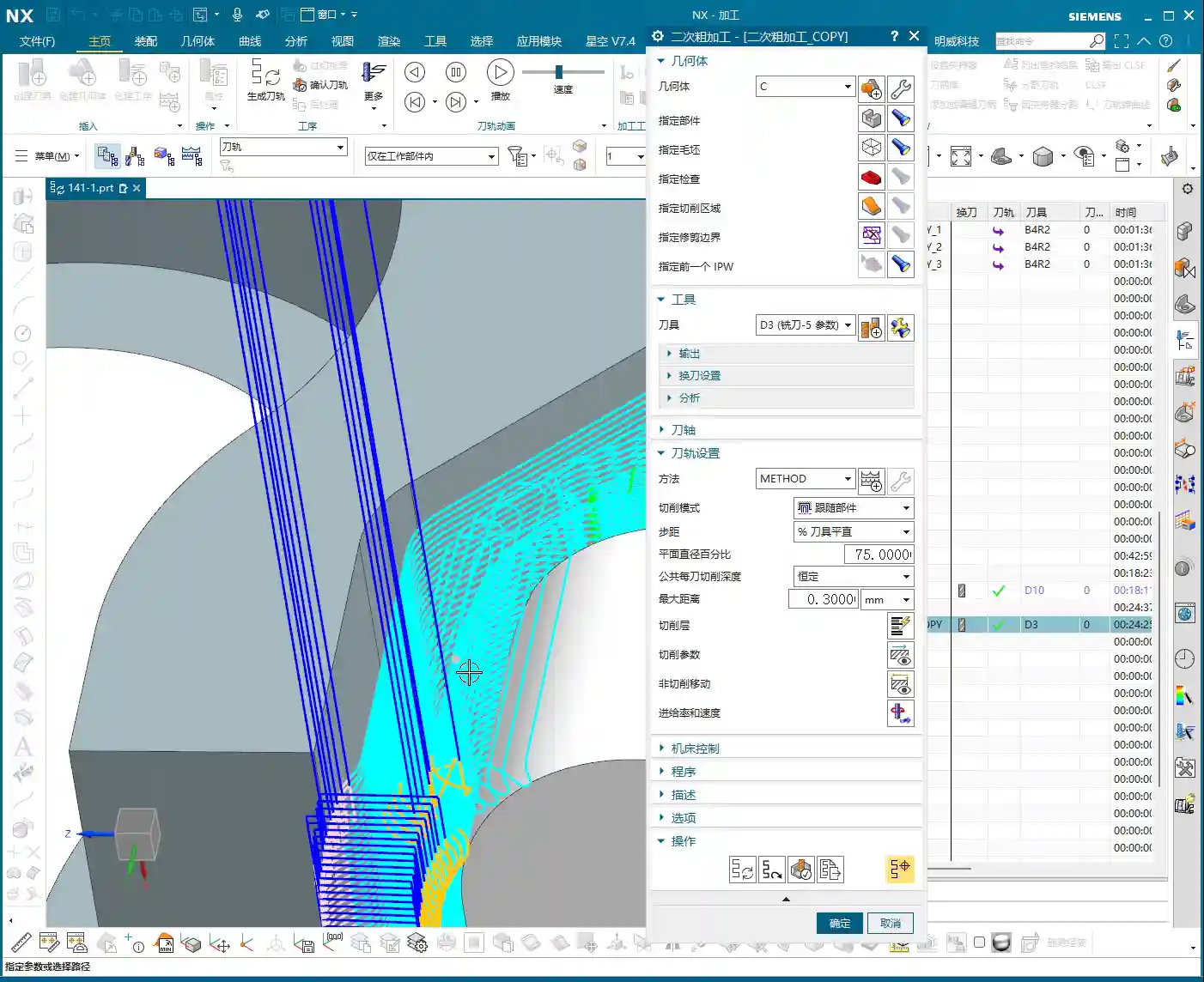
    After secondary roughing is complete, insert an operation. We’ll start with a “floor cleanup.” This operation’s main purpose is to clear the remaining stock at the intersection of the floor and side walls, preparing for the subsequent finish cut. Select the faces to be machined, usually the entire bottom surface area that needs finishing. As for the tool, we’ll use our usual one, for example, Tool #3. While Tool #4 might be more suitable for some jobs, we’ll use #3 here; the principle remains the same.

    Here’s a crucial point: For the toolpath type, select “Follow Periphery,” and remember to choose the direction “Inside Out.” Why? An “Outside In” approach tends to push burrs inward, impacting accuracy, and the tool experiences uneven forces. “Inside Out” results in smoother cutting, easier chip evacuation, and better surface quality. Now, pay attention to the stock allowance control:

    • Side Wall Stock Allowance: 0.2mm (reserved for subsequent side wall finishing pass)
    • Bottom Surface Stock Allowance: 0mm (this time directly finishing the bottom surface)

    And for the corners, give them a slight 1% corner transition. This ensures the tool turns smoothly in the corners, avoiding sudden changes in cutting force that can lead to tool marks or chatter.

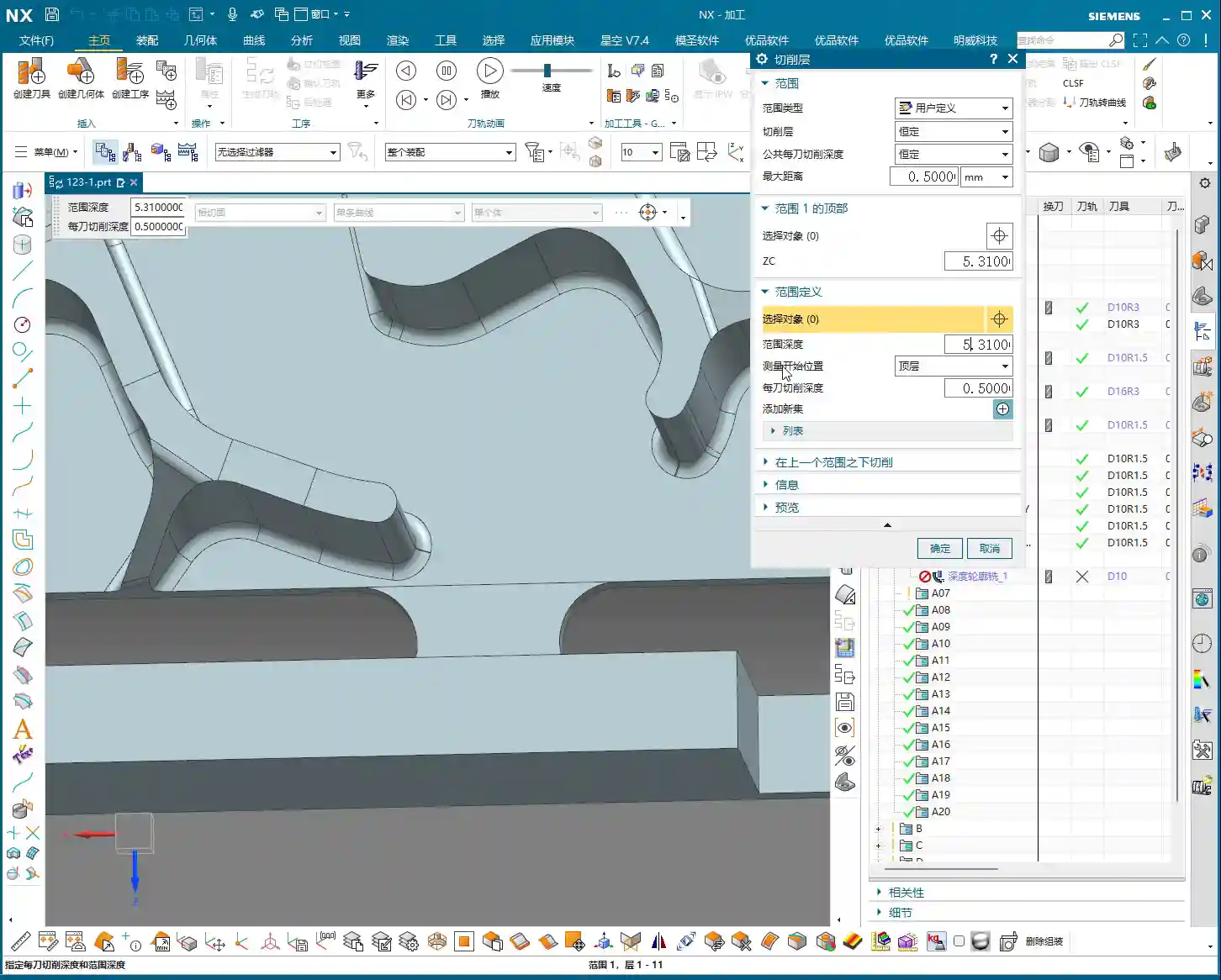
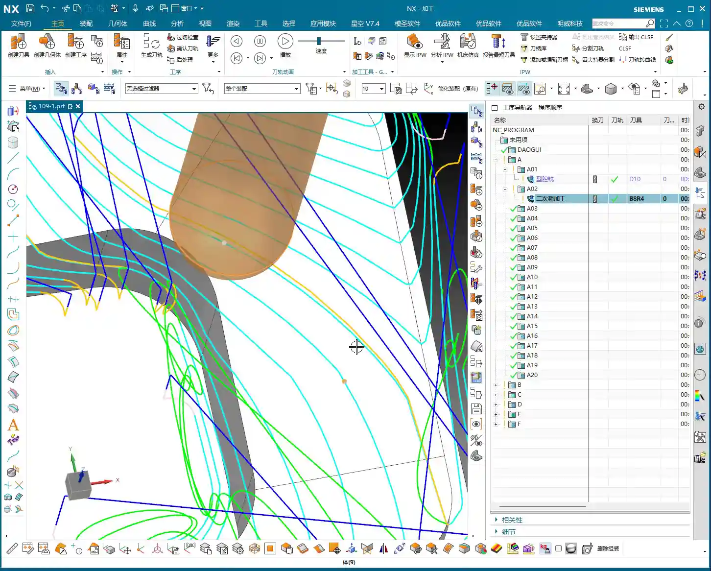
    Side Wall Depth Profile Finishing Pass: Stable Toolpaths are Key

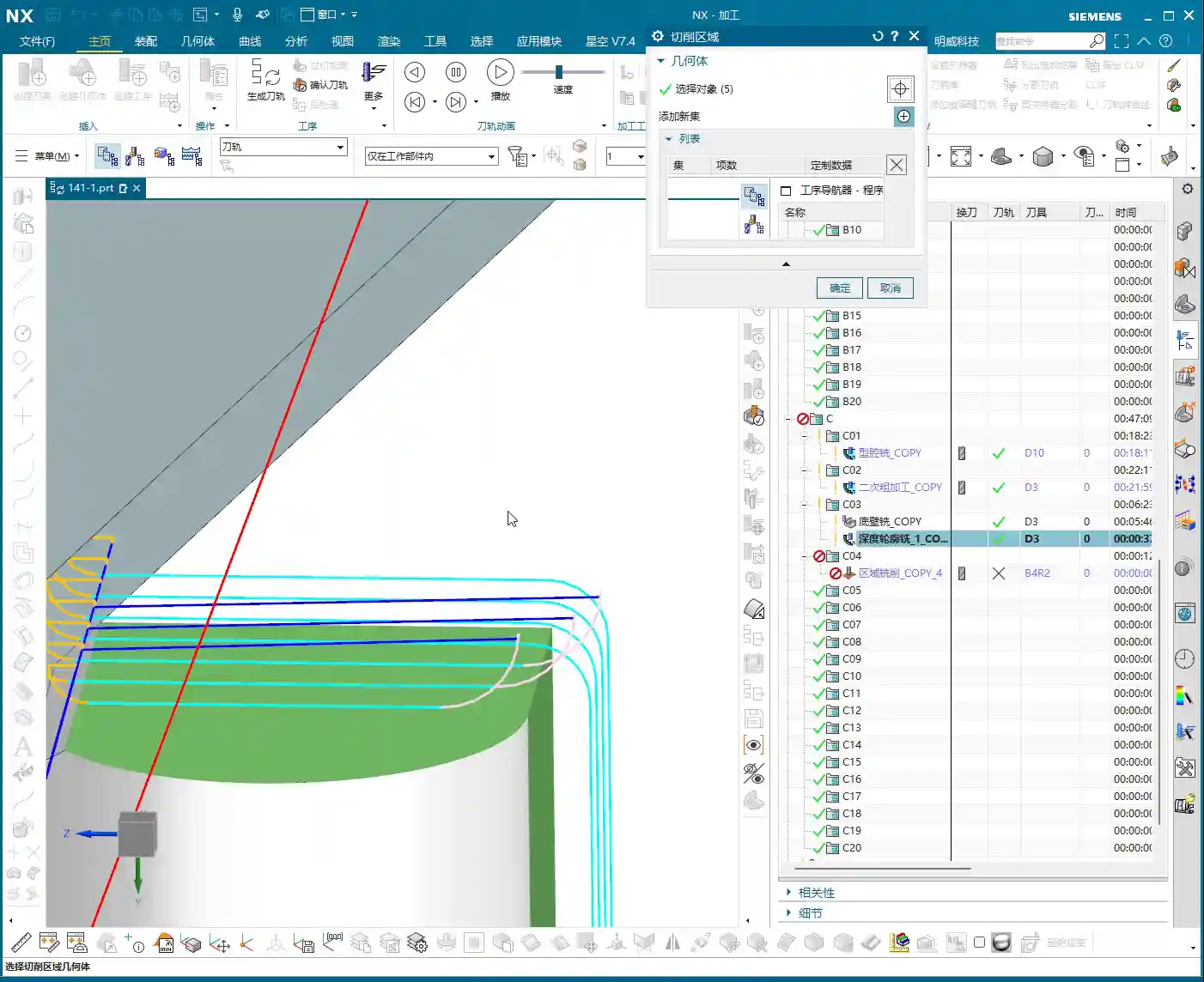
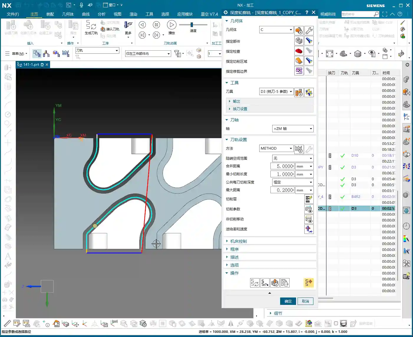
    Once the floor is finished, move on to the side walls. Insert a “Depth Profile” operation and select the side walls to be machined. For beginners, here’s a reliable tip: select both the top and bottom faces. This helps the software better determine the machining range and prevents missed cuts. While mirroring the operation can sometimes work, for safety, especially during the learning phase, selecting all faces is more reliable.

    Continue using Tool #3. Set the depth of cut to 2mm and choose climb milling as the cutting method. This depth of cut needs to be flexibly adjusted based on the material and tool conditions. We’re doing a finishing pass here, so a smaller stepover is fine; the key is surface finish. Generate the program, and if there are no major issues, we’ll stick with this for now. After all, programming isn’t a one-shot deal; constant review and adjustment are standard practice.

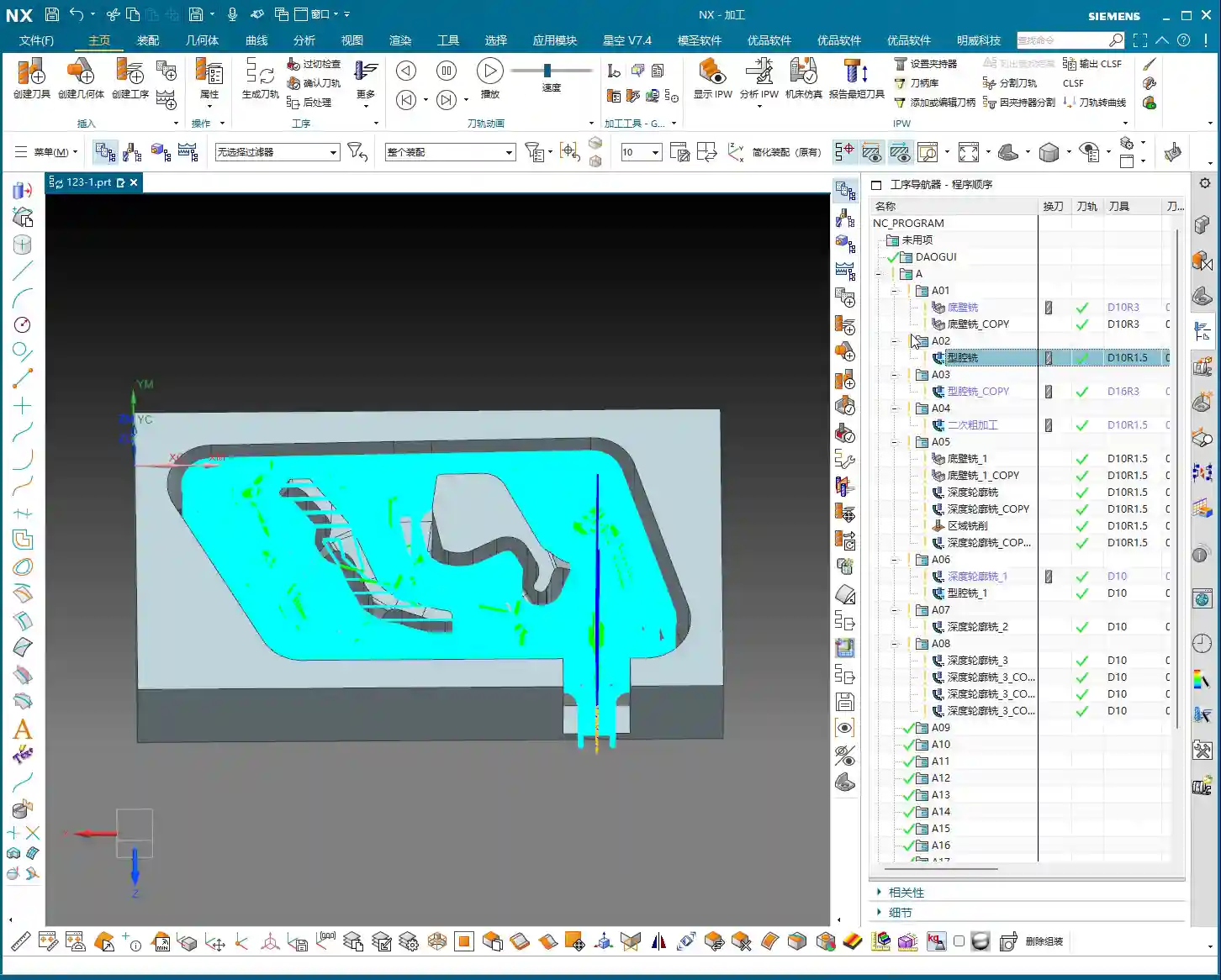
    Complex Surface and Multi-Part Duplication Programming

    Next up is the critical aspect for this batch of parts – the finish contour milling of complex surfaces. Siemens NX’s surface machining capabilities are powerful, but if not used correctly, toolpaths can become erratic and waste precious time.

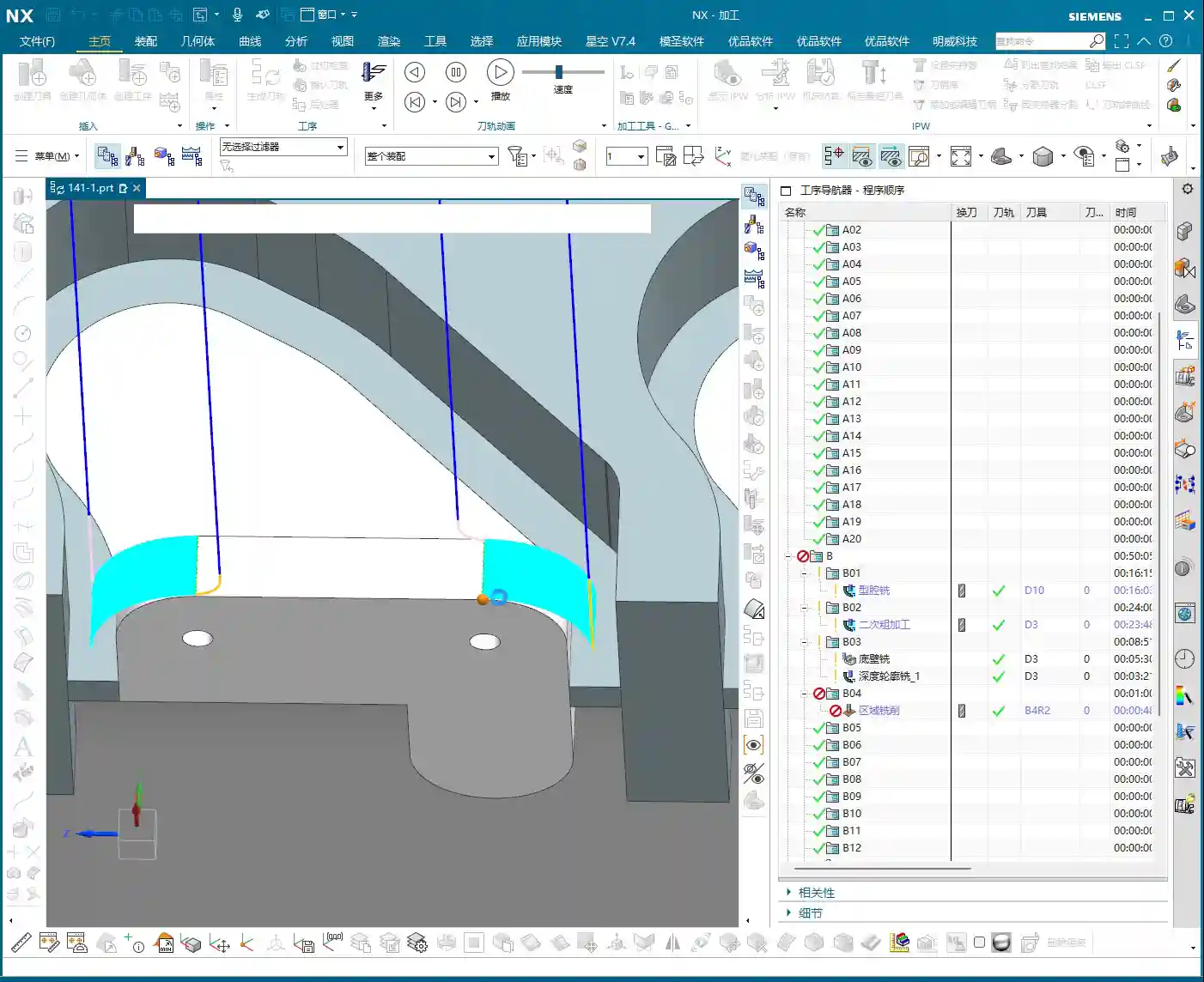
    Surface Finishing Strategy: Flexible Use of a B4 Ball End Mill

    Insert a “Surface Mill” operation and select the surface areas to be machined. For surface machining, we typically use ball end mills, such as a B4 ball end mill. Once the area is selected, generate the toolpath to see the effect. Sometimes you might think certain areas are inaccessible, but with good NX optimization, it can reliably machine them. Since our side wall stock allowance has already been removed, using a B4 ball end mill for direct machining here is generally fine.

    If you find the entry point isn’t ideal, or there’s interference, Siemens NX allows you to adjust it. Just like before, if the entry position wasn’t ideal, we can move it to a more suitable location. For instance, starting the cut directly from a surface edge ensures both safety and cutting stability. These minor adjustments in Siemens NX are all about ensuring safer and more efficient operation on the actual machine.

    Core Siemens NX Programming Skill: Avoiding Unnecessary Retractions

    Listen up, here’s a “pitfall avoidance trick” you won’t find in textbooks! In surface finishing passes, especially with complex surfaces, you might encounter a particularly frustrating issue: after the program is generated, the tool retracts excessively high, sometimes repeatedly, wasting valuable machining time – this is absolutely unacceptable in the workshop. These “ridiculous” retractions often occur because the software, when calculating rapid traverse planes, mistakenly identifies one of your selected “top faces” as an obstruction, assuming something needs to be avoided above it.

    How to solve it? It’s simple: “add a clearance plane!”

    In the toolpath settings, find options related to “clearance plane” or “avoidance.” Manually add a plane. The height of this plane can be set arbitrarily, even slightly higher than your workpiece’s highest point. As long as you add this “virtual” clearance plane, Siemens NX will use it as the new reference plane and will no longer consider your actual workpiece top face as an obstruction. This way, those puzzling, time-wasting “ridiculous retractions” will disappear. Don’t believe me? Try it; this trick works every time and will save you a lot of wasted machining time!

    This stuff comes from experience. Don’t let Siemens NX’s powerful features fool you; sometimes it gets “too smart for its own good.” As masters of the craft, we need to understand its “temperament” and use a few tricks to tame it.

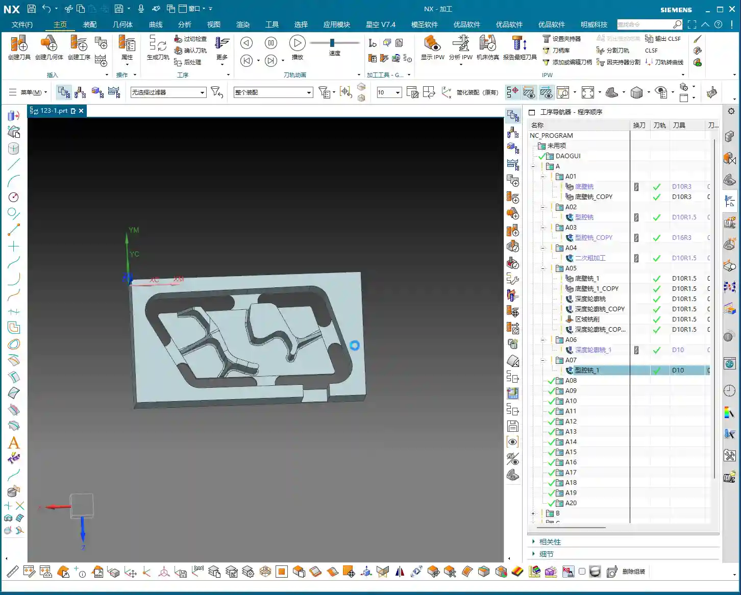
    Efficient Programming for Batch Parts: Translation and Mirroring

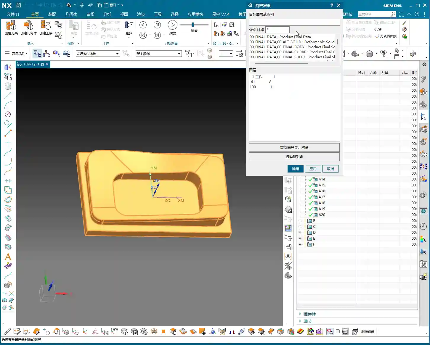
    Since it’s a multi-part setup on one plate, programming each one individually is just plain dumb. Siemens NX’s power lies in its duplication and transformation functions. For parts arranged in a flat layout like ours, “translation” is the most commonly used feature.

    Once the program for the first part is complete, measure the center distance of adjacent parts; for example, we measured 51mm here. Then, directly select the programs that need to be translated (typically all roughing and finishing pass programs) and use the “Transform Object” function. Enter the translation distance 51mm, ensure the direction is correct, click, and the programs for the other parts will be duplicated. We have four similar parts, so translate it three times, and you’re done! This saves a significant amount of repetitive programming time. Simple features like top and bottom faces can be quickly duplicated this way.

    If it’s a front-and-back or symmetrical part, you can use the “Mirror” function. For example, if both sides of a part need machining, program one side, then directly mirror it. With minor adjustments to the trim boundaries and entry points, you can quickly generate the program for the other side.

    Remember this: If it can be copied and pasted, never start from scratch. This is the golden rule for boosting programming efficiency and a key to cost control.

    Detail Optimization and Final Verification

    Back Side Machining and Tolerance Control

    Once all the part programs for one side are complete and verified, it’s time to “flip the part.” After the part is flipped, use the same method to machine the back side. This process is similar to the front side: copy and paste existing programs, then adjust machining faces, toolpath direction, and trim boundaries.

    Here’s a particularly important point: selecting the bottom surface. Sometimes, the software might overlook the finishing pass of the bottom area if you’ve only selected the side walls. While it might seem like a small face and harmless to omit, under high-precision requirements, it’s always best to explicitly select the bottom face to ensure it receives complete machining. If selected, it will definitely be machined; if not, it might leave potential issues. Especially when needing to guarantee accuracy levels like ±0.005mm, any small omission can lead to scrap.

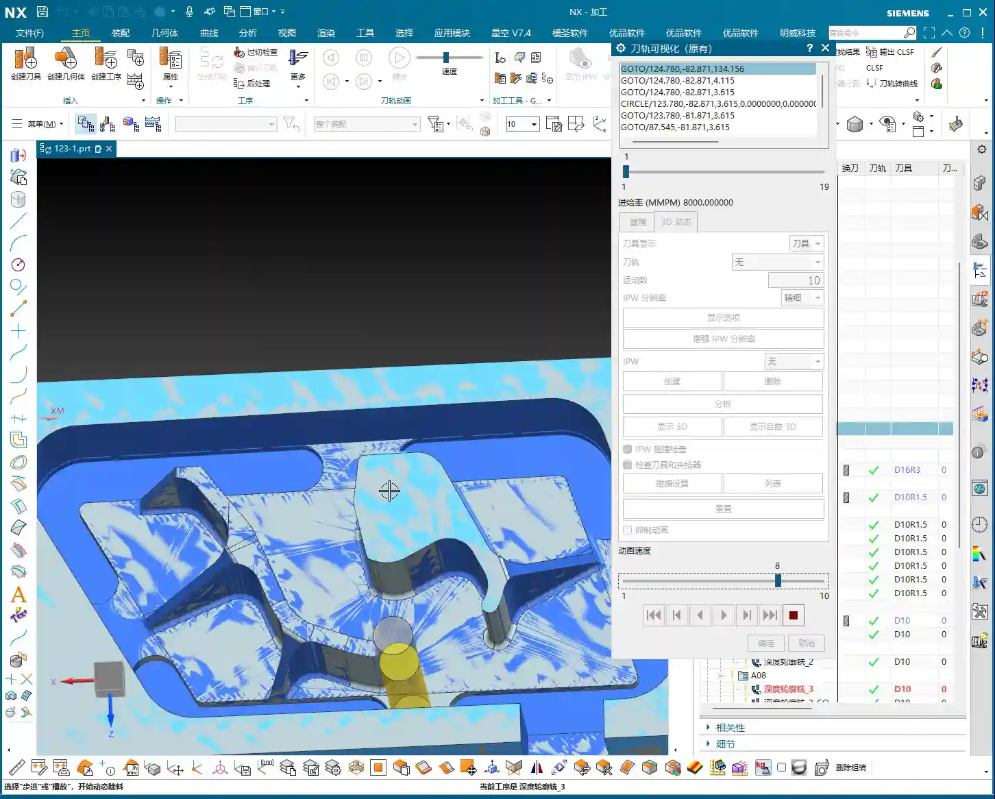
    Final Refinement and Program Verification

    Once all machining programs are complete, it’s crucial to perform comprehensive simulation verification. Don’t just glance through it. You need to meticulously observe the toolpaths, entry points, retraction heights, and most importantly, cutting sparks (though you can’t see sparks in simulation, you need to mentally simulate the machine’s actual running state). Especially critical areas to check are sharp corners prone to heavy cutting, deep cavities, and toolpath transitions.

    If you find any unreasonable aspects in the program, such as unnecessary air cuts or uneven cutting paths, adjust them promptly. Every program optimization saves money and time in actual production. We don’t aim for perfection, but we strive for ultimate practicality and efficiency.

    Summary: Pitfall Avoidance Guide

    1. Machining Direction Selection: When finishing the floor, prioritize the “Inside Out” cutting direction to prevent burr retention and improve surface quality.
    2. Stock Allowance Control: When performing finishing passes on side walls and bottom surfaces, precisely set side wall and bottom surface stock allowances to ensure sufficient space for subsequent operations or to directly machine to the target dimensions.
    3. Secret to Preventing “Unnecessary Retractions”: When Siemens NX generates programs with “ridiculous retractions,” manually add a “virtual clearance plane” above the workpiece. This tricks the software, eliminates unnecessary air cuts, and significantly boosts efficiency.
    4. Batch Programming Techniques: For repetitive parts on a single plate, proficiently utilize Siemens NX’s “Translation” and “Mirror” functions. This can increase programming efficiency severalfold and reduce labor costs.
    5. Select All Critical Faces: When performing depth profile or surface milling, even if some faces seem to have little impact, to ensure accuracy and completeness, cultivate the habit of selecting all faces, especially the bottom face, to avoid omissions.
    6. Simulation Verification: Don’t assume everything is fine just because the program has been generated. Carefully review the simulated toolpaths, simulate the machine’s actual operation, and ensure all details meet requirements before machining to reduce scrap rates.

    👤 About the Author:
    The author is a veteran CNC machining professional with 15 years of industry experience, specializing in UG NX programming. This article is an original work representing personal practical insights.

    ⚠️ Copyright Notice: Unauthorized reproduction or distribution without prior communication is strictly prohibited.

  • Master Wang’s Siemens NX Real-world Case: Master Complex Rib Programming with a Three-Stage Process

    📝 Key Takeaways:

    NX Complex Rib Programming: A Practical Deep Dive into a Three-Stage Process

    Alright, Listen Up, Lads! Master Wang Teaches You Three Tricks to Ace Rib Machining

    Today, we’re not talking theory; we’re getting straight to the practical insights. All that theory you learned in school often leaves you stumped on the shop floor, especially with parts like these ribs that demand both strength and precision. Don’t worry. Today, Master Wang will walk you through this case study, showing you how to program efficient and precise toolpaths using Siemens NX. Remember, machining isn’t just theory; it’s about watching the cutting sparks and listening to the machine!

    Don’t let the simple structure of these ribs fool you; they’re often the backbone of a part, demanding high strength and precision. Especially those small fillets and chamfers at the connections—mishandle them, and you’ll either compromise assembly or create stress concentrations, leading to immediate scrap. That’s why Master Wang has put together a “Three-Stage” programming method that’s guaranteed to be effective and immediately applicable!

    Stage One: Rib Side Wall Roughing / Semi-Finishing – “Aggressive Yet Controlled, Step by Step”

    This is the first, and most crucial, step. The side walls of the rib are often the primary load-bearing surfaces and must be smooth and flat. We need to start with a larger tool to Contour Mill out the basic shape.

    Core Operation: Cleverly Use Surface Milling, Avoid Ball End Mill Pitfalls

    Listen up, here we’re using “Surface Milling”. Why Surface Milling? Because it’s highly adaptable to complex surfaces, creating smoother toolpaths and uniform cutting forces. Some novices see a sloped surface and immediately think of using a ball end mill – a huge mistake! When machining side walls with a ball end mill, the cutting action occurs at the tool’s bottom, leading to low cutting efficiency and prone to Chatter. Especially when the bottom fillet hasn’t been cleared yet, a ball end mill simply can’t reach, failing to “Contour Mill to the bottom surface.”

    • Tool Selection: I typically choose a D12R1.5 (diameter 12mm, 1.5mm corner radius) flat end mill with a radius. Don’t underestimate this corner radius; it significantly boosts tool strength, preventing chipping at the tip, and also simplifies Corner Cleanup in subsequent operations.
    • Infeed and Cutting Parameters:

      • Depth of Cut: If it’s aluminum, you can go with a 0.15mm Stepdown per pass. Don’t get greedy; we’re not chasing speed, we’re laying the groundwork for the Finishing pass.
      • Cutting Pattern: Use “Zigzag” to reduce retracts and improve efficiency.
      • Stock Allowance Control: Leave 0.2mm on the side walls and 0.3mm on the bottom surface. These allowances are for subsequent Finishing passes and Corner Cleanup; don’t machine them all off in one go.
      • Boundary Selection: Precisely select the side wall surfaces to be machined. As for those small fillets, leave them for now; we’ll tackle them in Stage Two.

    Master Wang’s Tip: Software simulations look great, but ultimately, it comes down to the cutting sparks and sound from the machine. If the sound is dull, it indicates excessive cutting force, possibly due to too fast a feed rate or too large a Depth of Cut – you need to adjust it! Excessive sparks suggest tool wear, which also needs attention.

    Stage Two: Cavity Roughing and Local Finishing – “Progressive Refinement, Fine Detailing”

    Stage One covered the main outline of the rib. Now it’s time to tackle the hidden cavities and fillets, which are critical for precision and surface quality.

    Core Operation: Utilize Deep Contour Milling and Cavity Milling Concurrently for Thorough Fillet Cleanup

    This stage consists of two parts: roughing first, then finishing, with targeted strategies.

    • Cavity Roughing (Main Area):

      • Operation Type: We’ll use “Cavity Milling for Roughing”. For material removal in the areas beneath the rib or the main body, cavity milling offers the highest efficiency.
      • Tool Selection: You can still use the previous D12R1.5 tool, or switch to a larger diameter tool depending on the cavity size.
      • Cutting Parameters: Use a 0.5mm Depth of Cut per pass, a side wall allowance of 0.1mm, and set the bottom allowance to 0 this time (as it’s managed internally by the cutting levels), ensuring thorough roughing without overcutting.
      • Depth Control: Start from the top surface of the rib and mill down to the final bottom surface. Remember to leave a 0.1mm machining allowance to prevent milling into the workholding table and to provide room for the Finishing pass.

    • Local Fillet Finishing (Corner Cleanup):

      • Operation Type: The core operation is “Deep Contour Milling”, specifically for Corner Cleanup. It performs multi-level cutting along the part’s contour, making it ideal for internal radii.
      • Tool Selection: Switch to a smaller ball-nose end mill, for instance, a D6R0.5 or D4R0.2. Determine this based on the minimum fillet radius of the rib; the tool diameter must be less than or equal to the minimum fillet diameter.
      • Cutting Parameters: Use a 0.5mm Depth of Cut to ensure stable cutting. Most importantly, precisely control the start and end surfaces, beginning from the bottom surface of the rib, adding the fillet radius as the start height, and milling to the target height.
      • Allowance: Set both side wall and bottom allowances to 0; this pass is about milling it precisely to size, ensuring thorough Corner Cleanup.

    Master Wang’s Tip: When using Deep Contour Milling in complex areas, you might sometimes encounter “Chatter” or “tool skipping” phenomena. If this happens, try reducing the feed rate or adjusting the cutting strategy, for example, from “Conventional” to “Climb Milling.” Don’t be afraid to go slow; stability and precision are paramount.

    Stage Three: Contour Finishing and Final Cut-Off – “A Single Pass for Perfection, The Grand Finale”

    The first two stages have largely taken care of the rib’s forms and internal features. This final stage is about giving the part its “outer finish” and cleanly “liberating” it from the raw stock.

    Core Operation: Smooth Side Walls, Precise Cut-Off, Leave a “Tab”

    This step is crucial for the final surface quality and the integrity of the part; don’t mess it up.

    • Rib Side Wall Finishing Pass (Smooth Side Walls):

      • Operation Type: Continue using “Deep Contour Milling”, as it allows for a precise Finishing pass across the entire side wall, ensuring surface finish.
      • Tool Selection: We’ll use a D10R0.5 ball-nose end mill to ensure the required surface roughness.
      • Cutting Parameters: Use a 1-2mm Depth of Cut, or even go full depth in one pass, to achieve the best surface finish. From the top surface to the bottom, control the final depth by subtracting a 0.7mm allowance.
      • Allowance: Set both side wall and bottom allowances to 0; this is the final Finishing pass, so no more allowance should be left.

    • Final Contour Cut-Off:

      • Operation Type: We’ll still use “Deep Contour Milling”, but this time, it’s to cut the part free.
      • Tool Selection: Continue with the D10R0.5 or a D10 flat end mill, depending on the requirements for the cut-off surface.
      • Cutting Parameters: Use a 0.2mm Depth of Cut, follow the outer contour, and ensure the cutting depth penetrates the part, but be careful not to cut into the Fixturing.
      • Cut-Off Allowance: Here’s the most important part: leave a 0.5mm connection (or even smaller) at the bottom for easy manual break-off or wire EDM later. This is called a “tab”; don’t cut through it completely, or the part will drop, potentially getting dinged or seriously damaged.

    Master Wang’s Tip: For this cut-off step, once the program is ready, be sure to carefully inspect the toolpath on the machine, especially the safety clearance between the tool and the Fixturing. Don’t let the tool hit the Fixturing before it even touches the part – that’s more than a minor issue!

    Summary: Pitfall Avoidance Guide

    • Tool Selection Pitfalls: Don’t always try to use one tool for the entire job. Use larger tools for Roughing, and smaller tools for Finishing passes and Corner Cleanup. Flat end mills, radius end mills, and ball end mills each have their strengths; choose flexibly based on the geometry of the machining area, don’t cut corners.
    • Stock Allowance Control Errors: Leave sufficient allowance for Roughing, and gradually reduce it for Finishing passes. Incorrect allowance can lead to rapid tool wear or failure to meet surface requirements. Especially during cut-off, always leave a “tab” at the bottom to secure the part.
    • Blind Cutting Parameter Selection: Feed rate, spindle speed, Depth of Cut – these parameters aren’t just memorized; they’re determined by a combination of material, tool, machine rigidity, and your desired outcome. Observe the cutting conditions, listen to the sounds, and accumulate experience.
    • Software Simulation Dependence: Even the most realistic Siemens NX simulation is still just a “simulation.” In actual operation, machine vibration, tool wear, and workpiece deformation can all lead to errors. Therefore, for every new program on the machine, run the first part slowly, observing and adjusting as you go – that’s the golden rule.
    • Neglecting Precision Errors: If part precision isn’t met, don’t just blame the machine. Master Wang can “grind out” a ±0.005mm error by adjusting process compensation and toolpath strategies. This requires you to have an intimate understanding of the machine’s geometric errors, thermal deformation, and tool runout.
    • Weak Cost Awareness: When programming, always think about cost and efficiency. Unnecessary air cuts, excessively long toolpaths, and too many tool changes all increase machining time and raise costs. Optimizing toolpaths, minimizing air cuts, and boosting single-tool efficiency are hallmarks of high-level programming.

    Alright, that’s all for today. These are genuine skills Master Wang has honed over fifteen years of hands-on experience – you won’t learn them from textbooks! Digest this well, and next time you encounter ribs, you’ll know exactly how to approach the cut. Remember, in our line of work, experience is the best teacher, and practical application is the only truth!

    👤 About the Author:
    The author is a veteran CNC machining professional with 15 years of industry experience, specializing in UG NX programming. This article is an original work representing personal practical insights.

    ⚠️ Copyright Notice: Unauthorized reproduction or distribution without prior communication is strictly prohibited.

  • Practical High-Efficiency Programming for Complex Sloped Parts in Siemens NX: Master Wang Guides You

    📝 Key Takeaways: Master Wang will guide you step-by-step through programming complex sloped parts in Siemens NX. From part geometry analysis, WORKPIECE setup, and precise tool selection to Roughing, Rest Machining, and Finishing pass toolpath optimization, we’ll reveal practical techniques not found in textbooks. Focus on tackling R-radius rest material challenges on sloped surfaces, meticulously explaining lead-in/lead-out strategies to boost your machining efficiency, cut costs, and move beyond arbitrary programming!

    Initial Part Exploration and Strategy Formulation: Avoiding the “Academic” Approach

    Part Geometry and Material Characteristics

    Alright, folks, listen up! When you get a new part, you can’t just glance at it and start working. First, you need to examine it thoroughly, inside and out, top to bottom, just like I do. This particular part is small, roughly 75x45mm, with a thickness of only 10 to 17mm. It’s a small component, so it requires extra care during machining.

    Let’s start by taking a look using Siemens NX’s Slope Analysis function. This feature is truly invaluable; it can pinpoint those sloped surfaces that might look like simple chamfers to the naked eye but are actually much more complex. See, looking from above, these blue faces are clearly sloped, not just simple chamfers! The bottom, however, is a flat green surface. If you treat these sloped faces as ordinary chamfers, you’re setting yourself up for trouble.

    Also, the R-radius on the part is an obvious R6 fillet. Such small R-radii are a key focus for subsequent Finishing passes; mishandling them will result in rest material.

    As for the material, although it’s not explicitly stated in the video, we need to consider it. If it were a difficult-to-machine material like titanium alloy or high-temperature nickel-based alloy, then cutting parameters, tool coatings, and cooling methods would all need to be re-evaluated. But for today, let’s assume it’s standard aluminum or common steel, ensuring our process flow is sound first.

    Roughing Process Route and Initial Tool Selection

    For a small part like this, with sloped surfaces and R-radii, our approach needs to be clear:
    1. **Roughing:** Prioritize using a flat end mill to remove the bulk of the material. The tool size must match the part’s dimensions; tools that are too large won’t fit into small areas, and small tools will be inefficient.
    2. **Rest Machining:** For the rest material left after Roughing, especially in R-radius and sloped areas, we need to use a ball end mill or a corner radius end mill for Corner Cleanup.
    3. **Finishing Pass:** Use a ball end mill or a suitable finishing end mill again, with a smaller Stepover and finer parameters, to achieve the required surface finish and accuracy.

    For initial tool selection, with an R6 fillet, some might initially think of using a Φ12 tool, but that won’t fit into an R6. We need to choose an appropriate size. A Φ10 flat end mill is fine for Roughing, but pay attention to the potential rest material left on sloped areas. Subsequent Rest Machining and Finishing will require switching to a ball end mill or a tool with a corner radius.

    Siemens NX WORKPIECE Module in Practice: A Weak Foundation Will Bring Down the Whole Structure!

    Blank and Part Definition: The Foundation of Your Program

    In Siemens NX, the WORKPIECE module is the first and most crucial step in programming. It defines the part’s final shape (Part), the initial raw material (Blank), and any fixtures (Check). If these three aren’t set up correctly, even the most beautiful program afterward is useless.

    1. **Part Definition:** Simply select your 3D model.
    2. **Blank Definition:** Here, we’ll choose “3D Model” to define the blank. For easier management, I personally prefer to put the blank on a separate layer, such as Layer 100. This way, when you need to hide or show the blank, you just operate the layer, without affecting the display of the part itself.

    As for the blank’s stock allowance, for this small part, some might initially consider leaving 2mm, but that’s excessive! For small parts, leaving 1mm of stock is sufficient. Too much will only increase Roughing time and could even lead to deformation or tool wear due to excessive cutting forces.

    Coordinate System Setup and Layer Management: Order and Precision

    The coordinate system is our “linchpin” for machining. Set it up wrong, and the entire part is scrapped.

    We need to set the Machine Coordinate System (MCS) at the bottom center of the part and ensure the Z-axis is set to 0. This way, all toolpaths reference this datum, ensuring accuracy.

    Additionally, Siemens NX’s layer management function is often overlooked by novices but mastered by experienced users. For example, place the part model on Layer 10 and the blank on Layer 100. This allows you to easily switch layers to view different models at various stages, improving efficiency and reducing errors.

    Roughing and Rest Machining (Stock Removal) Strategies: Aggressive, Precise, and No Lingering Issues

    Roughing Tool Selection and Feed Parameters

    The goal of Roughing is to quickly remove the majority of the material, leaving a uniform stock allowance for subsequent finishing.

    We’ll start by using a Φ10 flat end mill for Roughing. Cutting parameters must be determined by the material. Spindle speed (S), feed rate (F), along with Depth of Cut (Stepdown) and Stepover, are all critical. The Stepover shouldn’t be too large, or the tool will experience uneven forces, leading to chatter or even chipping.

    After generating the program, remember to thoroughly inspect it using the IPW (In-Process Workpiece) function. Check which areas of the part still have a lot of rest material after Roughing, especially those sloped and R-radius regions. Is the remaining stock uneven? If too much material is left, Rest Machining will require significant effort, and the program might even fail to calculate the toolpath.

    Challenges and Solutions for Sloped Surface Stock Removal

    The sloped surfaces on this part are one of the machining difficulties. If you only use a flat end mill for Roughing, because the tool’s bottom is flat, it’s very difficult for it to cut perfectly along the slope. This results in a large amount of rest material left above the sloped surface, forming “steps.”

    When you finish Roughing with a Φ10 flat end mill, and check the IPW, you’ll see “lumps” all over the sloped surfaces – that’s unacceptable. Especially when you try to use the Rest Machining function to clear this rest material, you might find that the program simply cannot calculate the toolpath! This is because the stock left by the previous operation is too complex and too large, exceeding the current tool’s cutting capability or the algorithm’s limits.

    **Master Wang’s Tip:** When you encounter this situation, don’t force it. Instead, either perform a separate Roughing operation specifically for the sloped surfaces, using a smaller ball end mill or corner radius end mill, or an angle milling cutter, with a smaller Stepover for rough cutting along the slope. Alternatively, during Rest Machining, select a smaller diameter ball end mill and adjust the Stepover and Depth of Cut, allowing it to “climb” these slopes and gradually clean up the rest material.

    Rest Machining Toolpath Optimization and Rest Material Management

    Any rest material not properly handled during Roughing must be remedied by Rest Machining.

    We’ll use a Φ8 ball end mill (or a corner radius end mill, like a Φ12.5R corner radius tool) for Rest Machining. Cutting parameters should be finer than for Roughing.

    * **Depth Per Cut (Stepdown):** Recommended setting is 0.2mm.
    * **Stock:** Leave 0.15mm of stock for the Finishing pass.
    * **Stepover:** This is critical! Compared to the previous Roughing Stepover, the Rest Machining Stepover is typically half or even smaller. For instance, if Roughing used 0.5mm, set Rest Machining to 0.25mm. This ensures effective rest material cleanup, laying a solid foundation for the Finishing pass.

    **Master Wang’s Tip:** Before running the program, always use the simulation function to carefully check the toolpath. Pay close attention to the tool motion in the R-radius and sloped areas, looking for any unmachined sections, overcutting, or collisions. Don’t just rely on the software simulation; visualize the cutting sparks! While you can’t see sparks on the screen, you need to have that concept in mind. In actual machining, cutting sparks are an important indicator of the cutting state.

    Finishing Pass and Toolpath Optimization: The Final Touch for Ultimate Precision

    Finishing Tool Selection and Smoothness Processing

    The Finishing pass is where your skill is truly tested. The goal is to achieve the dimensional accuracy and surface finish required by the part drawing.

    For this part, especially the sloped surfaces and R-radii, we still need to use a ball end mill. For example, a Φ8 ball end mill can effectively balance accuracy and efficiency.

    * **Stepover:** Must be set small enough, such as 0.15mm to 0.2mm, to ensure surface finish. A larger Stepover will result in more noticeable “tool marks.”
    * **Smoothness:** Increasing this parameter will make the toolpath smoother, reduce tool impact, and improve surface quality. You can try adjusting the smoothness to 400% and observe the effect.

    Lead-in/Lead-out Strategy Adjustment: Details Determine Success

    Lead-in and lead-out, seemingly minor details, have a huge impact. Unreasonable lead-in/lead-out can leave tool marks at best, or cause tool wear and even chipping at worst.

    As you can see, the initial toolpath might have an abrupt lead-in, moving straight in like the yellow line. This direct entry/exit method can easily leave “tool marks” on the part surface.

    **Master Wang’s Tip:** We need to change the lead-in method to “Arc Lead-in”. By smoothly cutting into the material with an arc, you can significantly reduce tool marks and improve surface quality. The same applies to lead-out; try to use an arc or a diagonal line for lead-out.

    Remember, every time you modify the toolpath, you must regenerate it and then carefully check with simulation.

    Summary: Pitfall Avoidance Guide

    1. **Don’t blindly trust your eyes:** For complex geometric features, especially sloped surfaces that look like chamfers, be sure to use professional tools like Slope Analysis for confirmation to avoid misjudgment and subsequent machining problems.
    2. **WORKPIECE setup is foundational:** Ensure that the Part, Blank, and Check definitions are accurate, and that the blank’s stock allowance is reasonably set according to the part’s size and material characteristics. For small parts, don’t leave too much stock.
    3. **Coordinate system and layer management:** Correctly set the Work Coordinate System (MCS) and effectively use layer functions to manage models, improving work efficiency and accuracy.
    4. **Roughing must consider subsequent operations:** During Roughing, aim to leave uniform stock, especially in sloped and R-radius areas. If a flat end mill cannot effectively clear the material, consider using a smaller diameter ball end mill or angle milling cutter for localized Roughing to avoid the embarrassment of the “program failing to calculate” during Rest Machining.
    5. **Rest Machining is the cleanup crew:** Select appropriate ball end mills or corner radius end mills, and set a reasonable Stepover (typically half or even smaller than Roughing’s) to ensure all rest material is cleaned, establishing a good foundation for Finishing.
    6. **Finishing demands attention to detail:** The Finishing pass’s Stepover must be small enough, and lead-in/lead-out methods should be smooth (Arc Lead-in recommended) to achieve the best surface quality and accuracy.
    7. **Simulation check is paramount:** After every program generation or modification, toolpath simulation must be performed to check for overcutting, undercutting, collisions, and other issues. This is far less costly than rework afterward!
    8. **Balance cost and efficiency:** All process choices and parameter settings must ultimately return to cost and efficiency. Appropriate tools and reasonable toolpaths must ensure quality while also considering machining time.

    Alright, that’s all for today. Remember, these are experiences we’ve gained from grinding it out in the shop, paid for with real money. Learn and practice more, and you’ll truly make these techniques your own!

    👤 About the Author:
    The author is a veteran CNC machining professional with 15 years of industry experience, specializing in UG NX programming. This article is an original work representing personal practical insights.

    ⚠️ Copyright Notice: Unauthorized reproduction or distribution without prior communication is strictly prohibited.