Tag: Connecting Rib

  • Siemens NX Programming in Practice: Second Operation Finishing of Connecting Ribs – High-Precision S

    📝 Key Takeaways: Master Wang provides hands-on instruction in practical Siemens NX programming for the second operation of connecting ribs. He details sidewall stock allowance settings, bottom surface finishing strategies, and optimization of R1.5 tool parameters. Emphasized practical techniques include manual face selection and toolpath extension, ensuring high precision and efficiency while bridging the gap between theory and practice.

    Hello everyone, this is Master Wang. Today, we’re continuing our discussion on machining connecting ribs. Last time, we covered roughing; this time, the focus is on **second operation finishing**. Our main goal is to precisely finish the sidewalls and bottom surfaces, preparing the part for subsequent cutoff operations. Pay close attention, because this isn’t just about clicking a mouse; there are many critical details involved.

    Second Operation Preparation: Sidewall Stock Allowance and Corner Radius Specifics

    In previous programming, some areas of the sidewalls might not have had any stock allowance left, perhaps for efficiency. However, for this finishing step, especially when performing **corner cleanup**, you can’t be so casual. Here, I need to correct a common misconception.

    Why Leave Stock Allowance on Sidewalls?

    I heard in the audio that previously, we considered leaving no stock allowance on the sidewalls. But now, we’re going to re-add a **0.01mm** stock allowance. You might be asking, ‘Master Wang, isn’t that redundant?’ Don’t rush to judgment; let me explain:

    • **Corner Cleanup Considerations:** Look, there will definitely be small corner radii on the edges of this connecting rib. We’ll be using a **D10 tool** later for **corner cleanup** on these edges. If no stock allowance is left on the sidewall, two situations can easily arise when the D10 tool comes down: either it hits the corner radius and overcuts it, or it can’t fully clean down to the root, leaving a ‘burr’ or ‘ridge’.
    • **Ensuring Toolpath Integrity:** Leaving a **0.01mm** stock allowance provides sufficient clearance for the D10 tool. When it performs corner cleanup, the sidewall won’t be ‘eaten into’ by the tool, and the corner radius will be perfectly machined. Once this step is complete, a subsequent **finishing pass** can remove this **0.01mm**, significantly improving part accuracy. This is a practical trick you won’t find in textbooks.

    Bottom Surface Semi-Finishing / Finishing: Toolpath and Parameter Fine-Tuning

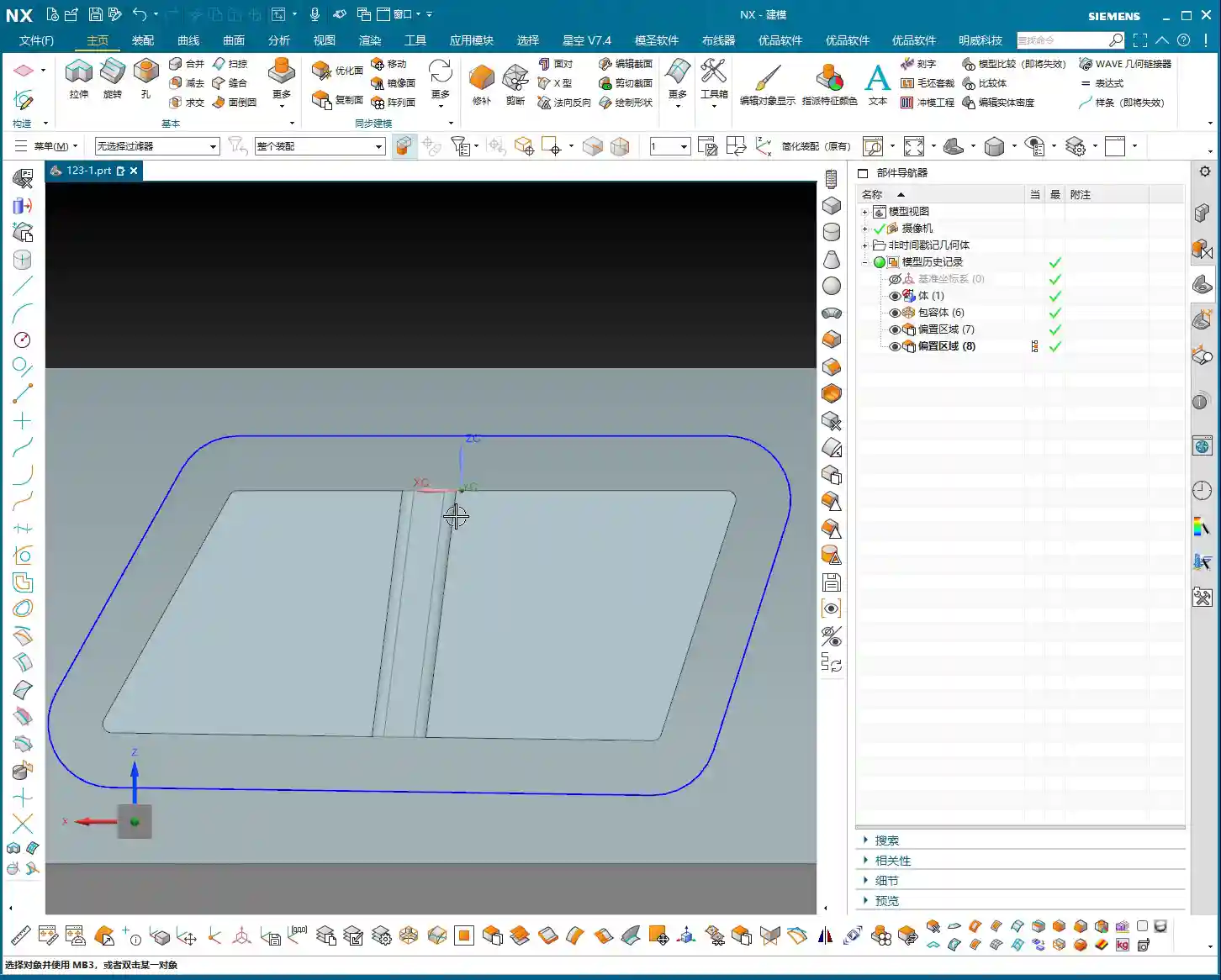
    With the sidewalls clarified, let’s address the bottom surface. This area cannot be overlooked, as it directly impacts the overall flatness of the part.

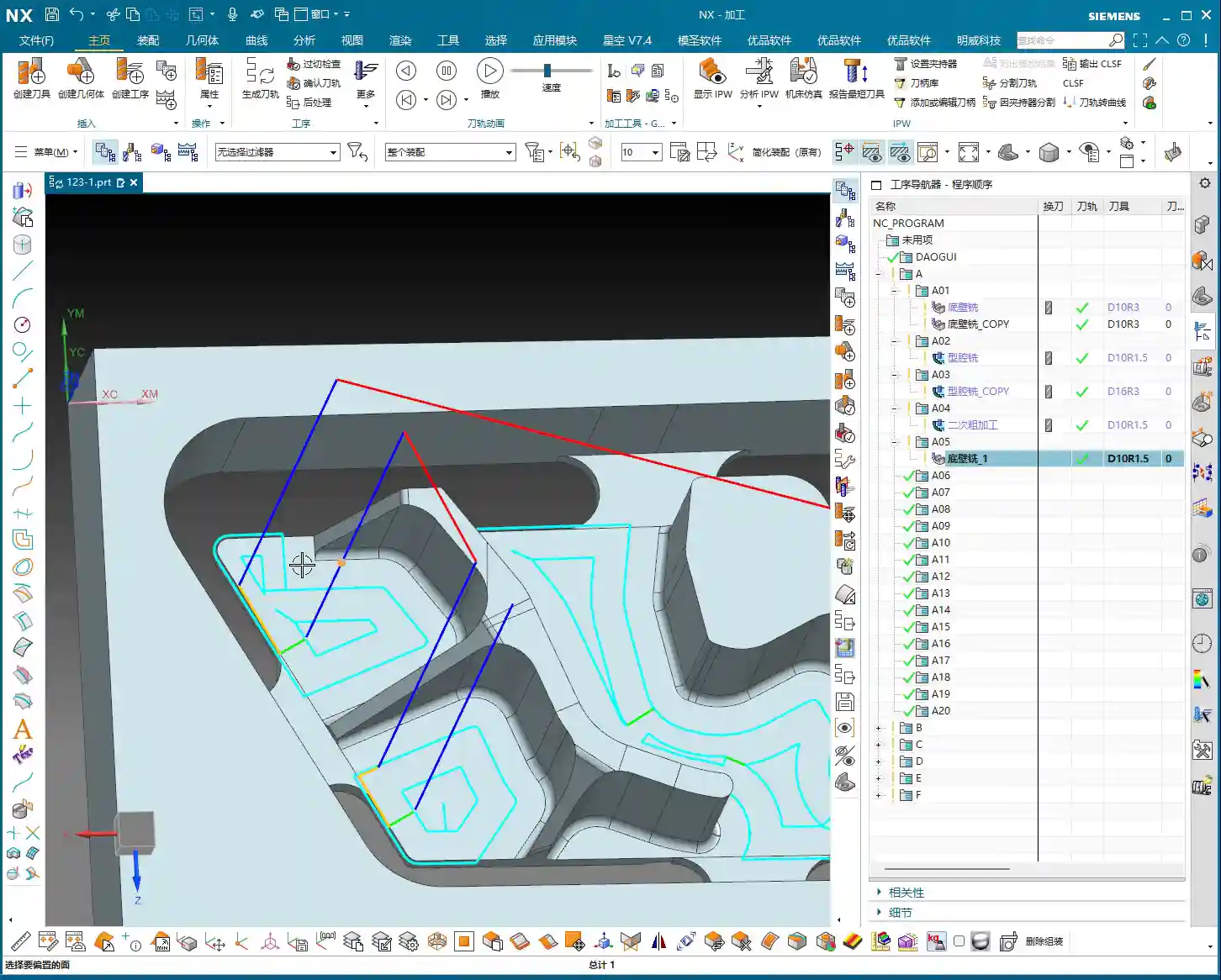
    Bottom Surface Program Creation and Entry Strategy

    Insert a new program, focusing on the bottom surface first. When selecting faces, make sure to select all bottom surfaces. For the entry strategy, since the sidewalls have already been machined, we can consider **entering from outside the part**. This way, the tool doesn’t have to struggle to plunge into the material, resulting in smoother cutting and extended tool life.

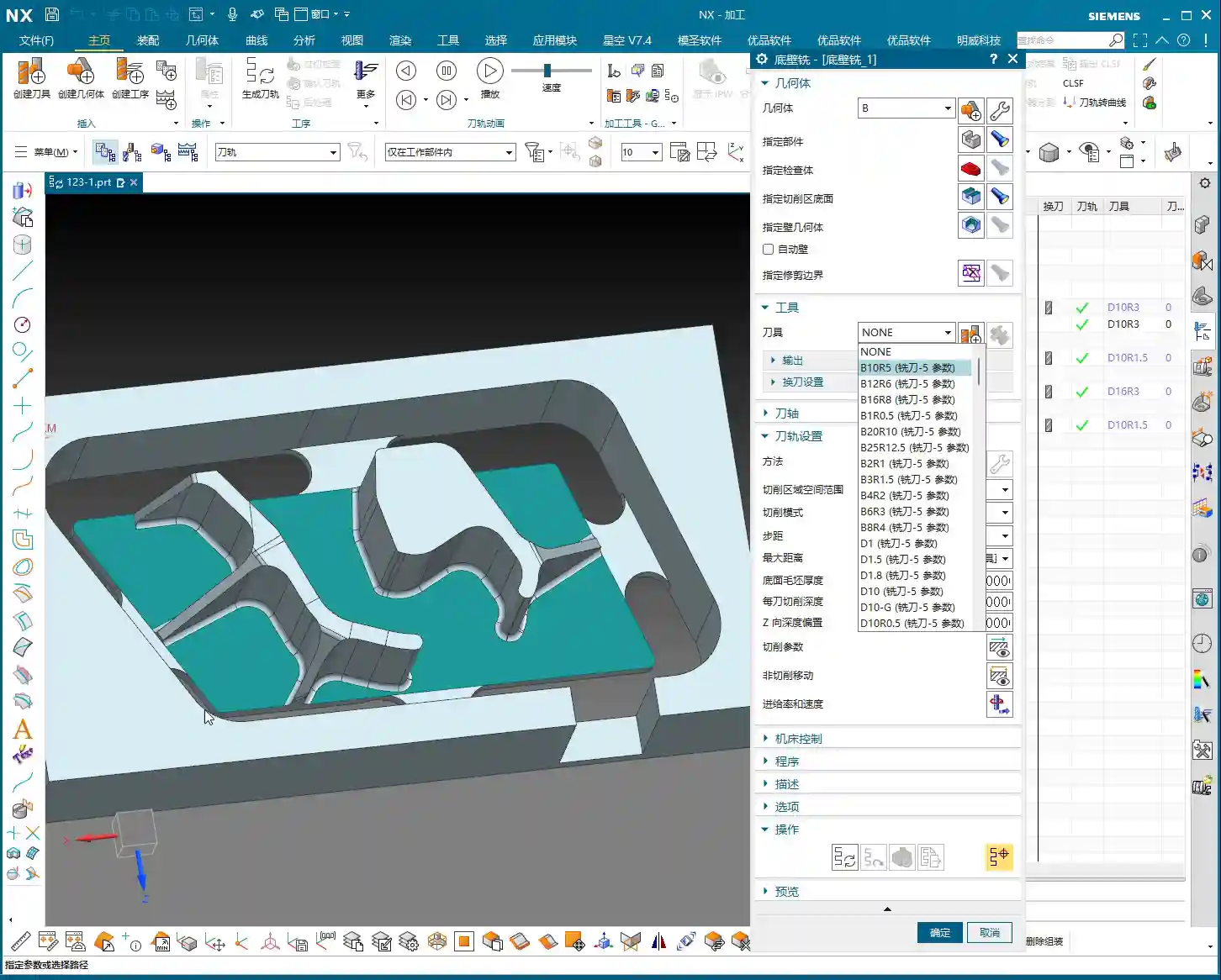
    Tool and Machining Parameter Settings

    For bottom surface machining, I recommend using an **R1.5 ball end mill** (or a flat end mill with a corner radius, depending on specific requirements).

    • **Depth of Cut (Stepdown):** This parameter is crucial, directly affecting surface quality and machining efficiency. I heard you set it to **0.1mm**. This is very fine, suitable for **finishing passes**. For **roughing**, you would need to increase it.
    • **Stepover:** Set this to **percentage stepover**, with the direction **inward**. This causes the toolpath to progress from outside to inside, layer by layer, resulting in more stable cutting.
    • **Angle Adjustment:** If the tool’s movement appears to ‘turn too much,’ you’ll need to adjust the angle. Elevate it slightly to allow the tool to move more freely, avoiding unnecessary cutting trajectories.
    • **Clearance Distance and Retract Height:** Let’s change the **clearance distance** to **0.5mm**. Also, a critical point: the stock allowance and retract height you mentioned earlier are mismatched; they need correction! Re-set the **sidewall stock allowance** to **0** so the tool doesn’t leave marks on the sidewall. The retract height should also be changed to **1mm** to ensure safety without retracting too high and wasting time.

    Sidewall Finishing Pass: Avoiding Tangency Surface Traps

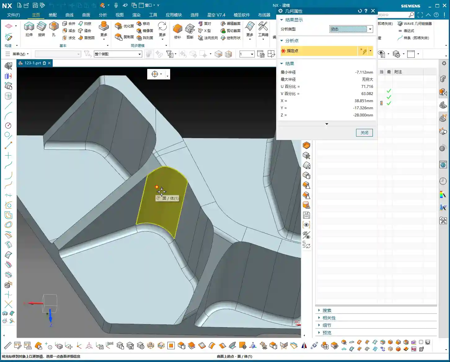
    With the bottom surface addressed, let’s return to thoroughly finish the sidewalls. The most common pitfall in this step is **face selection**, especially for complex faces with tangency relationships.

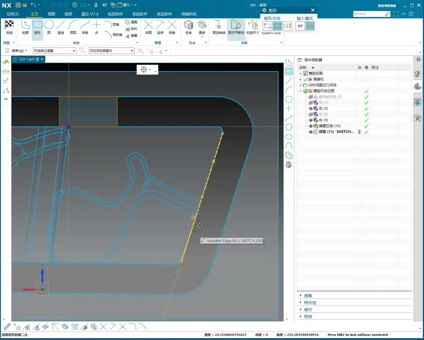
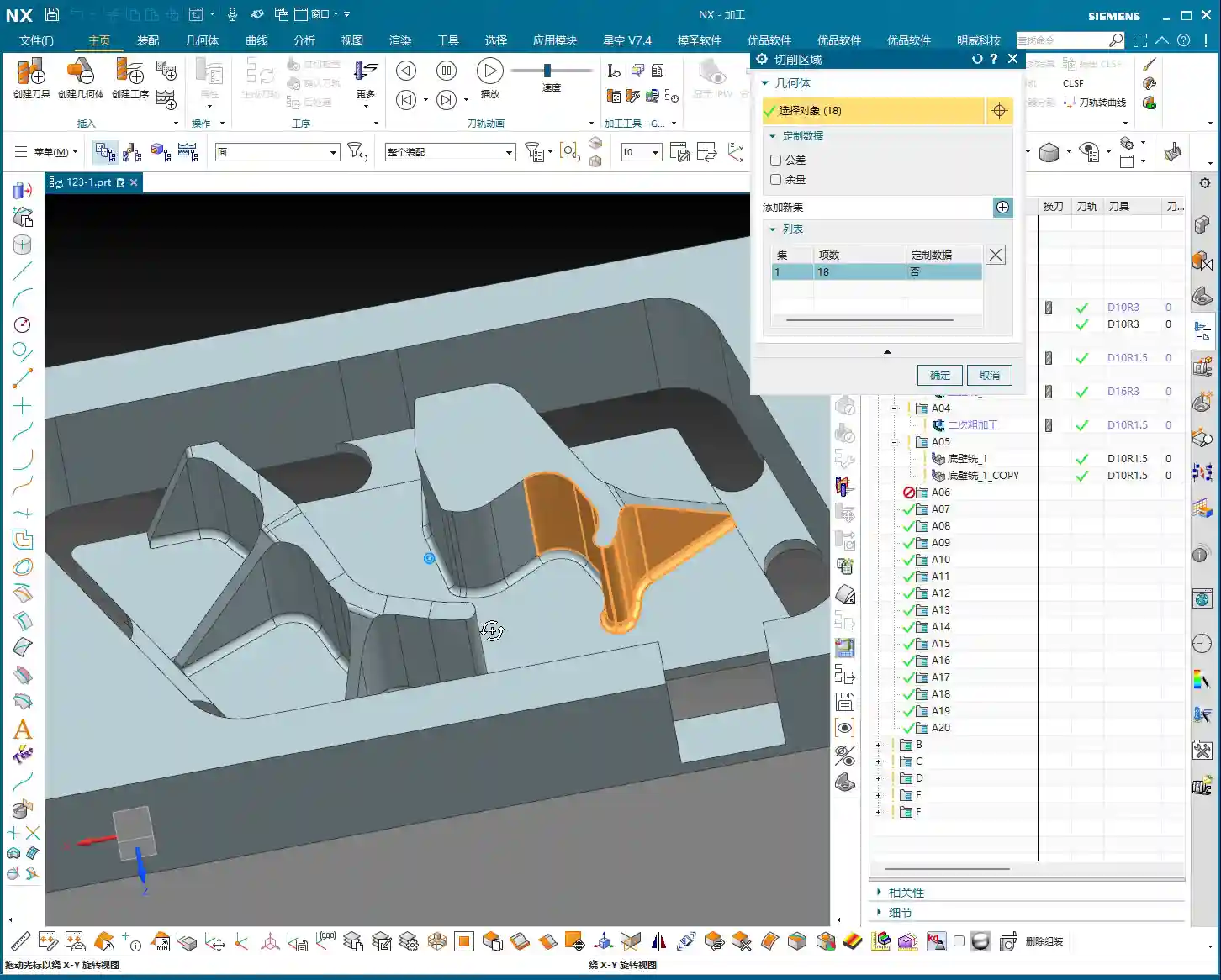
    How to Precisely Select Sidewall Faces

    You mentioned that if certain sidewall areas are incorrectly or poorly selected, problems will arise. This is especially true for **tangent faces**, where automatic software selection can easily include faces that shouldn’t be machined, causing more trouble. In such cases, **manual intervention** is essential!

    • **Better Manual than Incorrect:** If the software’s automatic face selection isn’t reliable, then select them **one by one!** Don’t be afraid of the hassle; a few minutes spent now is insignificant compared to reworking or scrapping a part. Accurately select all sidewall faces that require a finish cut.
    • **Toolpath Trimming:** Remember, in some areas, if you let the tool run freely, it will generate redundant toolpaths, or even cause a **tool crash**. Therefore, you must **trim the toolpath**. Directly ‘cut’ away areas that don’t require machining, or where interference might occur, to ensure a clean and safe toolpath.

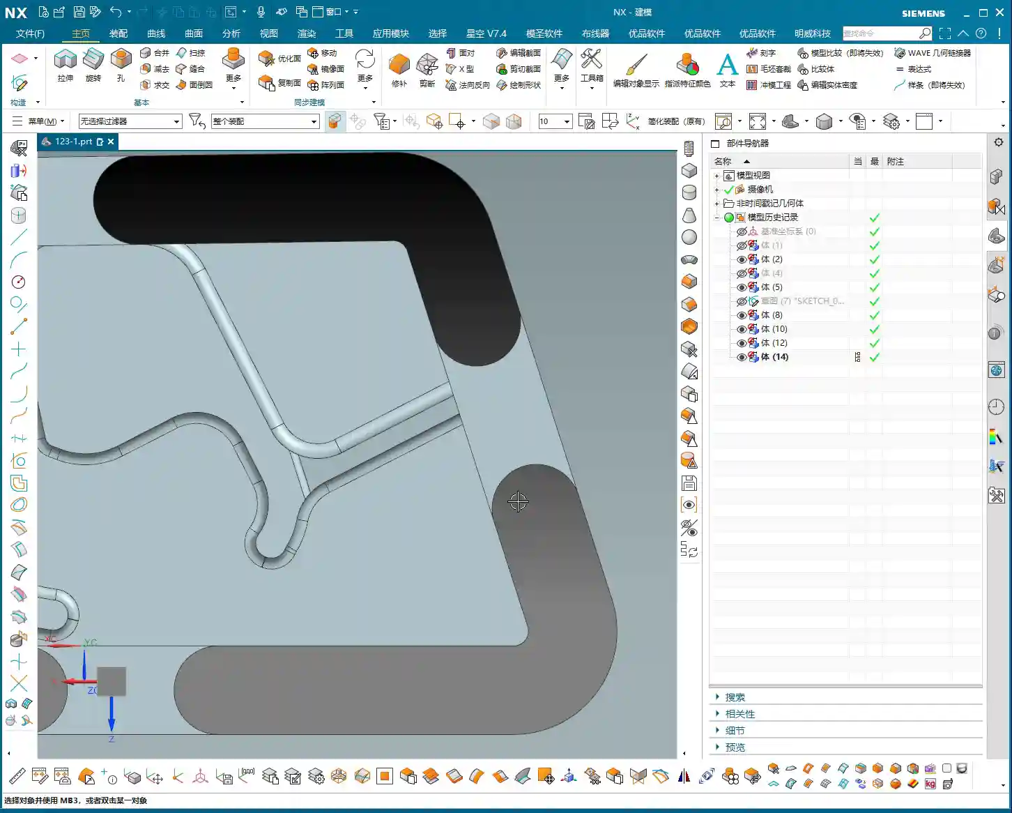
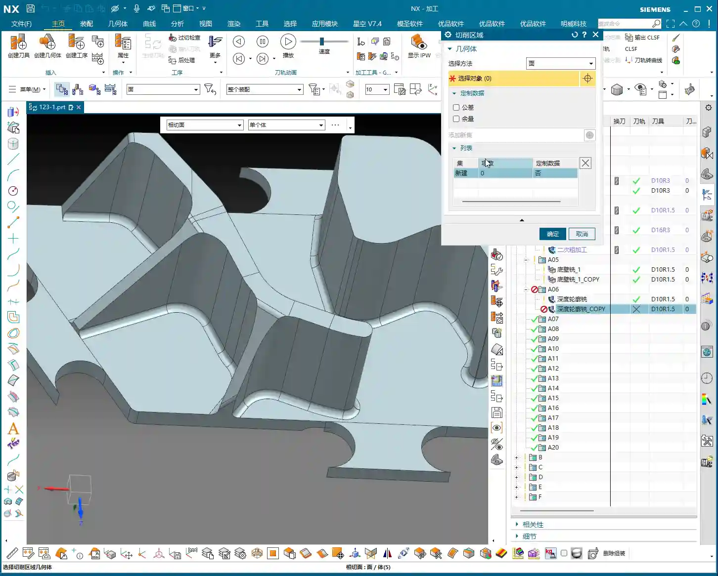
    Coordinating Subsequent Bottom Surface and Sidewall Finishing Passes

    We can duplicate the bottom surface **finishing pass** program, change the stock allowance to **0**, and let it completely finish the bottom surface. Then, perform another **finishing pass** on the sidewalls. For this sidewall **finishing pass**, continue to use the **D10R1.5 tool**, with a **1mm depth of cut** per pass. The goal is to allow the tool to finish all the way down to the bottom surface.

    • **Corner Radius Machining:** When encountering the small corner radii that were previously allowed for, you can adjust the corner radius parameter to **1.5mm** (or as per actual requirements). This step ensures smooth corner transitions, no burrs, and accurate dimensions.
    • **Safe Entry:** Tool entry must be safe; ideally, the tool should enter along the edge of the workpiece. This prevents interference and ensures machining stability.

    Toolpath Optimization: Practical Wisdom on Retracts and Extensions

    After finishing and generating the program, don’t rush to the machine. You still need to review the toolpath for any necessary optimizations; these are key factors affecting efficiency and final quality.

    Rational Setting of Retract Height

    You mentioned that the **retract height** is too high. This is a common issue! High **retracts** are purely a waste of time. Let’s change it to a **plane retract**, setting the **clearance distance** to **10mm** (or based on actual conditions, such as 5-10mm above the highest point of the workpiece). Remember, as long as it ensures no **tool crash**, keep the **retract height** as low as possible. Every second saved adds up; that’s how you gain efficiency!

    The Necessity of Toolpath Extension

    Another small detail is **toolpath extension**. Often, if you don’t extend the toolpath slightly, for example, by **0.3mm or 0.5mm**, it’s easy to leave a tiny unprocessed area at the end of the tool’s path. Don’t underestimate these few tenths of a millimeter; they can affect the entire surface finish and even lead to out-of-spec dimensions. So, when this happens, directly extend the toolpath slightly to ensure the tool fully cuts off the workpiece and completely cleans the area.

    Balancing Efficiency and Tool Life

    Finally, let’s talk about efficiency. For sidewall **finishing passes**, if you find a **1mm depth of cut** too slow and the stock allowance is relatively large, you can certainly take more passes, reduce the **depth of cut** per pass, and increase the feed rate. These adjustments are always based on actual conditions; there are no rigid, one-size-fits-all rules. Our goal is to maximize efficiency and minimize tool wear while maintaining quality. That’s how you make money, understand?

    Summary: Pitfall Avoidance Guide

    • **Precise Stock Allowance Settings:** Don’t assume no stock allowance means it’s finished. Sometimes, leaving a minute allowance (e.g., **0.01mm**) can save significant trouble for subsequent **corner cleanup** and ensuring accuracy.
    • **No Laziness in Manual Face Selection:** When dealing with complex **tangent faces** and automatic software selection is unreliable, decisively switch to **manual face selection**, picking them one by one to ensure foolproof results.
    • **Toolpath Trimming is Essential:** Promptly trim redundant or risky toolpaths to prevent **tool crashes** and inefficient cutting.
    • **Rational Retract Height:** While ensuring safety, minimize **retract height** as much as possible. These small savings add up, improving overall machining efficiency.
    • **Toolpath Extension Prevents Uncut Areas:** For critical toolpath regions, remember to extend them appropriately to eliminate any unprocessed ‘dead spots’.
    • **Parameter Adjustment Based on Observation:** No matter how good the software simulation looks, ultimately you must observe the **cutting sparks** and the actual workpiece condition, flexibly adjusting parameters based on experience.

    👤 About the Author:
    The author is a veteran CNC machining professional with 15 years of industry experience, specializing in UG NX programming. This article is an original work representing personal practical insights.

    ⚠️ Copyright Notice: Unauthorized reproduction or distribution without prior communication is strictly prohibited.

  • Efficient Connecting Rib Modeling and Machining in Siemens NX: Master Wang Teaches You How to Avoid

    📝 Key Takeaways: ** Master Wang discusses efficient connecting rib machining in Siemens NX. He analyzes the part blank and plans roughing and finishing tools (D12 R1.5 for R7 fillets, D20 for Roughing, D10 for cut-off). He demonstrates Siemens NX offset curves and surface replacement, emphasizing a 12mm offset to avoid air cuts. He teaches connecting rib sketching, extrusion, and arc smoothing techniques, combined with standardized layer management, to achieve efficient and precise machining, sharing practical experience in avoiding pitfalls.

    Hello everyone, I’m Master Wang. Today, let’s break down an interesting task: how to properly machine a component’s connecting ribs using Siemens NX. Not only do we need to machine them, but we need to do it precisely and efficiently. Listen up, this isn’t some theoretical mumbo jumbo you read in a textbook; this is all hard-earned expertise from the shop floor!

    Step One: Component Overview and Machining Strategy

    The component we’re working with—while I might call it a “frame”—is actually a relatively small component. At first glance, it’s roughly 100+ by 50+ millimeters (approx. 4 x 2 inches), so not large. The customer provided a large blank, approximately 30 millimeters (approx. 1.2 inches) oversized compared to the finished part. Therefore, we need to understand this upfront: Sufficient material allowance for Roughing must be provided, but not blindly; it depends on the actual situation.

    My standard practice is to machine the bottom face first, then flip the part to machine the top face. Why? Once the bottom face is flat, it’s easier to establish datum features for the top face, and Clamping will be stable. This part has flat top and bottom surfaces; one side is straight, and the other has a slight taper. For parts of this geometry, we typically use a “sequential machining” approach in our workshop—machining one section first, then using it as a datum for machining the next.

    Upon analysis, all major faces of this component are flat; in Siemens NX, the surfaces appear uniformly green (indicating good quality). There are no particular pitfalls to watch out for. Those oddly shaped, uneven surfaces we’ve encountered before are not present here. So, at a macro level, we have a good grasp of the situation.

    Step Two: Tool Selection and Roughing/Finishing Strategy

    Before we start, tool selection is of paramount importance. It’s like going to war: if you have the wrong weapon, even the best skills are useless!

    Fillets and Tool Radii

    Let’s take a close look at the part’s fillets. Most fillets are R1.5. However, at the connecting rib, a “Distance Analysis” in Siemens NX reveals it’s R7! Two R7s add up to 14mm (approx. 0.55 inch). So, using a D12 R1.5 (diameter 12mm, corner radius 1.5mm) ball end mill or corner radius end mill for a Finishing pass on the side walls and bottom is perfectly adequate, no problem.

    Roughing and Cut-off Tools

    For Roughing, we can use a slightly larger tool. The part is roughly 26mm (approx. 1 inch) wide, so a D20 (diameter 20mm) flat end mill or roughing end mill will run quickly and stably. As for the final cut-off operation, we typically use a D10 (diameter 10mm) tool. Keep this in mind, as it will allow for pre-planning during subsequent modeling.

    Step Three: Siemens NX Connecting Rib Modeling and Offset Techniques

    Now, for the main event—how to model these connecting ribs and prepare them for machining. Don’t just think a few clicks in Siemens NX will do the trick; there are many nuances here!

    Generating the Outer Contour

    First, we need to address the part’s outer contour. Using Siemens NX’s “Offset Curve” function, offset the lines on the model outwards. How much to offset is critical! If you use a 10mm (diameter 10mm) tool for cut-off and offset by 10mm, the tool centerline will be precisely on the contour line, resulting in zero allowance. The finish might be poor, or the tool might even chatter/gouge. Therefore, we offset by 12mm (approx. 0.47 inch). This allows the tool centerline to run externally, providing sufficient material allowance or leaving space for a Finishing pass, ensuring cutting stability.

    After offsetting, any previous auxiliary lines are no longer needed; delete them to keep the model clean. Then, remember to smooth the offset contour lines with fillets (e.g., R5) to avoid stress concentration from right-angle cutting. This benefits both the tool and the part.

    Drawing and Extruding the Connecting Rib

    Next, let’s draw the connecting rib. For this connecting rib, we’ll use the “Sketch” function to draw a rectangle on a reference plane. When drawing, ensure it extends to the part’s edge, as we’ll use it to “create geometry” later. Drawing it slightly larger is fine; it will be cut away eventually. The key is that its shape must be reasonable, providing connection and support.

    After sketching, directly “Extrude” to create a solid body. If the extrusion height wasn’t precisely measured beforehand, just extrude it to an approximate thickness for now. This is where Siemens NX’s power lies—it can be adjusted later. After extrusion, you might find the top face of the connecting rib isn’t at the same height as other top faces of the part. No problem. Simply use the “Replace Face” function to replace the connecting rib’s top face with the part’s datum top face. This ensures all surfaces are on the same plane, saving you the hassle of multiple measurements and adjustments.

    Finally, if any auxiliary curves generated during the extrusion are no longer needed, delete them. Can’t delete them? Throw them into a junk layer (like my 252 layer)—out of sight, out of mind! These are all small tips for boosting work efficiency.

    Step Four: Surface Handling and Parameter Management

    Surface handling and parameter management are easily overlooked but highly critical aspects of Siemens NX operations.

    Surface Smoothing and Splitting

    When modeling connecting ribs, I recommend using arcs to connect linear segments for smoother transitions. This isn’t just for aesthetics; it’s crucial for machining. Smooth transitions enable more fluid tool engagement, reduce Chatter, extend tool life, and improve the part’s surface finish. Don’t underestimate this small arc; it can save you significant polishing and grinding time!

    Additionally, for areas requiring independent machining, such as the bottom of the connecting rib, we can use the “Split Face” function to divide a large face into several smaller ones. This allows for more precise toolpath control during programming—for instance, machining only this small area instead of traversing the entire face. This is highly valuable for controlling machining boundaries and optimizing efficiency.

    Layer Management and Model Standards

    Siemens NX’s layer management is an excellent feature; you must use it! My practice is to place:

    • Blanks/Raw Material on layer 100
    • Finished Parts on layer 10
    • Connecting Ribs on layer 200
    • Unused auxiliary lines and junk features on 252 (junk layer)

    This way, the model structure is clear at a glance; just activate the layers you need, avoiding model clutter and difficulty in searching. Don’t underestimate these details; standardized layer management can double your work efficiency and facilitate collaborative work. It’s a cornerstone of efficient teamwork and an embodiment of “standardization” in industrial product management and promotion, which can lead to a better market reputation for your products!

    Summary: Pitfall Avoidance Guide

    1. Proper Blank Allowance is Crucial: Never underestimate the raw material allowance. It directly impacts Roughing efficiency and subsequent machining accuracy. Too little, and you can’t cut; too much, and you waste material and time.
    2. Matching Tool Selection is Key: Choose tools based on the part’s fillets, dimensions, and operations (Roughing, Finishing, cut-off). Incorrect tool selection can lead to low efficiency at best, and scrapped workpieces or broken tools at worst. For example, offsetting for cut-off by 12mm instead of 10mm is to provide the tool with sufficient cutting space, preventing it from cutting directly on the contour line, which could lead to unstable cutting or even breakage.
    3. Smooth Connecting Rib Modeling: Proper transitions between lines and arcs not only enhance aesthetics but are also critical for ensuring smooth machining and reduced tool wear.
    4. Flat Surfaces are Fundamental: Make full use of functions like “Replace Face” to ensure all machined surfaces are on the same plane, avoiding issues like secondary Tool Offsetting or accuracy problems caused by uneven surfaces.
    5. Layer Management is Indispensable: Develop good layer management habits. This not only makes finding files easier for you but also allows colleagues to quickly take over. This is the cornerstone of efficient teamwork and an embodiment of “standardization” in industrial product management and promotion, which can lead to a better market reputation for your products!

    **[EXCERPT]**
    Master Wang discusses efficient connecting rib machining in Siemens NX. He analyzes the part blank and plans roughing and finishing tools (D12 R1.5 for R7 fillets, D20 for Roughing, D10 for cut-off). He demonstrates Siemens NX offset curves and surface replacement, emphasizing a 12mm offset to avoid air cuts. He teaches connecting rib sketching, extrusion, and arc smoothing techniques, combined with standardized layer management, to achieve efficient and precise machining, sharing practical experience in avoiding pitfalls.

    👤 About the Author:
    The author is a veteran CNC machining professional with 15 years of industry experience, specializing in UG NX programming. This article is an original work representing personal practical insights.

    ⚠️ Copyright Notice: Unauthorized reproduction or distribution without prior communication is strictly prohibited.