📝 Key Takeaways: **
Siemens NX Contour Spiral Milling: A Practical Guide
Listen up, fellas! I’m Master Wang. Today, we’re diving into contour spiral milling…
Listen up, fellas! I’m Master Wang. Today, we’re diving into contour spiral milling in Siemens NX. This feature gets a lot of use on the shop floor. Don’t let its similar interface to standard plane contour milling fool you; the real intricacies aren’t always clear in textbooks. With 15 years of hands-on experience, I can tell you: use spiral milling right, and you’ll double your efficiency; mess it up, and you’ll be dealing with **tool rubbing**, scrapped parts, and more!
Contour Spiral Milling: Practical Fundamentals
Within plane contour milling, there’s a function called “Contour Spiral.” Simply put, it’s for **spiral milling**. While it looks quite similar to conventional plane contour milling, its core requirements and application scenarios are distinctly different.
Core Concept: Spiral Machining and Closed Contours
First, remember this: the core requirement for spiral machining is that the machining contour must be closed! Just like drilling or pocket milling, you need to define a complete boundary. If you select only a single line, an open corner, or even an unclosed contour, spiral machining will fail. The program might generate toolpaths, but running it on the machine will certainly lead to issues because the tool won’t know where to **stepdown** spirally and might wander erratically. External contours, as long as they are fully closed, can also be processed with spiral milling.
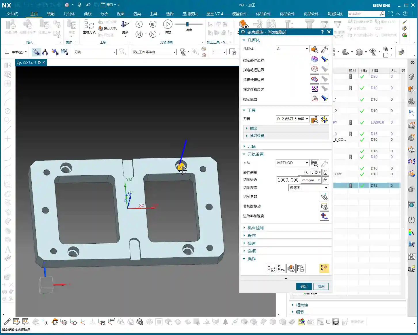
Siemens NX Operation Path and Interface

Head directly to “Insert” -> “Operation” to find “Contour Spiral.” Once you click in, you’ll notice its main interface is almost identical to plane contour milling, with mostly similar parameter options. But don’t be fooled by appearances; subtle adjustments here determine machining quality and efficiency.
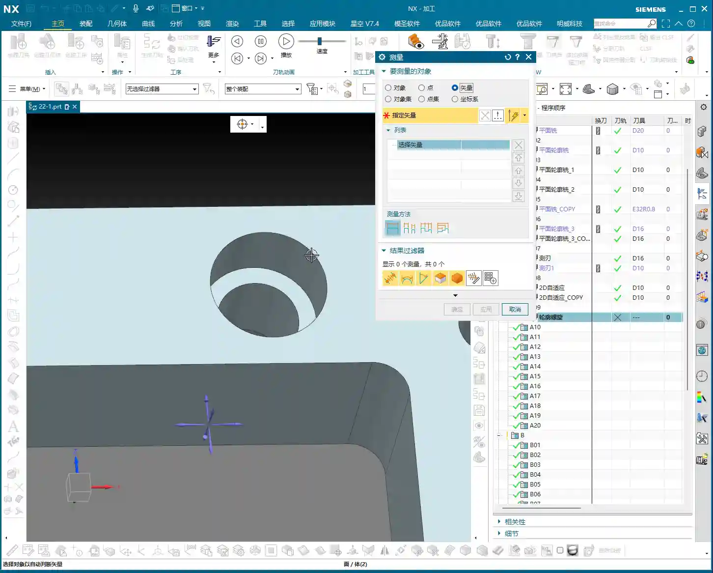
Workpiece Measurement and Tool Selection
Let’s say we need to machine a 20mm diameter hole (10mm radius). Tool selection here requires careful consideration. If you use a D12 end mill, it can efficiently mill out the hole within a single spiral path. This isn’t random tool selection; it must be based on the hole diameter and stock allowance to ensure the tool can cut effectively, not just picking a small tool for easier path generation.
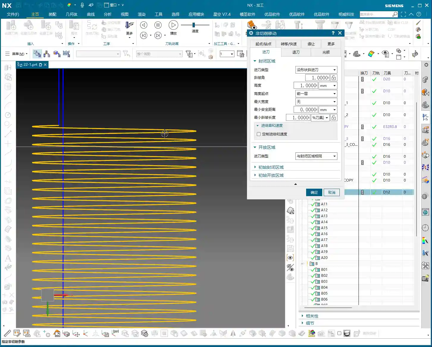
The Secret of “Yellow Line Spiral”
After program generation, you’ll see the toolpath simulation in Siemens NX, primarily composed of “yellow lines.” In Siemens NX, these yellow lines represent engaged cutting paths, meaning the tool is continuously cutting, moving spirally downwards, inwards, or outwards until it reaches the set **depth of cut**. This is somewhat similar to dynamic milling, both aiming to ensure continuous tool engagement, reduce air cuts, and boost efficiency.

Key Parameter Tuning and Optimization
The essence of spiral milling lies in the precise tuning of several key parameters. If these aren’t set correctly, you’ll face low efficiency at best, and scrap your workpiece at worst.
The Art of the Ramp Angle
In the “Non-Cutting Moves” options, there’s a crucial parameter called “Ramp Angle”. This angle dictates the aggressiveness of the tool’s spiral **stepdown**.
* A larger Ramp Angle means greater axial material removal per pass (higher effective **Depth of Cut**). Theoretically, machining speed is faster, but cutting load is also higher, leading to quicker tool wear or even chipping.
* A smaller Ramp Angle means less axial material removal per pass, resulting in a denser machining path, smoother cutting, and better surface quality, but it also takes longer.
In practice, you need to adjust this flexibly based on material hardness, tool type, and workpiece precision requirements. For example, for contours with long perimeters, you should set a smaller **Ramp Angle**, such as 0.1 degrees, to ensure reasonable axial material removal per pass and stable cutting.
Ramp Length and Tool Matching

Another easily overlooked detail is “Ramp Length.”
* If you’re using a solid carbide end mill (without inserts), setting a small ramp length, even 1%, is usually fine because its entire cutting edge can engage.
* However, if you’re using an indexable insert tool, pay close attention! The bottom of the insert is non-cutting. If the ramp length is too small, the insert bottom can easily rub against the workpiece, causing friction and **chatter**. At best, this damages the tool; at worst, it causes chipping or even scraps the workpiece. In such cases, I usually recommend setting the ramp length to 50% of the tool diameter. If Siemens NX prompts that the program cannot be generated, it means your parameters are unreasonable, and the tool is highly likely to **rub** or **gouge** the material.
Efficiency Secret for Multi-Hole Machining
If you encounter multiple identical holes requiring spiral machining, don’t be foolish and create a program for each one individually. Siemens NX has a solution:
1. Go into the “Part Boundaries” option.
2. Select “Add New Geometries.”
3. Change the selection type from “Face” to “Curve”.
4. Then, sequentially select the inner contour curves of all holes that need machining.
5. Click the middle mouse button to confirm, then click “OK” to generate the toolpath.
This way, one program handles all holes, saving time and effort—that’s how we achieve efficiency!
Scope of Application: More Than Just Round Holes
Don’t assume spiral machining is only for milling round holes. As long as it’s a closed geometric shape, whether square, triangular, or even an irregular contour, you can use contour spiral machining. The key is:
* It must be closed! If your contour is originally open but you want to use spiral machining, you’ll need to manually “extend” it to form a closed path. This prevents the tool from “air cutting” and ensures it quickly completes the extended portion.

Summary: Pitfall Avoidance Guide
Alright, here are the crucial points, learned through hard lessons:
1. The contour must be closed! This is the foundation of spiral machining; misunderstand this, and you’re asking for trouble.
2. Beware of spiral retract collision! This is the most common and dangerous pitfall. Especially when machining through holes, as the tool reaches the final **Depth of Cut**, the central slug (waste material) might drop. If the tool retracts along an arc (default setting), it will swing sideways. If the falling slug hasn’t fully detached, it could collide with the retracting tool! The result: tool chipping, scrapped workpiece, or even machine damage.
* **Solution:** Always check the retract type in “Non-Cutting Moves.” Change the default “Arc Retract” to “Lift” (vertical retract). This way, after completing the cut, the tool will lift straight up vertically, avoiding potential falling slugs. Safety first! I usually set a 3mm lift; that’s generally sufficient.
3. Ramp length must match the tool type! For indexable insert tools, provide sufficient ramp length (e.g., 50%); for solid carbide or custom-ground tools, it can be smaller.
4. Adjust ramp angle according to contour perimeter! The longer the contour, the smaller the ramp angle should be to ensure stable cutting.
5. Be flexible with stock allowance settings! While spiral machining is typically for **roughing**, if you aim for high precision or need to leave stock for a subsequent **finishing pass**, you must precisely set the stock allowance parameters. Don’t assume it’s **roughing** and completely omit stock, unless you’re sure a single pass is sufficient and meets precision requirements. This depends on your actual workpiece requirements and subsequent operations.
Remember these points, and spend time observing the cutting sparks at the machine, not just relying on software simulations—practice makes perfect!
👤 About the Author:
The author is a veteran CNC machining professional with 15 years of industry experience, specializing in UG NX programming. This article is an original work representing personal practical insights.
⚠️ Copyright Notice: Unauthorized reproduction or distribution without prior communication is strictly prohibited.