📝 Key Takeaways: ** Master Wang provides a hands-on guide to practical techniques for single-pass Corner Cleanup in Siemens NX. This focuses on understanding the logic behind simplified parameters, distinguishing between highlighted regions and actual toolpaths, avoiding common pitfalls of relying solely on software simulations, and ensuring efficient and precise Corner Cleanup. **
Hello everyone, I’m Master Wang. Today, let’s continue discussing practical applications. As far as the previous “Main Region” discussions go, I believe we’ve covered everything, mainly area management and some fundamental considerations. Now, let’s jump straight to the core topic: Single-Pass Corner Cleanup.
Single-Pass Corner Cleanup in NX: Fundamental Concepts and Key Parameters
Command Overview and Application Scenarios
Listen up, this Single-Pass Corner Cleanup, as the name implies, is about using one tool for one pass to clean out the material left behind in corners that larger tools couldn’t reach. Often, after roughing with a large tool, there’s always some residual material in the corners. That’s when you need a smaller tool for Corner Cleanup. This command is specifically designed for that job.
Parameters like ‘Angle,’ ‘Minimum Cut Length,’ and ‘Merge Distance’ have been thoroughly explained when I covered deep slot Contour Milling and Surface Milling. We won’t delve into them again here. If you don’t remember, go back and review your previous notes. These are fundamental skills you can’t afford to forget.

Cutting Strategies for Steep and Non-Steep Regions
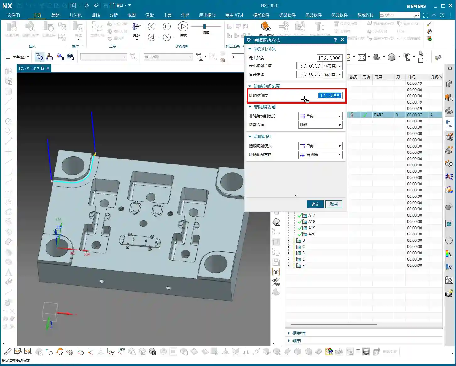
Let’s go straight to the ‘Steep Area Angle’ parameter; this is crucial. For example, if it’s set to 65 degrees. What does this mean? It means that when the workpiece’s sloped surface angle is less than 65 degrees, it will not machine it; toolpaths will only be generated for Corner Cleanup in steep areas that are greater than or equal to 65 degrees. This follows the same logic as our previous discussion on defining ‘steep’ and ‘non-steep’ regions in Surface Milling.
As for cutting methods in ‘non-steep regions,’ such as ‘One Way,’ ‘Climb,’ ‘Conventional,’ or ‘Mixed,’ you should all be clear on those by now, so I won’t belabor the point.
Specificity of Single-Pass Corner Cleanup
I need to emphasize something here: because it’s ‘Single-Pass’ Corner Cleanup, as the name suggests, it only makes one pass. Therefore, for many parameters, such as cutting direction, simply selecting ‘One Way’ is sufficient. It’s not like other complex milling strategies that present you with a plethora of options. In this operation, fewer options actually make it simpler; you don’t need to overthink it. Similarly, for steep region cutting strategies, ‘One Way’ or ‘Same as Non-Steep’ is often enough, or even ‘None’ will work, because it’s just one pass; there aren’t many fancy variations.
Master Wang tells you, for this command, relatively few parameters need modification; most of the time, the defaults are fine. Because its core purpose is: one cleanup pass! To remove the residual material from those corners.

In-depth Analysis: The Nuances of Multi-Pass Processing in Single-Pass Corner Cleanup
Practical Interpretation of Multi-Pass Processing
Although it’s called ‘Single-Pass Corner Cleanup,’ it also includes a ‘multi-pass’ option. You might ask, isn’t that contradictory? Listen closely, this is where some ‘book-smart’ knowledge won’t cut it.
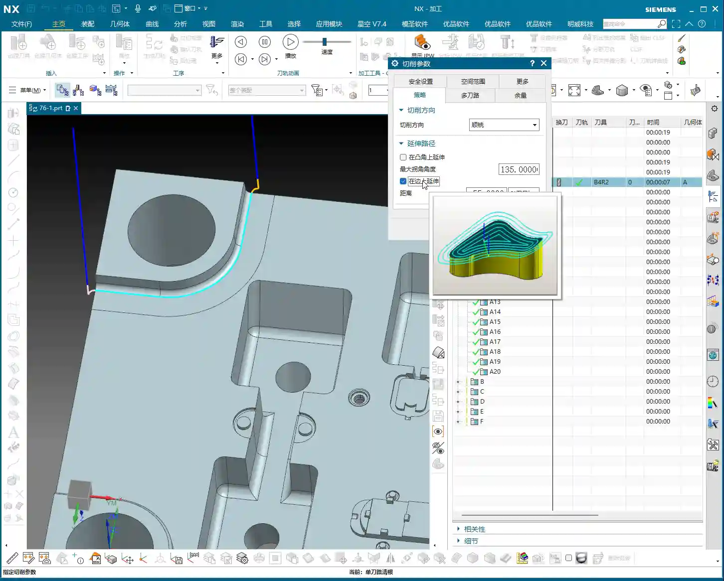
For example, if you’ve set up multi-passes with a total stock of 10 mm and a Depth of Cut (DOC) of 1 mm per pass. How will it proceed? It won’t simply cut layer by layer in the Z-axis direction like conventional machining. Instead, it will generate multiple passes that spread outward in an arc shape, based on the geometry of the corner you are cleaning up. This means if your corner has a radius, it will follow that radius, expanding outward with each successive pass, not just extending in the Z-direction. Don’t be fooled by the simulated toolpaths in the software and think it’s like regular Z-level machining; you’d be mistaken!
This approach is designed to better clean irregular or filleted residual areas, allowing the tool to conform more closely to the workpiece shape during cleanup. So, don’t be surprised when you see the toolpath expand in concentric arcs; it’s precisely extending the Corner Cleanup outward according to your fillet geometry.

Misconception Warning: Yellow Trajectory ≠ Actual Toolpath
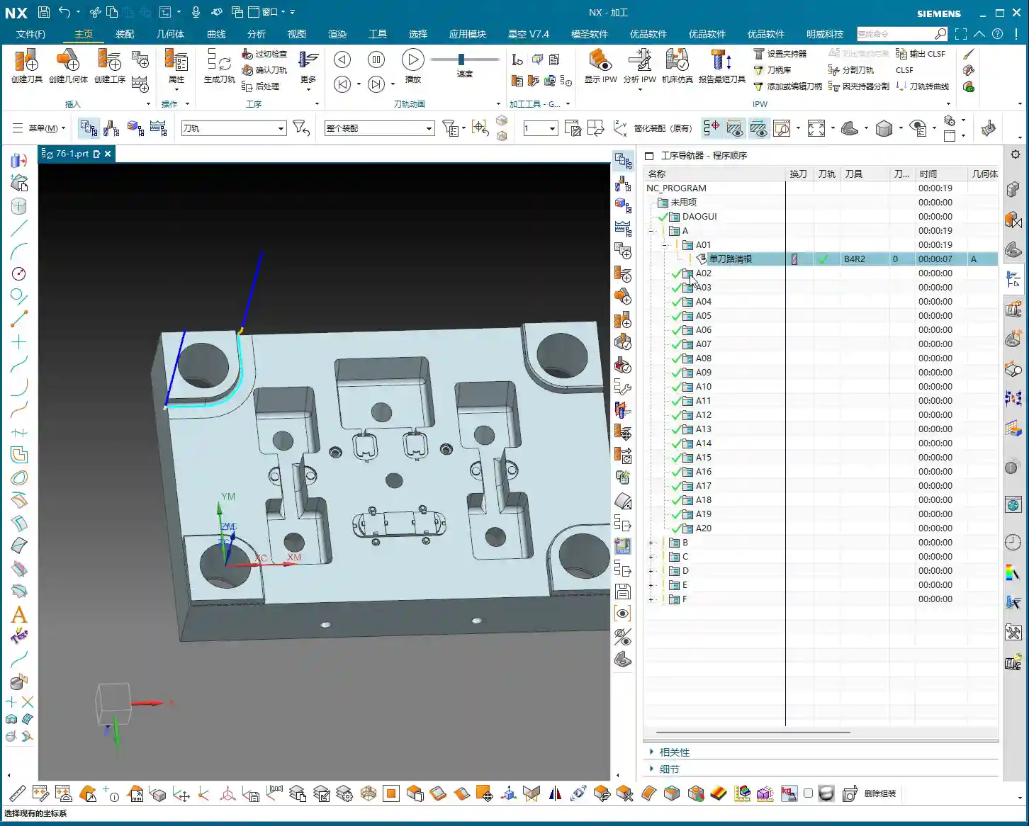
Select an area and generate the program, and you’ll see a bunch of yellow trajectory lines. Many new apprentices, seeing all this yellow on the screen, immediately assume it’s all toolpath. Big mistake! Listen up, this is a major pitfall.
Those yellow lines are merely areas that the software has highlighted as ‘potential toolpath generation’ regions, or rather, the reachable range for the tool. However, the true toolpath is only counted where the tool actually engages and cuts material. If you replay the program, you’ll see that in some areas marked yellow, the tool never actually descended – that’s not a toolpath! It’s just telling you there might be material there, and theoretically, the tool could reach it, but in actual machining, due to unmet conditions or simply no remaining stock, it won’t generate a real cutting toolpath.
So, don’t just look at the yellow lines from the software simulation; you need to see the cutting sparks, to confirm if the tool is truly engaging and doing work! This is practical experience; textbooks don’t always go into this much detail.
Practical Demonstration: Tool Selection and Path Generation

Impact of Tool Selection on Corner Cleanup Effectiveness
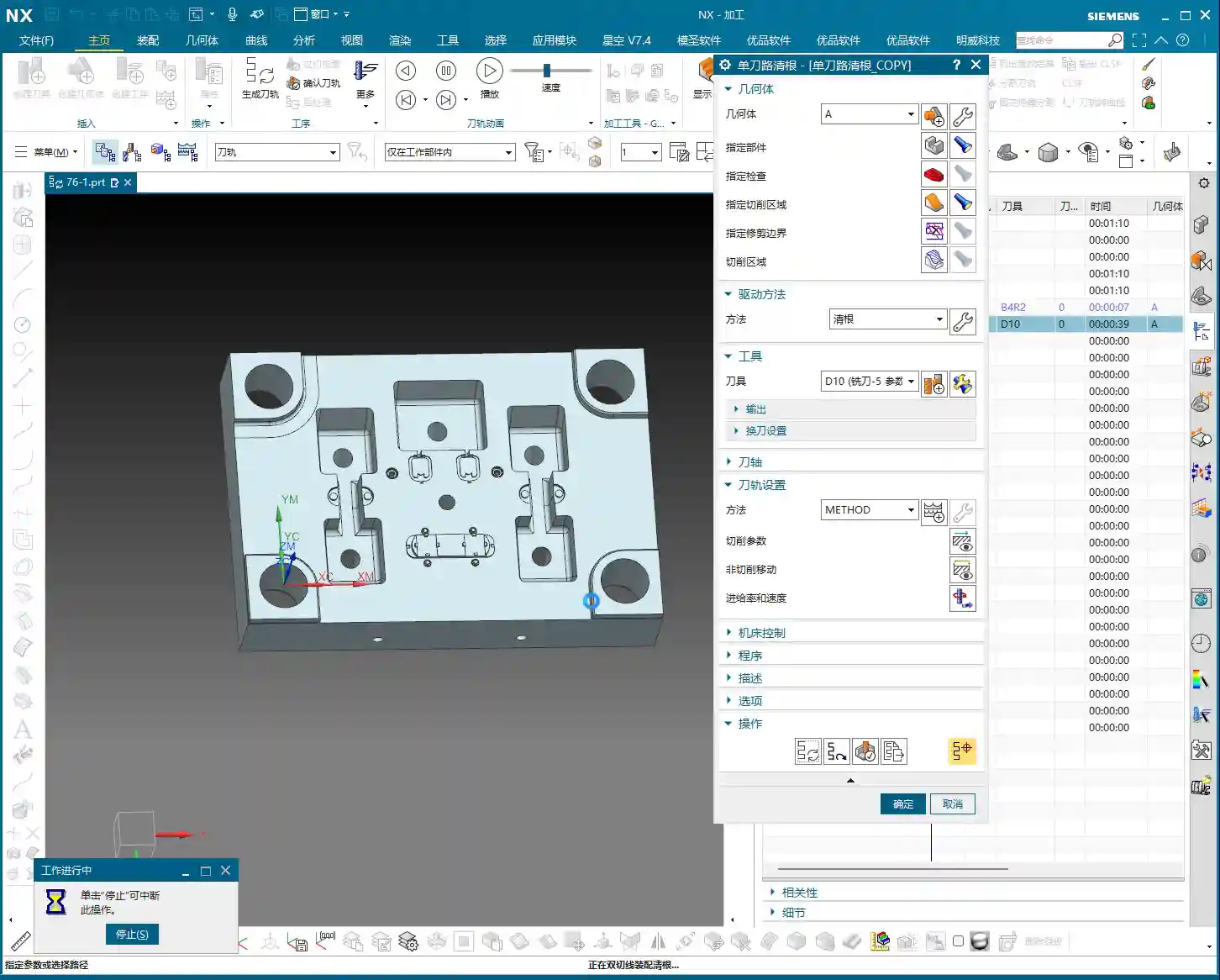
Let’s try switching tools. For instance, if I use a D10 (10mm diameter) tool for Corner Cleanup. You’ll notice it also follows the contour of the selected area, making one pass. It will make a Finish cut around all qualified edges. Both the outer contour here and the small corner there will be machined. Of course, if that corner isn’t clean enough with a D10 tool, then you’ll need to switch to a smaller tool – D6, D4, or even D2, depending on the actual requirements.
The core of this command is ‘Corner Cleanup,’ so it will try its best to clean along the contour lines. Sometimes, even if a corner has a fillet at the bottom, or no fillet at all, as long as it’s within the designated region, it will attempt to generate a toolpath. But whether it genuinely cuts material depends on the actual remaining stock and the tool size.
Toolpath Generation and Effects of Full-Area Corner Cleanup
If we select the entire workpiece as the Corner Cleanup region and then generate toolpaths. You’ll find that the program becomes very extensive and messy. This is because it will attempt to clean all internal contours, external contours, and every ‘corner’ it can find, using the single-pass method. The resulting toolpaths will look dense and highly complex.
However, this also highlights its ‘Corner Cleanup’ characteristic: leaving no corner untouched. Some small grooves might appear ‘overcut,’ but that’s because the tool also makes a single pass through them. Therefore, when using this command, you must precisely select the areas requiring Corner Cleanup based on the actual situation, rather than selecting everything indiscriminately. Otherwise, efficiency will suffer, and the program will be disorganized.
Summary: Pitfall Avoidance Guide
- Understand the Essence of ‘Single-Pass’: Its core principle is to make only one pass, so many complex parameters do not require extensive adjustment; prioritize simplified operation.
- Distinguish Between Highlighted Regions and Actual Toolpaths: The yellow paths generated in the software are merely regions where the tool is reachable or designated; they are not all actual cutting toolpaths. Always confirm through playback or simulation whether the tool is truly engaging material.
- Master the Multi-Pass Spreading Mechanism: When using the ‘multi-pass’ option, understand that it’s not simple Z-level layering. Instead, it cleans up by expanding outward in an arc shape based on the geometry of the Corner Cleanup region (e.g., fillets). This helps in more refined processing of complex corners.
- Precisely Select Corner Cleanup Regions: Avoid unnecessary full-area Corner Cleanup, as this generates a large number of redundant and disorganized toolpaths, severely impacting machining efficiency. Only select corners or residual areas that genuinely require cleanup.
- Combine Material and Tool Characteristics: During Corner Cleanup, thoroughly consider the material’s cutting performance and tool wear. Reasonably select feed rates and spindle speeds, and reserve appropriate machining stock. This prevents small tools from breaking or overcutting.
Alright, that concludes our discussion on ‘Single-Pass Corner Cleanup.’ Remember, its purpose is to make one pass to clean corners; don’t overcomplicate it. Next, we’ll talk about ‘Reference Tool,’ which is much more important, and its parameters certainly warrant a more in-depth discussion.
That’s all for today’s sharing. Thanks for watching, and I’ll see you next time!
👤 About the Author:
The author is a veteran CNC machining professional with 15 years of industry experience, specializing in UG NX programming. This article is an original work representing personal practical insights.
⚠️ Copyright Notice: Unauthorized reproduction or distribution without prior communication is strictly prohibited.