📝 Key Takeaways: Master Wang provides an in-depth explanation of Siemens NX Fixed Contour Milling’s “Curve Point” operation, emphasizing its core characteristic of “machining surfaces based on curves” as key to unlocking 3D and complex surface machining. He highlights the command’s critical importance for 4-axis/5-axis simultaneous programming, enabling refined toolpath control to meet high-precision machining demands. From a practical perspective, Master Wang guides users through an initial exploration of the Siemens NX interface and shares four “pitfall avoidance tips,” stressing the significance of real-world observation, material analysis, and fixturing design.
Master Wang Kicks Off: The Vanguard of the Fixed Contour Milling Family
Hello everyone, I’m Master Wang. Today, we’re going to discuss a highly crucial operation in Siemens NX CAM programming: Fixed Contour Milling’s “Curve Point” method. This is by no means a simple command; it’s the gateway to our Fixed Contour Milling series, which will later cover Boundary, Streamline, Surface Area, and ultimately, Multi-axis Simultaneous Machining.
Listen up, from “Curve Point” onwards, these commands—especially for complex surface machining—are truly tough nuts to crack. But if you follow me and fully grasp these concepts, your work will no longer be confined to simple 2D and 3D surface tasks. Instead, you’ll genuinely master complex parts, elevating product accuracy and efficiency by several notches.
“Curve Point”: Master Wang’s Own Definition – Machining Surfaces Based on Curves
To summarize the “Curve Point” command in my own words, it comes down to one principle: Machining Surfaces Based on Curves. What does this mean? Unlike the planar contour milling we discussed before, which is limited to flat surfaces, or other commands with strict requirements for the machining object, from “Curve Point” onwards, all commands within Fixed Contour Milling can utilize any curve—whether 2D or 3D—as a basis to machine various surfaces, including both 2D and 3D geometries.
This characteristic is extremely important because it grants us immense flexibility. Stop clinging to old notions that a certain command is limited to a single function. You need to learn to adapt and apply it flexibly, understanding its core logic. At its core, Siemens NX CAM programming is about precisely articulating the machine tool’s motion trajectory through software commands. The geometric information of the curves is our “steering wheel” for controlling the toolpath.

Why is “Curve Point” So Special? A Deep Dive into Its Application Value
You might find that “Curve Point” sounds a bit complex, or even somewhat different from previous commands. Indeed, it demands a deeper understanding of surface analysis and toolpath control. But its uniqueness lies precisely in its powerful application value:
- Breaking 2D/3D Boundaries: As mentioned earlier, it can machine any surface based on curves. This provides a more unified and efficient solution when dealing with parts that feature both planar and complex sculptured surfaces.
- Laying the Foundation for 4-Axis/5-Axis Machining: Listen up, this is the crucial part! In 5-axis simultaneous programming, commands like “Curve Point,” “Boundary,” “Streamline,” and “Surface Drive” are used exceptionally frequently. If your goal is high-precision machining of complex parts, for industries such as aerospace or medical devices, these commands are your fundamental skills. They enable you to precisely control the tool’s orientation and trajectory on more intricate geometries, achieving superior cutting results.
- Refined Toolpath Control: With “Curve Point,” you can more flexibly specify the tool contact point, tool axis direction, and other parameters, which is critical for avoiding interference, optimizing cutting conditions, and improving surface finish. Especially for jobs demanding ±0.005mm level precision, even a slight fine-tuning of the toolpath design can determine success or failure.

Hands-on: An Initial Exploration of the “Curve Point” Operation in Siemens NX
Let’s get straight to it and see how this “Curve Point” operation works in Siemens NX. Remember, learning CAM programming isn’t just about theory; you need to get hands-on, observe the sparks during machining, and listen to the sound of the cutting tool!
- Preparation:
- First, ensure you’ve already created the Machine Coordinate System (MCS) and Workpiece, including the Part, Blank, and Check geometry. This is standard procedure, nothing new here.
- Prepare the “curve” you intend to use to drive the toolpath. This can be a sketch curve, a model edge, or even a spline curve you’ve created yourself. For example, I’ll “extract” an edge from the model to serve as our machining curve. Remember, the curve here can be straight or curved; the key is your machining requirement.
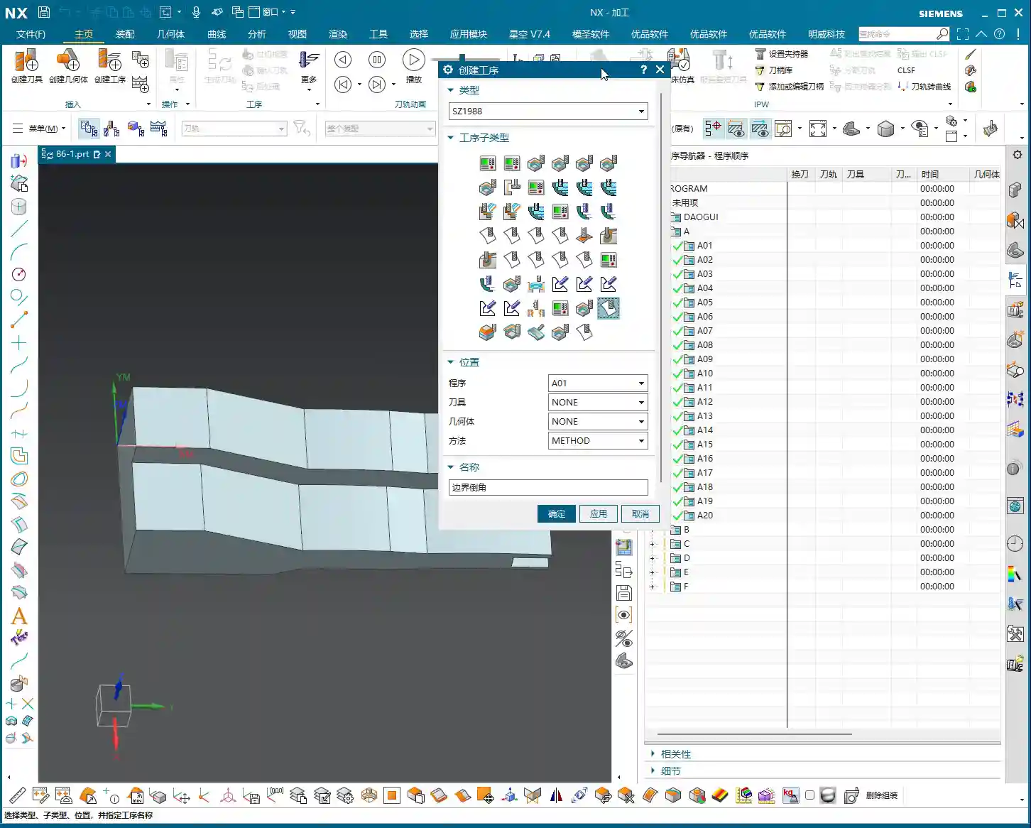
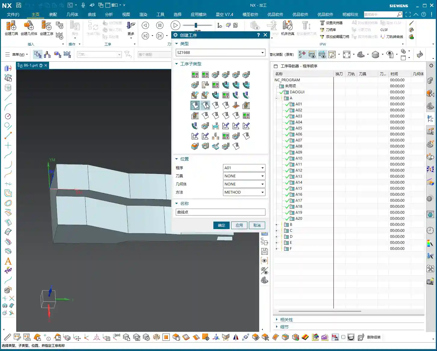
- Inserting the “Curve Point” Operation:
- In the Operation Navigator, right-click and select “Insert” -> “Operation.”
- In the dialog box that appears, select “Mill” for Type, “Multi-axis” for Method, then find the “Curve Point” command we’re learning today.
- Select the Workpiece and Tool (for now, the default Tool A will suffice), then click “OK.”
- Initial Look at the Operation Parameters Interface:
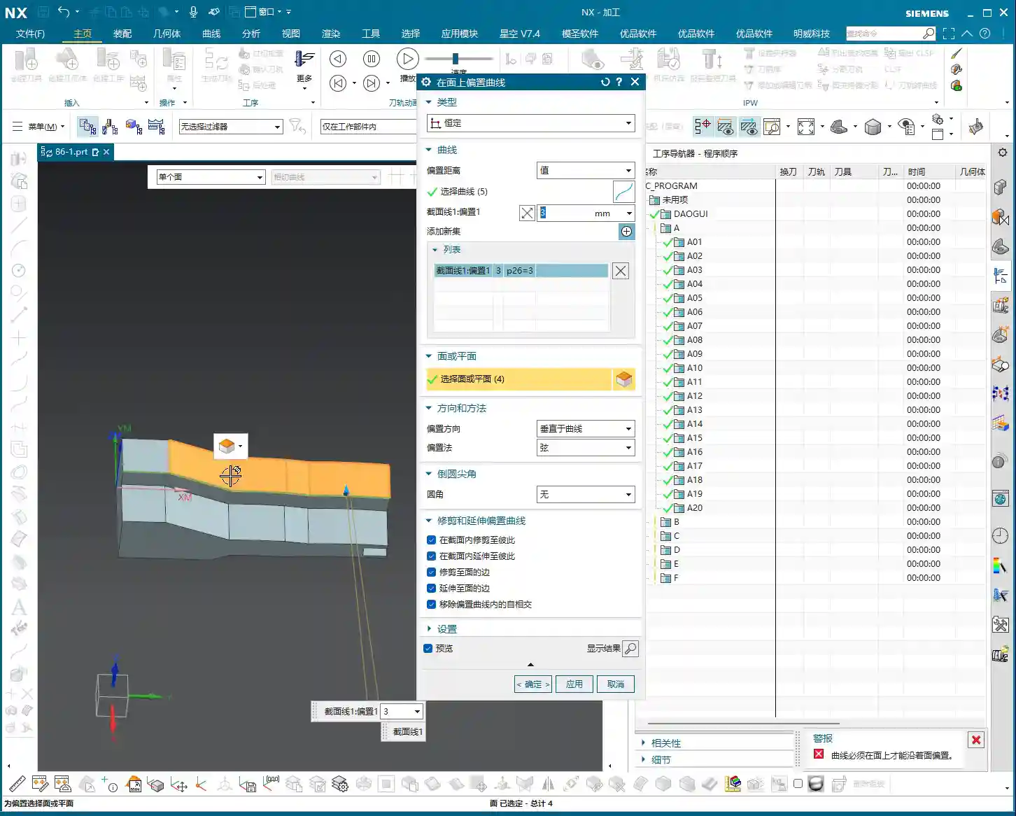
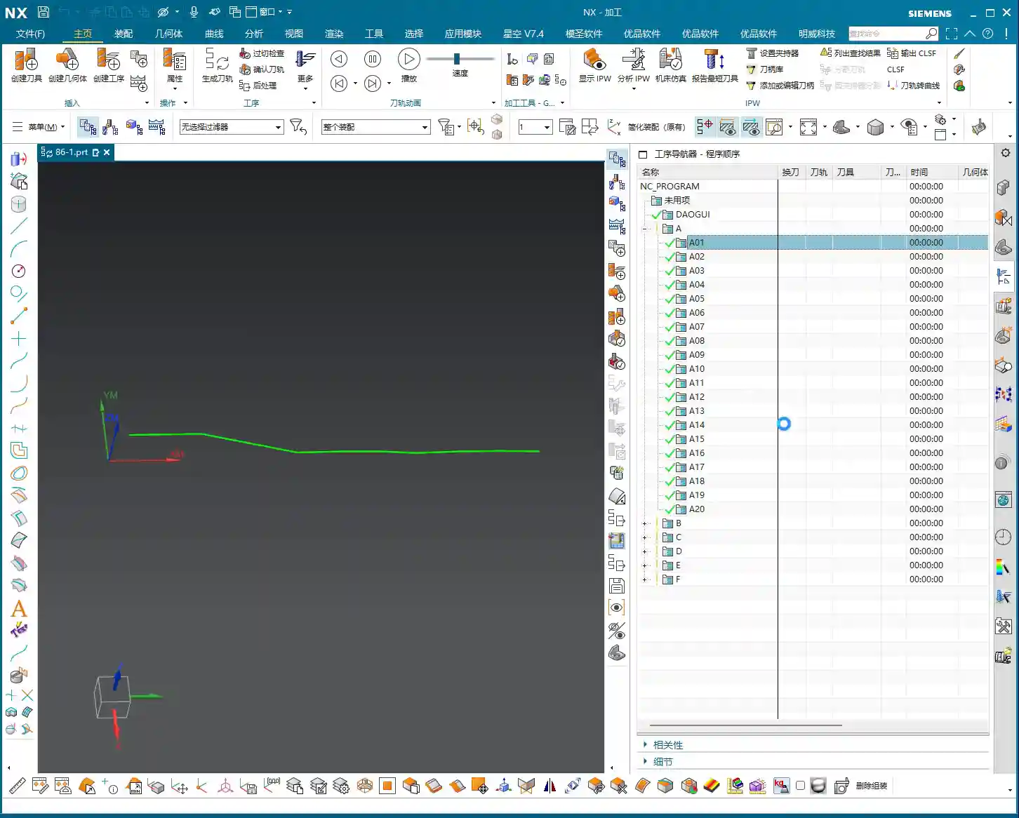
- Upon entering the “Curve Point” operation parameters interface, you’ll see many familiar options, such as Cut Part, Cut Area, Geometry, Tool, Tool Axis, and so on. Most of these are similar to operations we’ve covered previously, so don’t be concerned.
- The core here is how to select the “Curve Point” and subsequently define the Tool Contact Point and Tool Axis Vector based on this curve. We won’t delve into these details just yet, but keep in mind that these parameters determine your toolpath morphology and cutting performance.
- A Little Tip for Surface Analysis: In actual practice, when you get a new part, don’t rush into programming. Use Siemens NX’s analysis tools to check whether its surfaces are planar or freeform, and how their curvature changes. This helps you select the appropriate machining strategy and tool. For example, in the model I just demonstrated, some surfaces look flat, but upon analysis, they are actually micro-surfaces. Don’t underestimate these details; they directly impact your toolpath design and ultimate precision!

Summary: Pitfall Avoidance Guide
After all these years in the field, I’ve seen many junior engineers stumble in these areas. Master Wang offers you some warnings:
- Pitfall #1: Disregarding Fundamentals, Rushing for Quick Results. Commands like “Curve Point” are fundamental to Fixed Contour Milling, especially critical for multi-axis machining. Don’t treat earlier 2D and 3D tasks superficially just because they seem simple. A shaky foundation will cause everything to crumble; you’ll hit roadblocks everywhere as you progress. Even the lessons I covered previously, including those before lesson 86, must be mastered!
- Pitfall #2: Relying Solely on Software Simulation, Neglecting Actual Machining. The toolpath might look flawless in the software simulation, but once it hits the machine, you encounter issues like excessive tool engagement, tool chipping, or even a machine collision. Why? Because software simulations represent ideal conditions; they can’t accurately simulate the actual machine’s rigidity, tool wear, or material stresses. After programming, you absolutely must go to the workshop to observe the cutting sparks, listen to the tool sound, and monitor chip evacuation. That’s where real-world experience comes from!
- Pitfall #3: Neglecting Material Properties, Blindly Machining. Different materials (aluminum, titanium alloys, high-temperature nickel-based alloys) require vastly different cutting parameters, tool selection, and cooling methods. For instance, titanium alloys exhibit significant deformation after heat treatment and generate high cutting forces, demanding meticulous care during machining. Don’t expect one set of parameters to work for everything; that’s what an amateur would do.
- Pitfall #4: Overlooking Fixturing, Compromising Accuracy. When machining complex parts, a poorly designed fixturing setup will render even the best toolpath useless. Carefully consider cutting force direction, deformation, and chip evacuation space, fabricating custom fixtures when necessary. Oftentimes, accuracy issues aren’t the fault of the tool or the machine; it’s simply a matter of improper fixturing.
The Fixed Contour Milling command series in Siemens NX is the key to achieving high-precision, high-efficiency machining. Starting with “Curve Point,” subsequent lessons will become progressively more in-depth and engaging. Let’s work together to truly master these “hardcore techniques” that you won’t find in textbooks!
[EXCERPT]
Master Wang provides an in-depth explanation of Siemens NX Fixed Contour Milling’s “Curve Point” operation, emphasizing its core characteristic of “machining surfaces based on curves” as key to unlocking 3D and complex surface machining. He highlights the command’s critical importance for 4-axis/5-axis simultaneous programming, enabling refined toolpath control to meet high-precision machining demands. From a practical perspective, Master Wang guides users through an initial exploration of the Siemens NX interface and shares four “pitfall avoidance tips,” stressing the significance of real-world observation, material analysis, and fixturing design.

👤 About the Author:
The author is a veteran CNC machining professional with 15 years of industry experience, specializing in UG NX programming. This article is an original work representing personal practical insights.
⚠️ Copyright Notice: Unauthorized reproduction or distribution without prior communication is strictly prohibited.