📝 Key Takeaways: Master Wang provides a hands-on guide to applying Fixed Contour Milling with Curve Point in Siemens NX. From single-pass curve-following machining to multi-pass sidewall milling, he details stock control for sidewalls and bottom surfaces. He also reveals how to use “Transform Object” for toolpath patterning, efficiently tackling complex surfaces. This practical experience and pitfall avoidance guide will help you optimize your NX programming, boost machining efficiency and precision, moving beyond theoretical knowledge to address real-world production challenges.
Hello everyone, this is Master Wang. Today, we’re cutting straight to the chase – no fluff, just practical insights. In Siemens NX, there’s a “Fixed Contour Milling” operation, especially its “Curve Point” function. Many people think it’s simple, but those who truly master it can unlock its full potential, significantly boosting machining efficiency and precision. We’ll also cover “Multi-pass Toolpaths” and “Transform Object” together to clarify everything, ensuring you can immediately apply these techniques and avoid common missteps.
Curve Point Machining: The Maestro of Lines and Surfaces
Listen up. The “Curve Point” operation in Siemens NX, in a nutshell, means this: you select a curve or line, and the tool follows it to machine a surface. Whether that line is drawn, extracted from a model edge, or even an intersection curve between two faces, it will faithfully follow it. The biggest difference from other machining methods is that it doesn’t require you to select an entire region or boundary; it only recognizes the specific “line” you designate.
What is “Curve Point”? Simply put, it’s “Curve-Following Machining”
First, you need to select the part to be machined – that’s fundamental. Then, here’s the crucial part: you select the “curve” or “line” you want the tool to follow. Siemens NX will automatically calculate the toolpath, making the tool’s centerline or tool tip move along your chosen line while maintaining contact with the surface.
I’ll just pick a random part here and select an edge. See? The toolpath faithfully follows that edge. This is what we call “Guiding by Line, Machining the Surface.”

Stock Control: Sidewalls and Bottom Surfaces – Don’t Mix Them Up!
This is where problems often arise; many people get confused here. When we’re machining, especially during finishing passes, stock control is critical. In “Curve Point,” the method for setting sidewall stock and bottom surface stock is different.
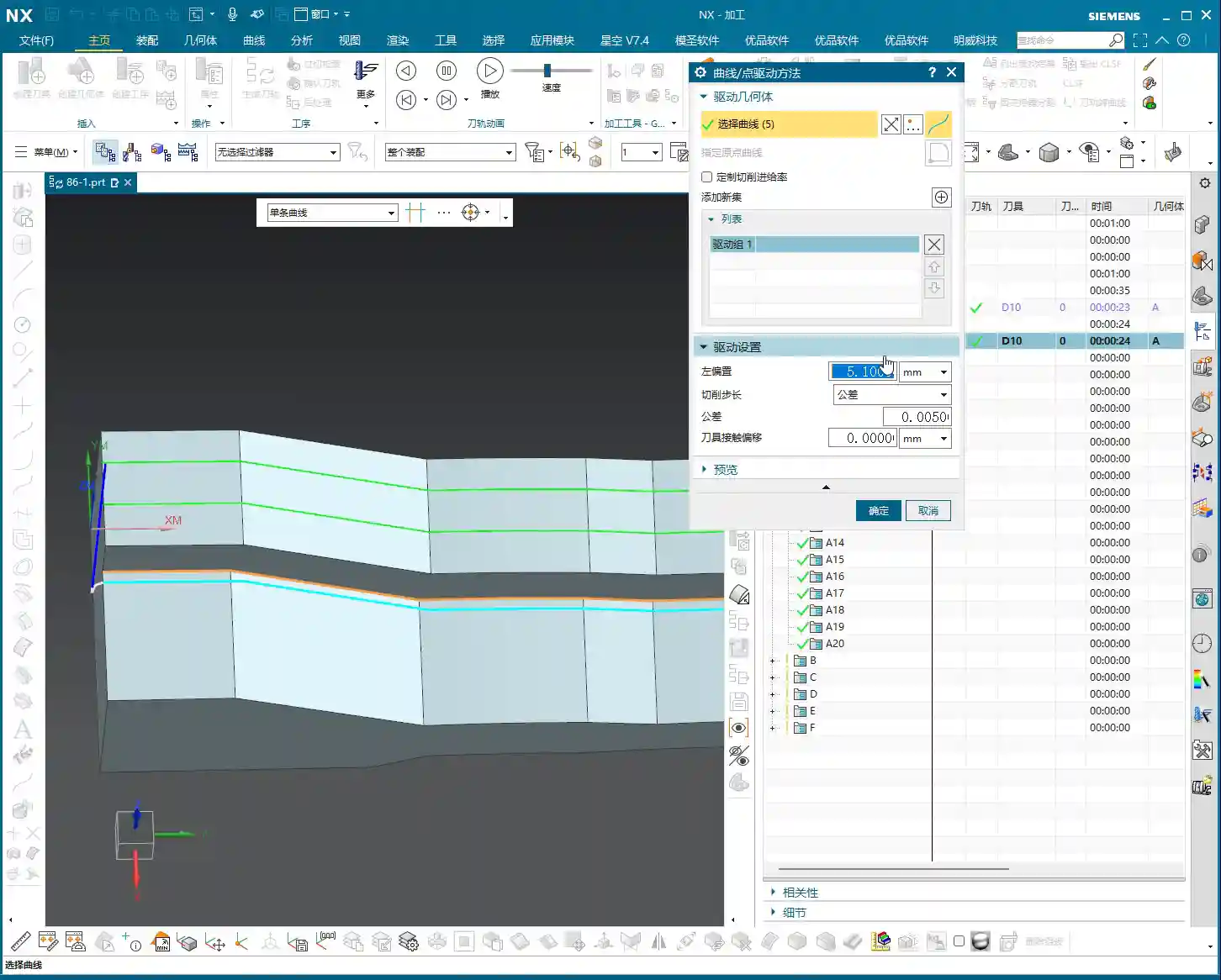
- Sidewall Stock (Offset): When the tool follows your selected line, you can make it offset outward or inward. For example, if I set an offset of 5 mm, the tool center will be 5 mm away from your chosen line. This offset value is the stock you’re leaving on the sidewall. Remember, this offset is specifically applied to your selected “line.”
- Bottom Surface Stock (Part Stock): If you want to leave stock on the entire bottom surface, you need to set it in the “Component” options. For example, I’ll set 0.1 mm (approx. 0.004 inch) of stock here. This means when the tool machines to its lowest point, it will leave 0.1 mm above the bottom surface. This is the overall stock for your selected “component.”
The stock in these two areas is controlled independently, so absolutely do not confuse them! One manages the side, the other manages the bottom. In practice, you’ll adjust them flexibly based on the workpiece and machining stage.
Single-Pass Toolpaths: A Powerful Tool for Specific Boundaries
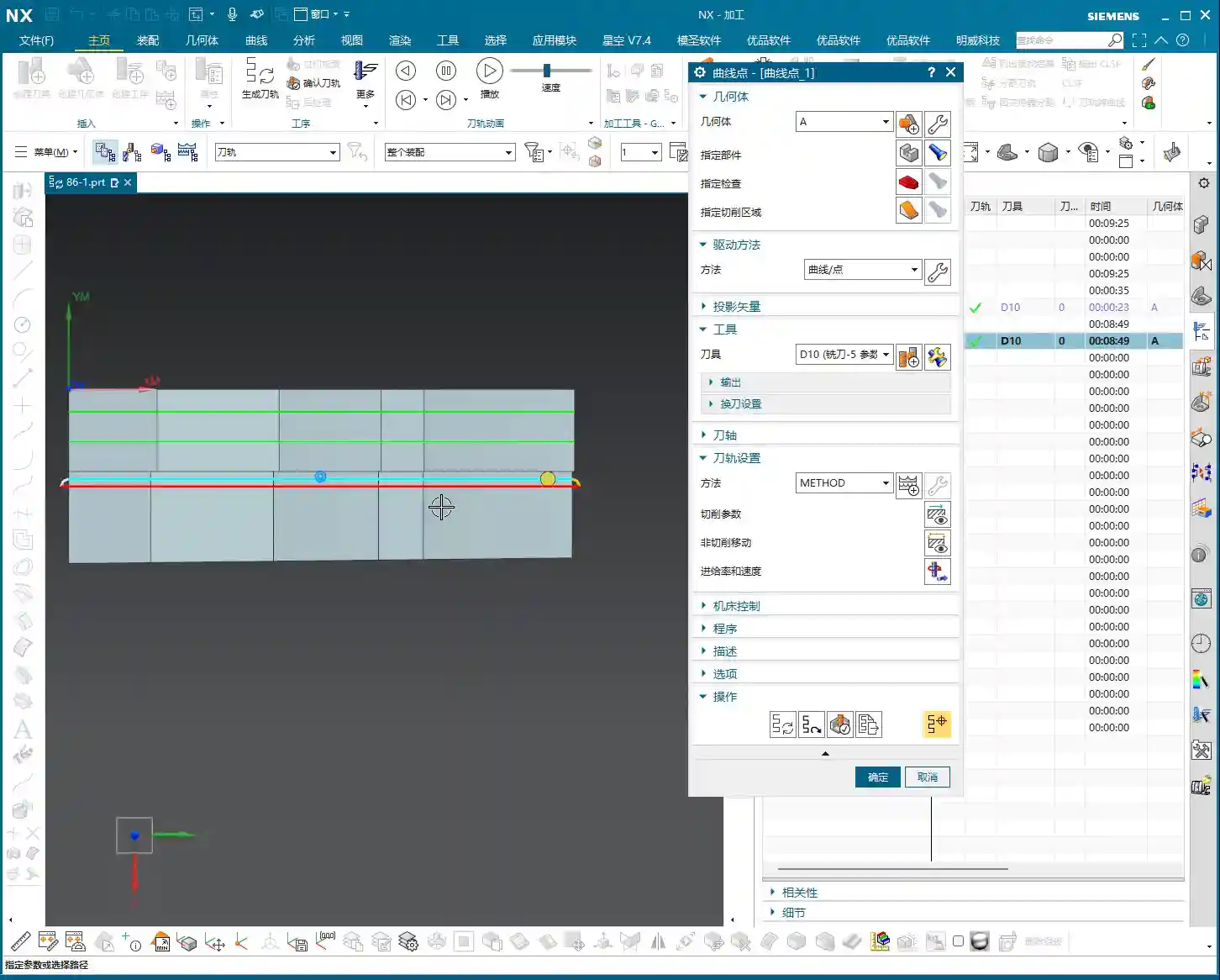
Many times, we need to run a single pass along a specific edge to clean it up or create a chamfer. Using “Curve Point” for this is incredibly convenient! You just need to select that edge, and a single toolpath is generated directly.
Think about it: if you used “Depth Contour Milling” or “Corner Cleanup” operations, you’d have to select boundaries, regions, and sometimes even define the bottom surface – what a hassle! “Curve Point” is simple and direct: just select the line, and a single pass gets the job done. Especially for models with small sudden protrusions, or edges that need a specific cleanup pass, this function is highly efficient.
Don’t underestimate this simple single pass; in actual production, it can save you significant time and improve local machining precision. Sometimes, simple is best.

Multi-pass Strategy: A Winning Move for Complex Sidewalls
A single pass is rarely enough. Often, we need to machine a sidewall or an inclined surface in multiple layers, with multiple passes. This is where “Curve Point” combined with “Multi-pass Toolpaths” becomes incredibly powerful. Especially for those complex, oddly shaped sidewalls that depth contour milling can’t handle, this combination can easily conquer them.
Activating Multi-pass Toolpaths: From “Solo” to “Group Attack”
In the parameter settings for “Fixed Contour Milling,” find and enable the “Multi-pass Toolpaths” option. Once activated, you can tell Siemens NX how many passes you want the tool to extend from your selected line in a specific direction, and what the stepover for each pass should be.
For instance, I’ve selected a line at the bottom of a sidewall and activated multi-pass toolpaths. I want it to move upwards and machine the entire sidewall. At this point, I can set the “Number of Passes” and “Stepover”.

Parameter Setting: The Art of Depth and Stepover
Let’s say this sidewall is 10 mm high. I want to machine it in 10 passes, with a Depth of Cut of 1 mm per pass. Then I can set:
- “Stepover” (or Depth of Cut/Stepdown in this context): I’ll set it to 1 mm (approx. 0.04 inch).
- “Number of Passes”: I’ll set it to 10 passes.
Siemens NX will then automatically offset the tool, pass by pass, along your selected line in the specified direction until all 10 passes are complete. This way, the entire 10 mm (approx. 0.4 inch) high sidewall can be machined in layers. This method is particularly effective for sidewalls with complex angles or freeform surface geometries. If you compare this with “Depth Contour Milling,” you’ll find that it often struggles to fully adapt to such irregular shapes. However, “Curve Point” combined with multi-pass toolpaths overcomes this issue because it follows your selected line, and that line can be any shape you desire.
Of course, tool retracts are unavoidable; the tool can only complete one pass in a single direction, then retract, and re-engage at the starting point of the next layer. This is both a characteristic and a manifestation of its flexibility. Don’t just rely on software simulations; observing the cutting sparks and chips in real life will show you that this method also ensures a more uniform tool load, extending tool life.
Transform Object: The Efficiency Secret for Batch Toolpath Duplication
The “Transform Object” function treats your toolpath like a “part” itself, allowing you to perform operations such as translation, rotation, mirroring, patterning (array), and more. When you need to repeatedly machine many similar features, or when different tools are required to machine the same area, it can significantly boost your programming efficiency. This function is an absolute game-changer, especially in mold making or aerospace component machining.

Exploring the Concept: Toolpath “Movement and Patterning”
You can think of “Transform Object” as a toolpath “patterning” or “copying” function. For example, if you’ve already generated a perfect single “Curve Point” toolpath, but you need to duplicate it several times to machine a wider flat or sidewall surface, that’s when “Transform Object” comes into play.
Within “Transform Object,” you can select various transformation types, such as “Translate,” “Rotate,” and so on. For what we just discussed—offsetting multiple toolpaths along a sidewall—”Translate” is typically used.
Translation Parameters: Y-axis Negative Offset Example
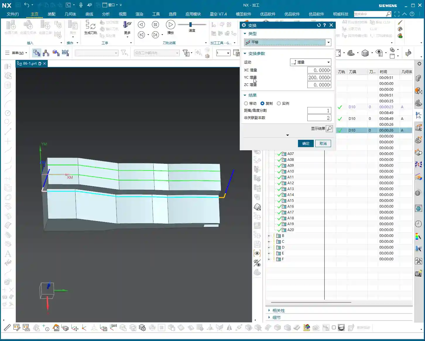
Suppose you already have a toolpath, and you want to translate it in the negative Y-axis direction, offsetting 8 mm (approx. 0.31 inch) each time, for 6 occurrences. You would set it up like this:
- Transformation Type: Select “Translate.”
- Direction: Select “Y-Axis.”
- Distance: Enter -8 (the negative sign indicates the negative Y-axis direction).
- Number: Enter 6.
Then confirm. Siemens NX will automatically generate 6 new toolpaths based on your existing one, each offset by 8 mm (approx. 0.31 inch) in the negative Y-axis direction. This way, you effortlessly obtain 7 parallel toolpaths (the original + 6 copied toolpaths), which can cover a wider machining area.
This method, combined with the flexible path generation of “Curve Point,” can double your efficiency when dealing with specialized surfaces (such as a wide inclined surface that isn’t a regular flat plane). You first use “Curve Point” to run a pass along an edge, then use “Transform Object” to duplicate that pass, covering the entire area. This is significantly faster than manually selecting lines and programming each pass individually!
Practical Application: Flexible Combination of Roughing and Semi-Finishing
In actual machining, you can even use “Transform Object” to combine roughing and semi-finishing. For example, you can perform a roughing pass with a large tool (D16), then use “Transform Object” to duplicate this toolpath. Afterward, modify the tool parameters to switch to a smaller tool (D10) for a semi-finishing pass. This approach results in a very clear process flow and extremely high programming efficiency.
Don’t underestimate these small tricks; on a production line where time is money, they can save you significant setup and programming time. These are the practical insights you won’t find in textbooks.
Summary: Pitfall Avoidance Guide
- Don’t Confuse Stock Settings: Remember, the sidewall offset in “Curve Point” is applied to the “line,” while the bottom stock is for the “component.” Set these independently. Don’t set sidewall stock within the component settings; that will lead to major issues, from scrapped parts to tool crashes!
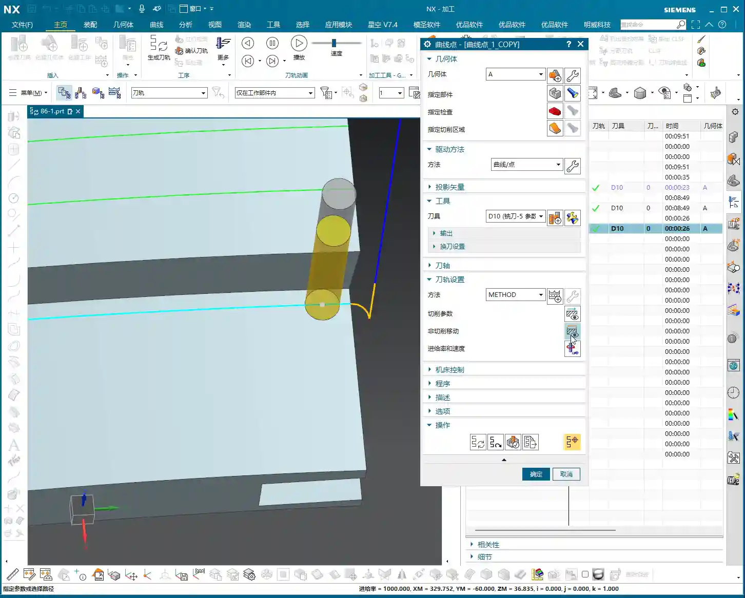
- Optimize Retracts and Air Cuts: While “Curve Point” combined with “Multi-pass Toolpaths” is flexible, it can sometimes generate unnecessary tool retracts and air cuts. You need to adjust the lead-in/lead-out methods based on the actual situation, for example, switching to “linear” lead-in/lead-out can significantly reduce superfluous motion. Don’t just rely on software simulations; observe the toolpath trajectory closely for optimization opportunities.
- Tool Selection Must Be Precise: For this “curve-following” machining method, tool selection is also critical. Especially when machining narrow areas, the tool radius must match the part’s fillets; otherwise, you risk incomplete cleanup or tool gouging. Grinding custom tools is also an art; when necessary, doing it yourself can be highly beneficial.
- Don’t Forget Material Properties: For different materials (aluminum, titanium, superalloys), cutting parameters, feed rates, and spindle speeds must all be adjusted. Don’t use a one-size-fits-all approach; that’s a recipe for disaster! Especially with titanium alloys and high-temperature nickel-based alloys, incorrect cutting parameters will lead to immediate tool failure.
- Fixturing is Fundamental: No matter how good your toolpath is, without stable clamping, it’s all for naught. Learn to design appropriate fixturing solutions and prevent heat treatment deformation; this is the first step to ensuring precision.
- Be Aware of Machine Error: Achieving ±0.005 mm (approx. ±0.0002 inch) precision isn’t solely about programming; you need to understand your machine’s inherent accuracy errors. Only by adjusting process compensation can you absorb these tiny deviations and bring the part’s precision back into spec.
Alright, that concludes today’s session. These are insights I’ve gained over many years, through hard work on the shop floor – not just theoretical stuff from textbooks. The more you ponder and practice, the more skilled you’ll become. Next time you encounter any tricky problems, we’ll talk!
👤 About the Author:
The author is a veteran CNC machining professional with 15 years of industry experience, specializing in UG NX programming. This article is an original work representing personal practical insights.
⚠️ Copyright Notice: Unauthorized reproduction or distribution without prior communication is strictly prohibited.