📝 Key Takeaways: **
Siemens NX Roughing Optimization: Say Goodbye to Excessive Retracts
Hello everyone, I’m Master Wang. Today, let’s continue our chat about…
[VIDEO_HERE]
Hello everyone, I’m Master Wang. Today, let’s continue our chat about machining, especially **roughing**. It might look straightforward, but there are plenty of hidden tricks, particularly those “details you won’t learn from textbooks” that significantly impact efficiency and cost.
Mastering Key Roughing Challenges
No Allowance? Beware the First Cut!
Listen up. When setting up a **roughing** program in NX, some tend to think “good enough.” Especially when specifying the part and blank, a common mistake is to leave too little stock allowance, or none at all. For today’s part, when designating components, don’t treat every face as the final finished surface. For load-bearing areas like the bottom face, don’t leave too much allowance—0.01mm (approx. 0.0004 inch) is plenty, just enough for a single cutting pass. Why? Because if you leave no allowance, or the wrong amount, the machine will struggle on the first **Depth of Cut (DOC)** due to insufficient cutting space, or it might crash directly into the bottom. That’s a serious problem! Don’t just trust the software simulation; the sparks from the actual machine cutting will tell you the truth.
Small Areas “Overcut”? Cleverly “Avoid” Them with Sheet Bodies
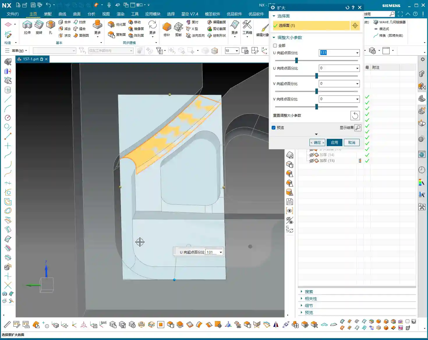
When machining complex parts, there are always some small, tricky areas that are hardly worth machining; they just waste tool life and time. Take this part, for instance: once the program runs, you’ll see some of these small areas are machined unnecessarily. Why bother? In reality, these spots can be entirely skipped.

My trick is: find a Sheet Body and “block” it off. For example, using Siemens NX’s “Extend Face” command, you can stretch a face outwards to create a “virtual barrier.” Then, during programming, include this “virtual barrier” in your selection and tell the software: “Don’t machine this area; go around it!” This way, the toolpath will automatically avoid these unnecessary regions, saving a good amount of machining time. Don’t underestimate a few minutes; in mass production, that adds up to serious money!
Optimizing Retracts: Two Practical Strategies
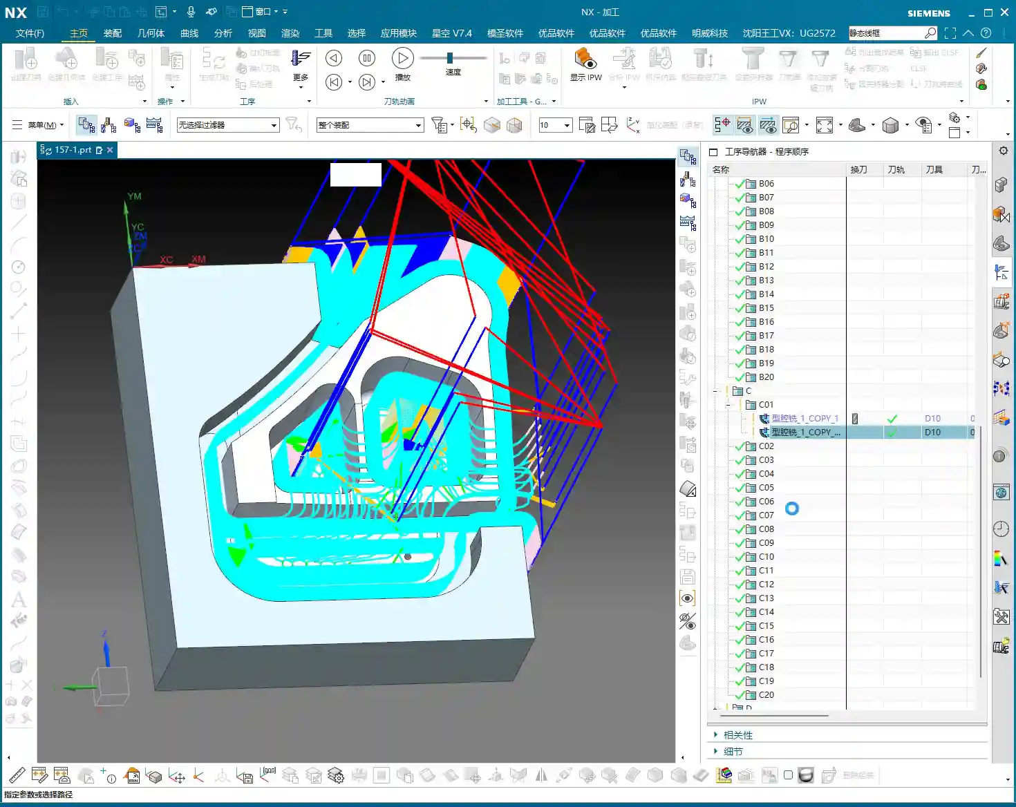
We just generated a program. Now, take a closer look at the toolpath. Do you notice the tool “jumping” too high between different areas? When retracts are high, there’s more air-cutting, and all that time is wasted on tool lifting. We need to figure out how to control these retracts. Here are two practical strategies I’ll teach you.

Strategy One: Layered Control, Clever Use of Empty Layers
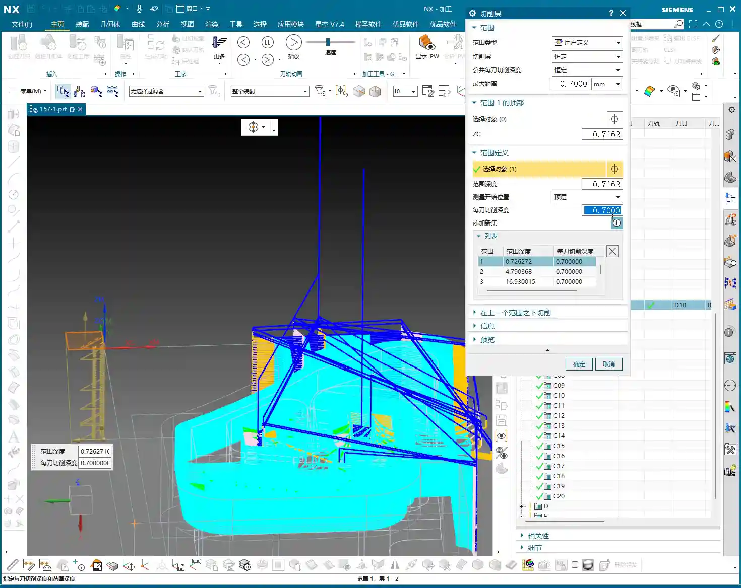
In Siemens NX’s “Cut Levels” settings, many simply use automatic or define a few basic levels. But to finely control retracts, we need to get a bit more creative.
1. **Add an “Empty Layer” as a Buffer:** First, create an “Empty/Clearance Layer” at the top. This layer doesn’t participate in actual cutting, but it defines the tool’s initial retract height. Slightly raise the height of this empty layer, for example, to about 0.7mm (approx. 0.027 inch) above the workpiece surface. This 0.7mm isn’t arbitrary; it must ensure the tool can move smoothly after retracting without lifting too high and wasting time. If you set it to 0, the tool might move directly along the surface, risking rubbing or even a crash!
2. **Define Cutting Regions:** Next, add another layer, defining it to the top surface of the workpiece as the actual cutting start point. Then, define the bottom surface as the cutting endpoint. This way, when the tool moves between each **Cut Level**, it won’t always retract to a high **Clearance Plane**; instead, it will rapidly transfer at the height set by this “Empty Layer,” significantly reducing air-cutting time.
This method can be a bit tedious and requires repeated trial and error, but once set correctly, the results are immediate.

Strategy Two: Rapid Transfer with a Clearance Plane
If controlling retracts via **Cut Levels** feels too intricate and easy to get bogged down in, then the second method is much simpler and more direct, yet equally effective—sometimes even more practical.
Instead of using complex **Cut Levels**, simply duplicate your **roughing** program and then locate the “Transfer Rapid” option. Here, you can set a “Relative Plane.”
For example, directly set a **Clearance Plane** at 100mm (approx. 3.94 inch) high. This means that after each cutting operation, the tool will rapidly retract to this relative plane, then perform rapid moves along that plane before descending to the next cutting position. While the retract height is fixed each time, as long as this height is set appropriately and doesn’t interfere with the **fixturing**, it can still effectively reduce air-cutting and ensure safety.

Both methods have their pros and cons, but they both achieve the same goal: making the tool “retract less and move faster.” In practice, you can choose based on the workpiece complexity and your personal preference.
Master Wang’s Machining Philosophy
Don’t Just Look at Parameters, Consider the Fixturing!
When we input parameters and set planes in NX, there’s a crucial prerequisite: you must have the workpiece’s actual clamping setup in mind! Just like when we set that 3mm (approx. 0.118 inch) plane, or the 100mm (approx. 3.94 inch) **Clearance Plane**, you need to ask yourself: “If the tool retracts this high, will it collide with the **fixturing**?” Especially clamping plates (Clamping Interference) – that’s a very real risk. Don’t just focus on how beautiful the toolpath looks; safety in production is paramount. In the factory, a wrong parameter might scrap a part, but a tool crash can cause a major accident!
Roughing Done, Straight to Finishing Pass
Today’s **roughing** operation might have taken some effort, but the final result is good. See, the toolpath is smooth, retracts are optimized, and it’s basically where it needs to be. So, in situations like this, we can skip the semi-**roughing** and go straight to a finishing pass. Choose a suitable D10 tool (10mm diameter end mill). For the machining direction, you can select “Outward” milling; this ensures better chip evacuation and a more guaranteed surface finish. Of course, sometimes “Inward” milling is also an option; this all depends on the specific part geometry and cutting conditions. Practice more, observe the cutting sparks and sounds, and you’ll understand.
Summary: Pitfall Avoidance Guide
* **Ensure Ample Stock Allowance, Secure the First Cut**: For initial cuts or critical surfaces, leave an allowance of about 0.01mm (approx. 0.0004 inch) to ensure a smooth engagement.
* **Cleverly Use Sheet Bodies to “Block” Areas**: For non-critical, small regions, use commands like “Extend Face” to create virtual sheet bodies to “obstruct” them, reducing unnecessary cutting.
* **Optimizing Retracts is Key**:
* **Layered Strategy**: In **Cut Levels**, set an “Empty Layer” as a low **Clearance Plane** height (e.g., 0.7mm (approx. 0.027 inch)) to control rapid tool transfers.
* **Plane Strategy**: Use “Transfer Rapid” to set a “Relative Plane” (e.g., 100mm (approx. 3.94 inch)) as a unified tool retract and movement plane.
* **Always Consider Fixturing**: Any Z-axis setting must account for **fixturing** interference to ensure machining safety.
* **Flexible Toolpath Decision-Making**: When **roughing** is optimized, skip semi-**roughing** and choose either inward or outward **finishing pass** methods based on the situation.
Alright, that’s all for today. These are insights I’ve meticulously developed over 15 years on the shop floor. I hope you’ll take them to heart, practice more, think more, and don’t just stare at the NX interface—look up and observe the actual machine and parts. That’s where the real skill lies!
👤 About the Author:
The author is a veteran CNC machining professional with 15 years of industry experience, specializing in UG NX programming. This article is an original work representing personal practical insights.
⚠️ Copyright Notice: Unauthorized reproduction or distribution without prior communication is strictly prohibited.