Tag: Finishing

  • Multi-Process Complex Part Finishing: Master Wang, an NX Expert, Guides You Step-by-Step from Roughi

    📝 Key Takeaways:

    Practical Finishing of Multi-Process Parts

    Hello everyone, I’m Old Wang, Engineer Wang. Today, let’s continue our discussion on machining…

    [VIDEO_HERE]

    Hello everyone, I’m Old Wang, Engineer Wang. Today, let’s continue our discussion on machining multi-process parts. Listen up, this isn’t a job you can do with your eyes closed; it’s all about experience and attention to detail. Let’s start from the beginning and talk about machining the front face (Face A).

    Roughing Strategy and Tool Path Optimization for the First Face

    Fixturing and Workpiece Positioning

    First, workpiece clamping. For roughing the front face (Face A), we’ll start by securing the raw material firmly with a vise. Why? Because roughing involves high cutting forces, and poor rigidity can easily lead to chatter, or even tool ejection, which would cause serious trouble. Positioning must be precise, and datums must be clear; this is the foundation for all subsequent precision machining.

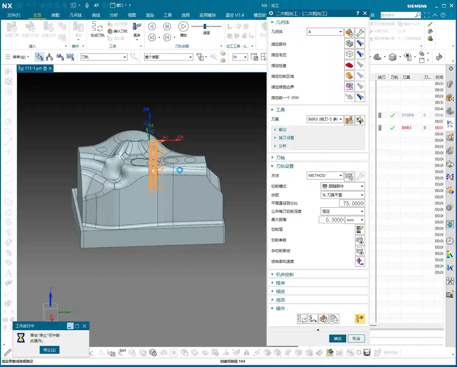
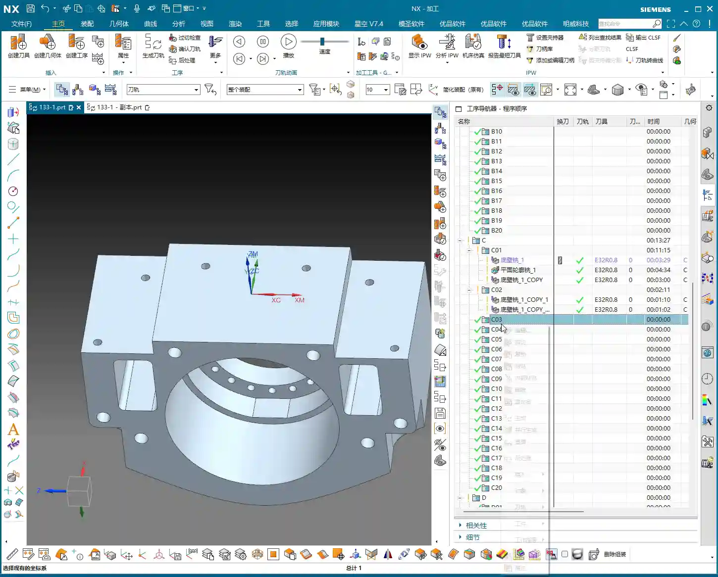
    Roughing Tool Selection and Feed Strategy

    I just repositioned the tool start point; I accidentally clicked the wrong location earlier. We’ll continue roughing with a large-diameter flat-bottom tool with a corner radius (either a ball nose end mill or a corner radius end mill). For instance, here, we’ll choose a Φ32mm (approx. 1.26 inch), R0.8mm (approx. 0.03 inch) corn end mill, or a large face mill with a corner radius. This type of tool balances cutting efficiency and strength. The corner radius effectively distributes cutting stresses, extends tool life, and reduces stress concentration at sharp corners. For the tool path, the Depth of Cut (DOC) is set to 2mm (approx. 0.08 inch). However, we’ll initially leave a bottom stock of 0.8mm (approx. 0.03 inch), and some on the sides as well. This is to provide sufficient material for finishing, preventing the finishing tool from taking heavy impacts directly.

    For the tool path, we’ll start with a Zig-zag pattern to quickly remove most of the material. If the tool path doesn’t feel ideal—for example, too many air cuts or unstable machining—we need to adjust it. Siemens NX offers many strategies. Don’t just rely on software simulation; consider whether the cutting sparks on the actual machine are consistent and if the sound is smooth. No matter how advanced the software, it can’t fully replace the ears and eyes of an experienced machinist.

    Tool Path Optimization to Avoid Excessive Tool Engagement

    As mentioned, if the tool path strategy isn’t ideal, we need to adjust it. For example, switching from a Zig-zag pattern to an Offset pattern. The offset pattern provides more uniform tool engagement along the contour edges, preventing the tool from engaging too deeply in corners, which can lead to chipping or workpiece deformation. Especially when machining near edges, if a zig-zag pattern tends to cause overcutting or vibration, an offset pattern offers better control over cutting forces. We’ll set the Stepover to 85% of the tool diameter. This ensures both efficiency and sufficient material allowance for the finishing pass.

    After machining, check the part. We’re left with a bottom stock of 0.15mm (approx. 0.006 inch), which is an acceptable size, making it convenient for the subsequent single-pass finishing operation.

    Finishing and Detail Processing for the First Face

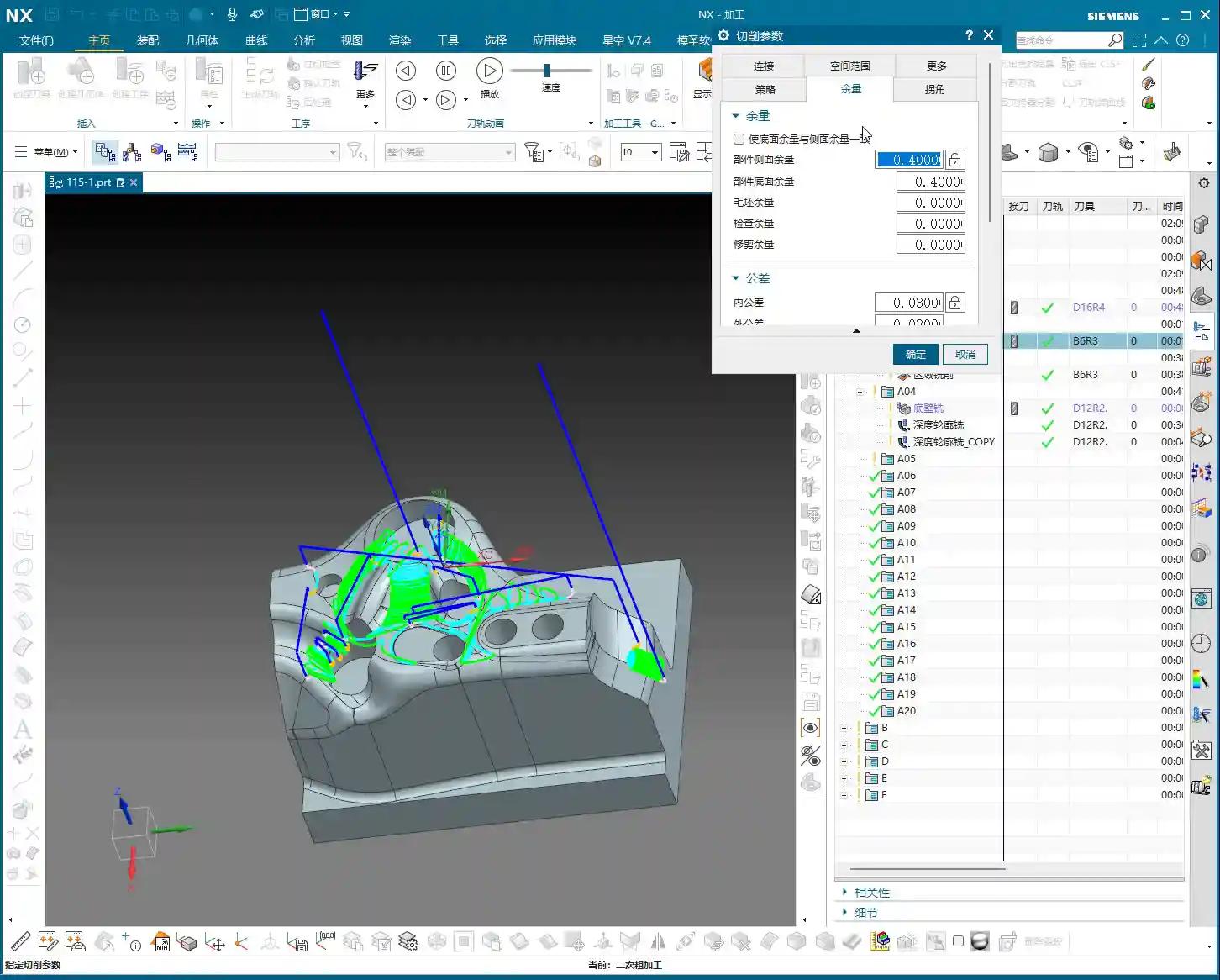
    Finishing Stock Control

    Once roughing is complete, it’s time for finishing. As usual, copy the roughing program and then modify the parameters. Finishing stock must be strictly controlled, with all allowances set to 0. However, pay attention: some side walls require a separate finishing pass with a smaller tool. Therefore, we can temporarily leave 0.25mm (approx. 0.01 inch) on the side walls. Don’t remove everything in one go; that can easily lead to “tool deviation” or failure to meet surface finish requirements.

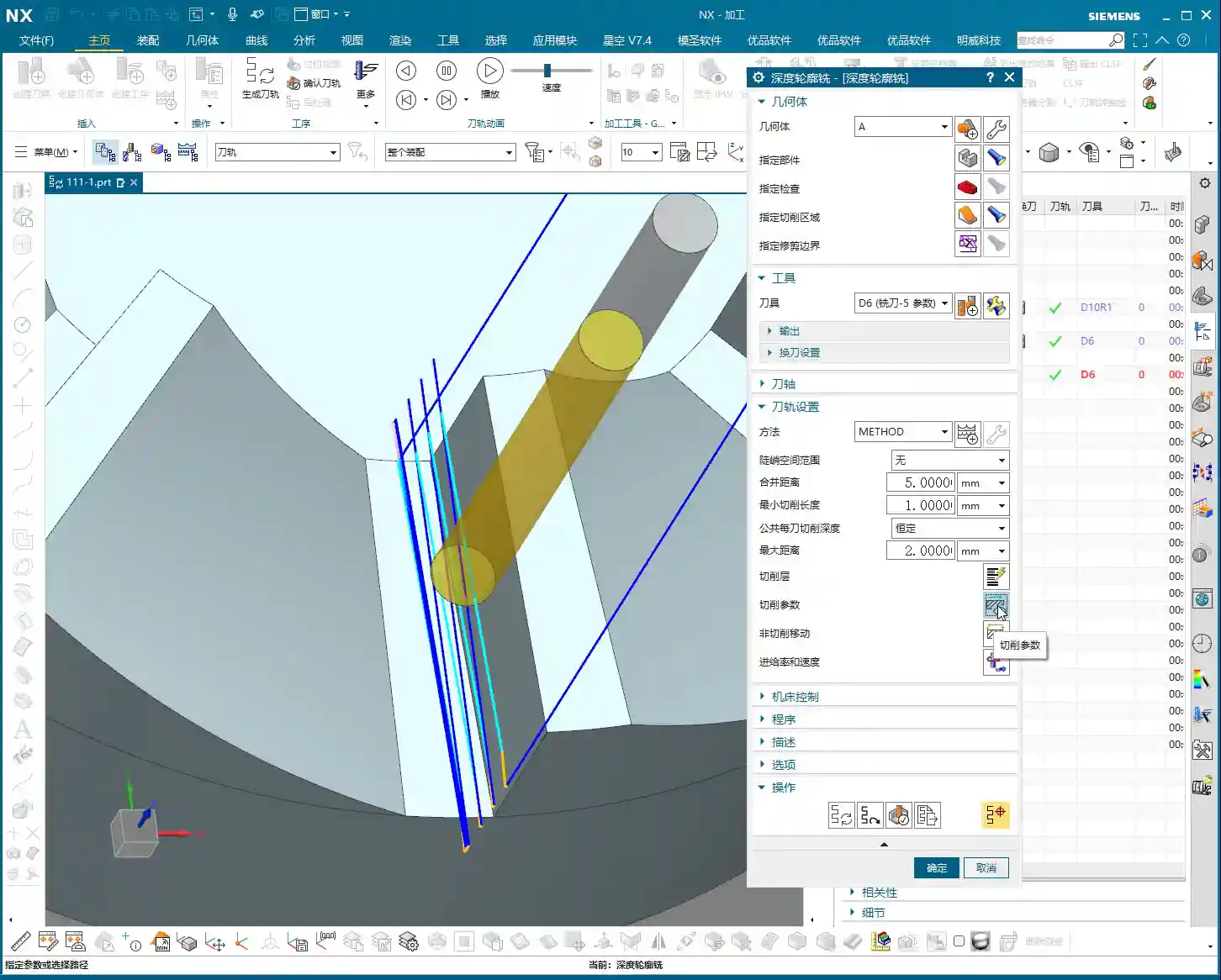
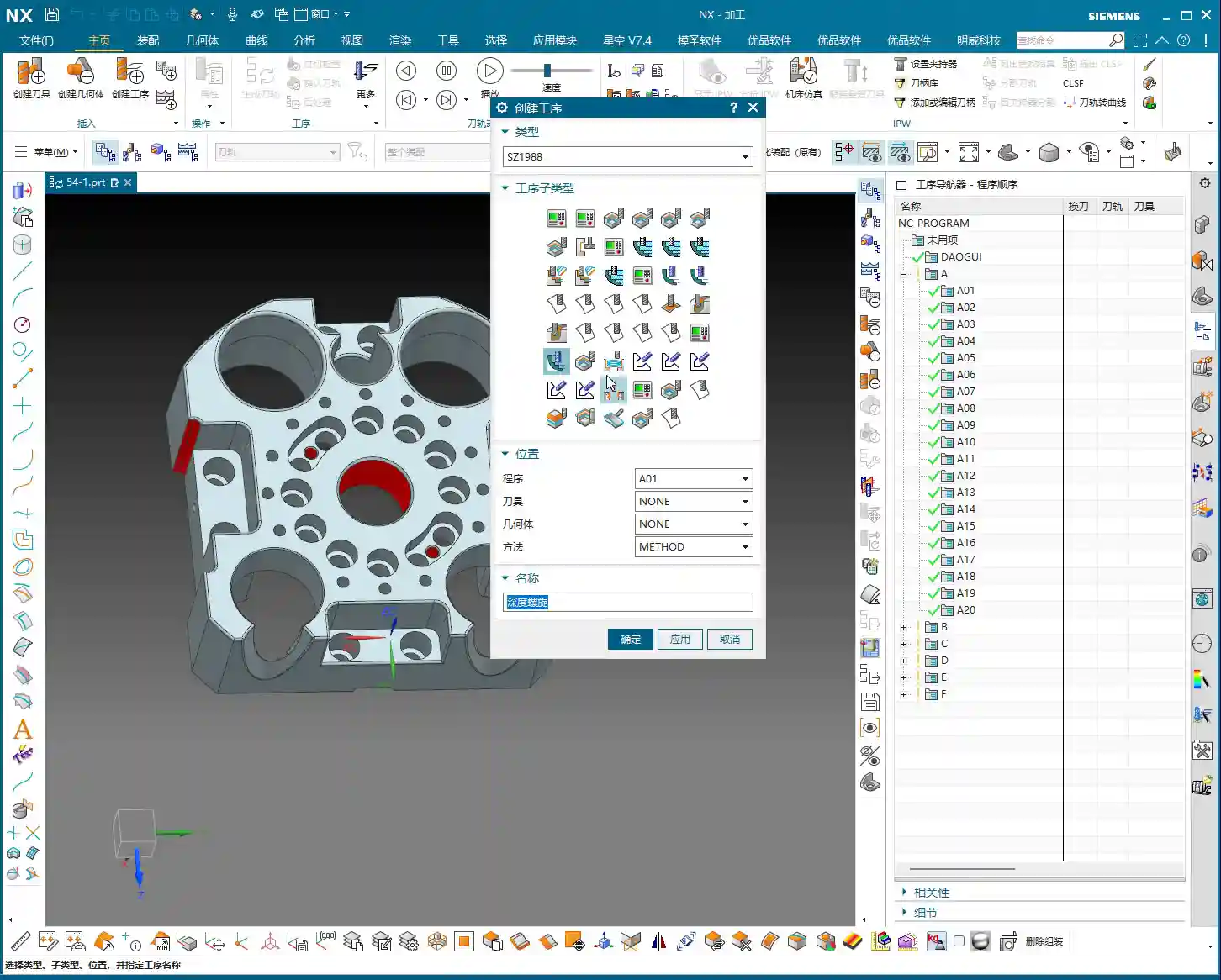
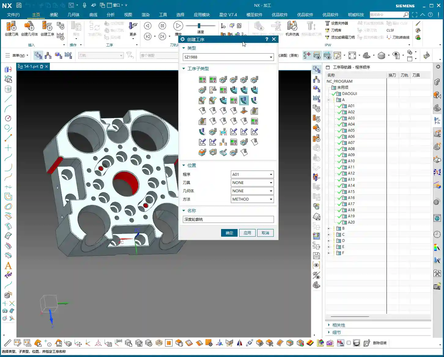
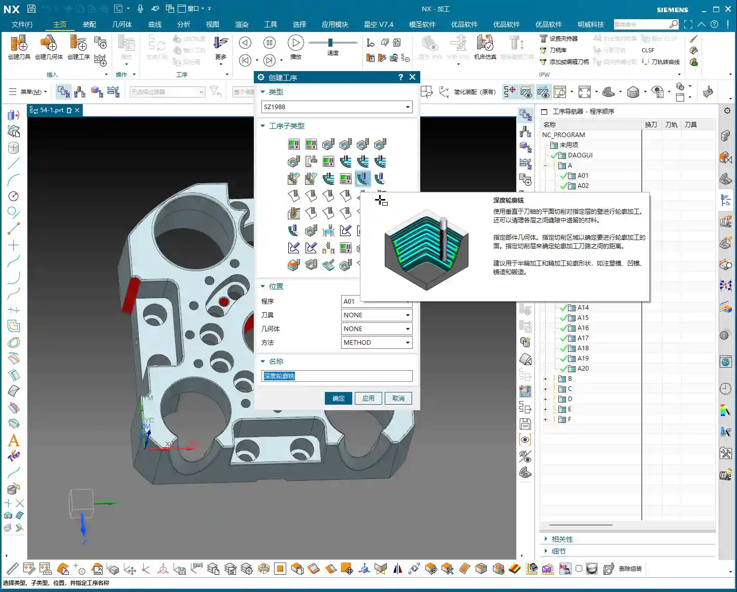
    Planar Contour Milling and Boundary Control

    In Siemens NX, for finishing flats and contours, the “Planar Mill” or “Contour Mill” strategies are commonly used. If the workpiece contour is complex or has open boundaries, we cannot simply use a zig-zag pattern. We must use Planar Contour Milling and properly define the cutting region (face or curve) and boundary type (open or closed). For example, here, we’ll set the cutting direction for one open area to “Right” and another to “Left”, ensuring the tool path covers the entire area without cutting into unintended regions.

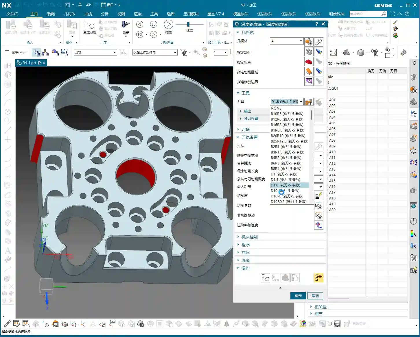
    We’ll still use the Φ32mm (approx. 1.26 inch), R0.8mm (approx. 0.03 inch) tool. Set the Depth of Cut (DOC) and stock allowance to 0, which means a single pass to the final depth, finishing the bottom face. This completes the large-area finishing.

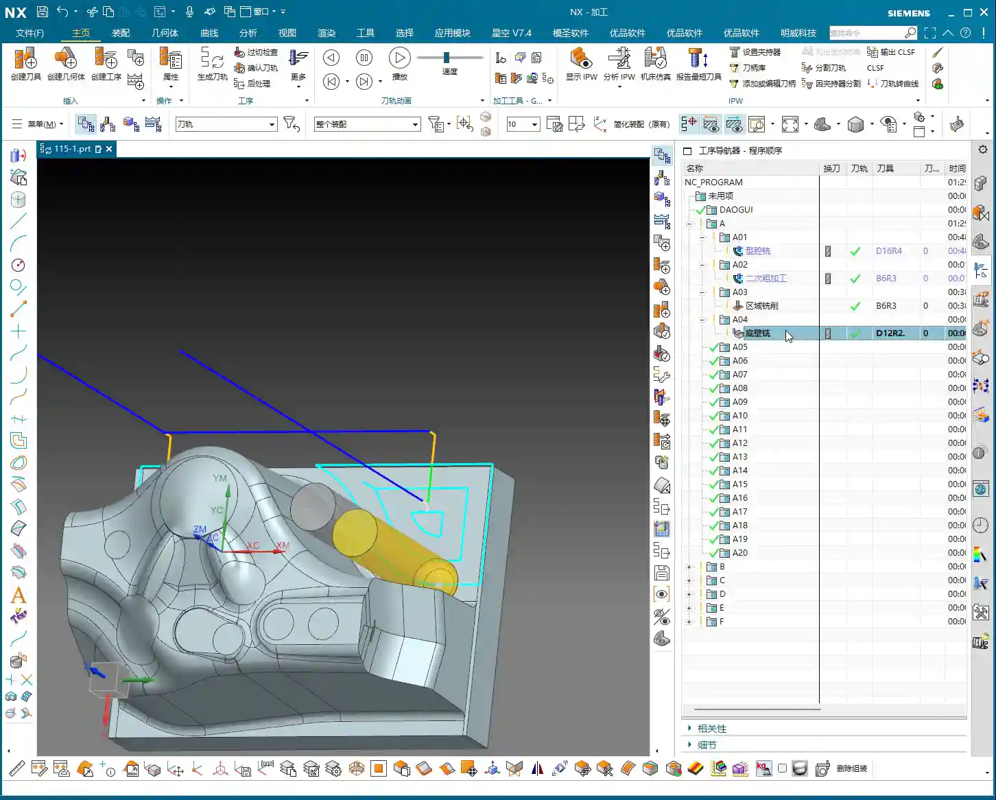
    Side Wall Finishing and Dedicated Tools

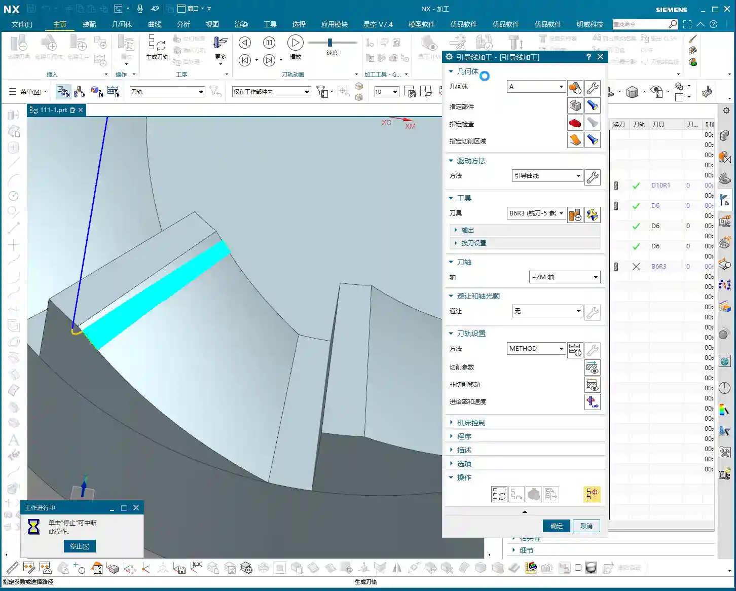
    The side walls we mentioned earlier still have 0.25mm (approx. 0.01 inch) of stock remaining; now it’s their turn. These side walls typically require a better surface finish or smaller radii. We’ll need to switch to a small-diameter flat end mill, such as a Φ10mm (approx. 0.39 inch) flat tool, or even a smaller one for the finish cut. Set the stock allowance to 0, and change the cutting method to “Along Boundary” or “Follow Profile”. With a single pass, machine the side wall cleanly. This ensures both surface finish and perpendicularity. Don’t underestimate this 0.25mm allowance; it’s your margin for error, preventing large steps or damage from occurring during roughing with a larger tool.

    When finishing side walls, pay attention to the tool stick-out length. If the tool protrudes too far, it can easily lead to chatter, affecting surface finish, or even cause tool breakage. Therefore, keep it as short as possible. Here, my tool stick-out is a bit long, but for demonstration purposes, we’ll proceed as is. In actual machining, I would try to shorten the stick-out length as much as possible or opt for a reinforced tool holder.

    Hole Machining: Preparation Before Drilling and Tapping

    Hole Recognition and Optimized Drilling Sequence

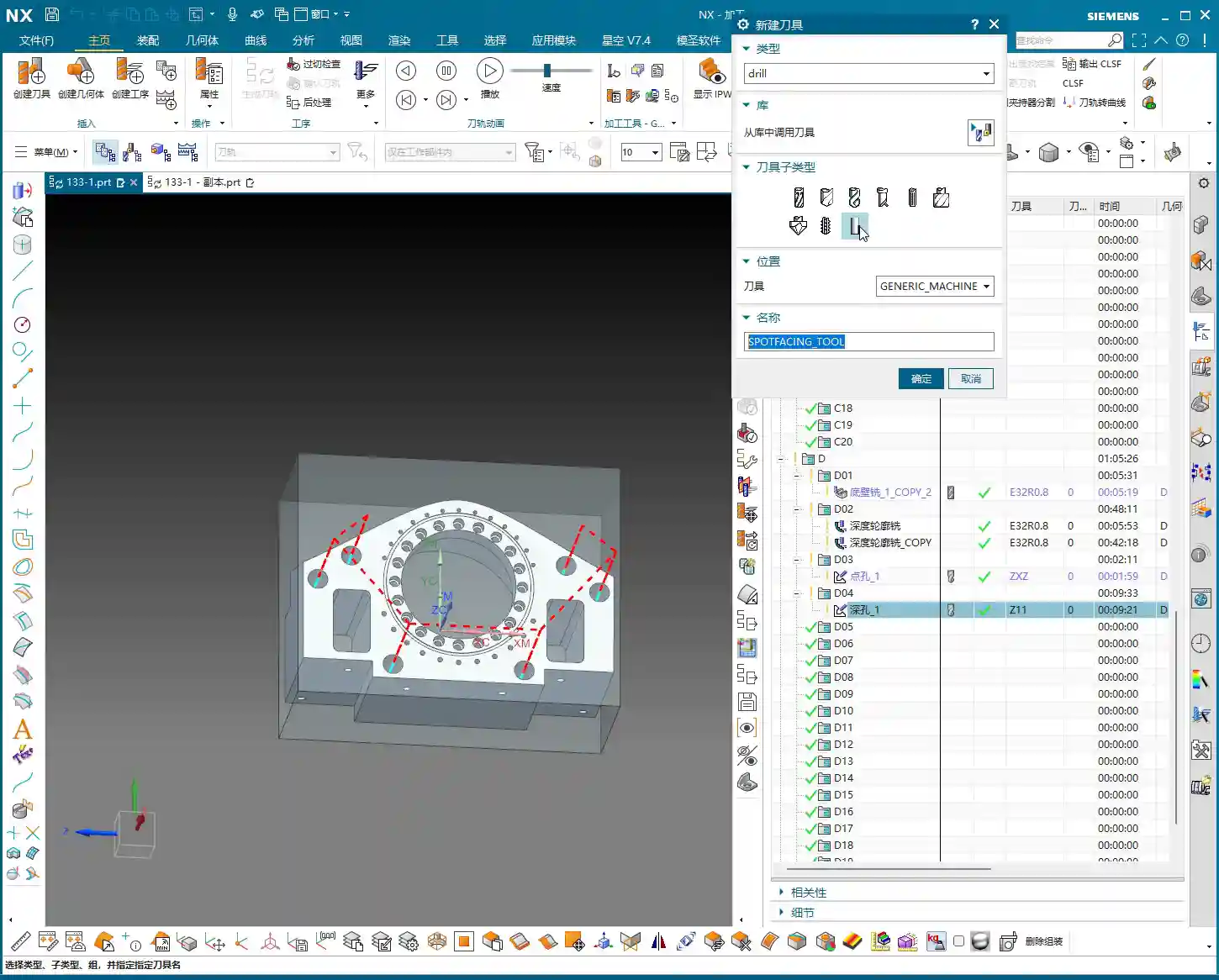
    After machining the faces, next come the holes. Hole machining cannot be careless, especially when high dimensional accuracy is required. Siemens NX’s “Hole Machining” module is very powerful and can automatically recognize all holes. What we need to do is optimize the drilling sequence to minimize air cuts. Drill smaller holes first, then larger ones, or go from inside to outside, or high to low. This avoids multiple tool changes and unproductive movements, saving time and thus cost!

    First, use a center drill (or spot drill) to spot the holes for positioning and to prevent the drill bit from wandering. Then, use a twist drill for drilling the holes. Here, we’ll select a center drill to spot the hole locations.

    “Drawing is King” Principle for Drilling Depth and Dimensions

    After spot drilling, proceed with drilling. Here, I checked the hole diameter and found it to be 6.8mm (approx. 0.268 inch). This is clearly the pilot hole for an M8 thread. This means that after drilling this hole, an M8 thread will need to be tapped. The hole depth is absolutely subject to the “drawing is king” principle! Some holes are through holes, others are blind holes, and their depths vary. Never rely on intuition; always carefully cross-reference the drawing for each hole’s depth and requirements. If the drawing specifies a flat bottom for a blind hole, then a flat-bottom drill must be used for machining.

    For demonstration, I’ll set a random depth for now. But during actual operations, better slow than wrong! Especially before tapping, the pilot hole’s size and depth are critical. If the pilot hole is too small, tapping can easily break the tap; if it’s too large, the thread strength will be insufficient. These are lessons learned the hard way.

    Here, we’re just outlining how to program it. But for actual machine operation, you must be even more diligent, striving for perfection, especially regarding depth and tool life.

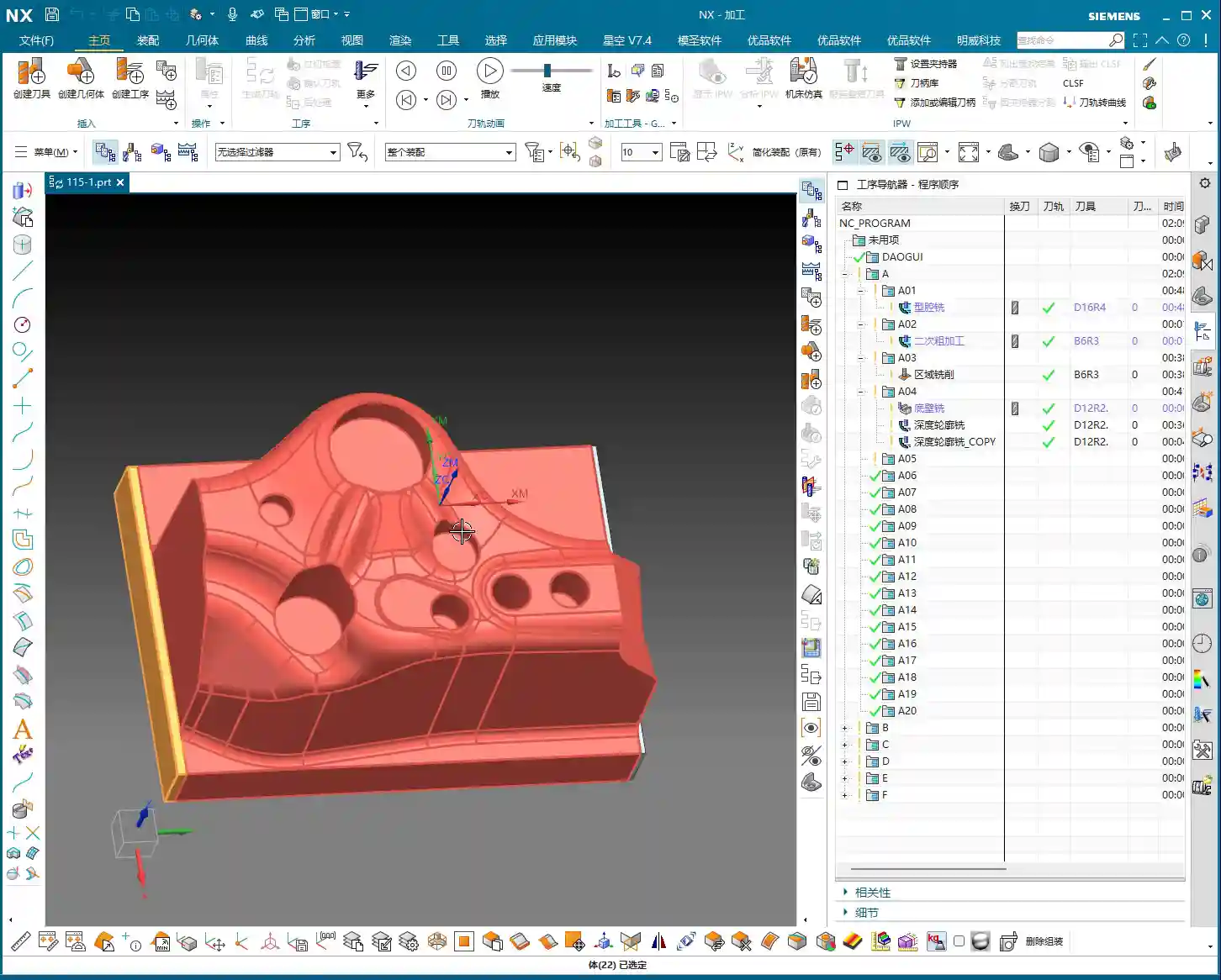
    Flip Machining: Establishing and Inheriting the Second Face Datum

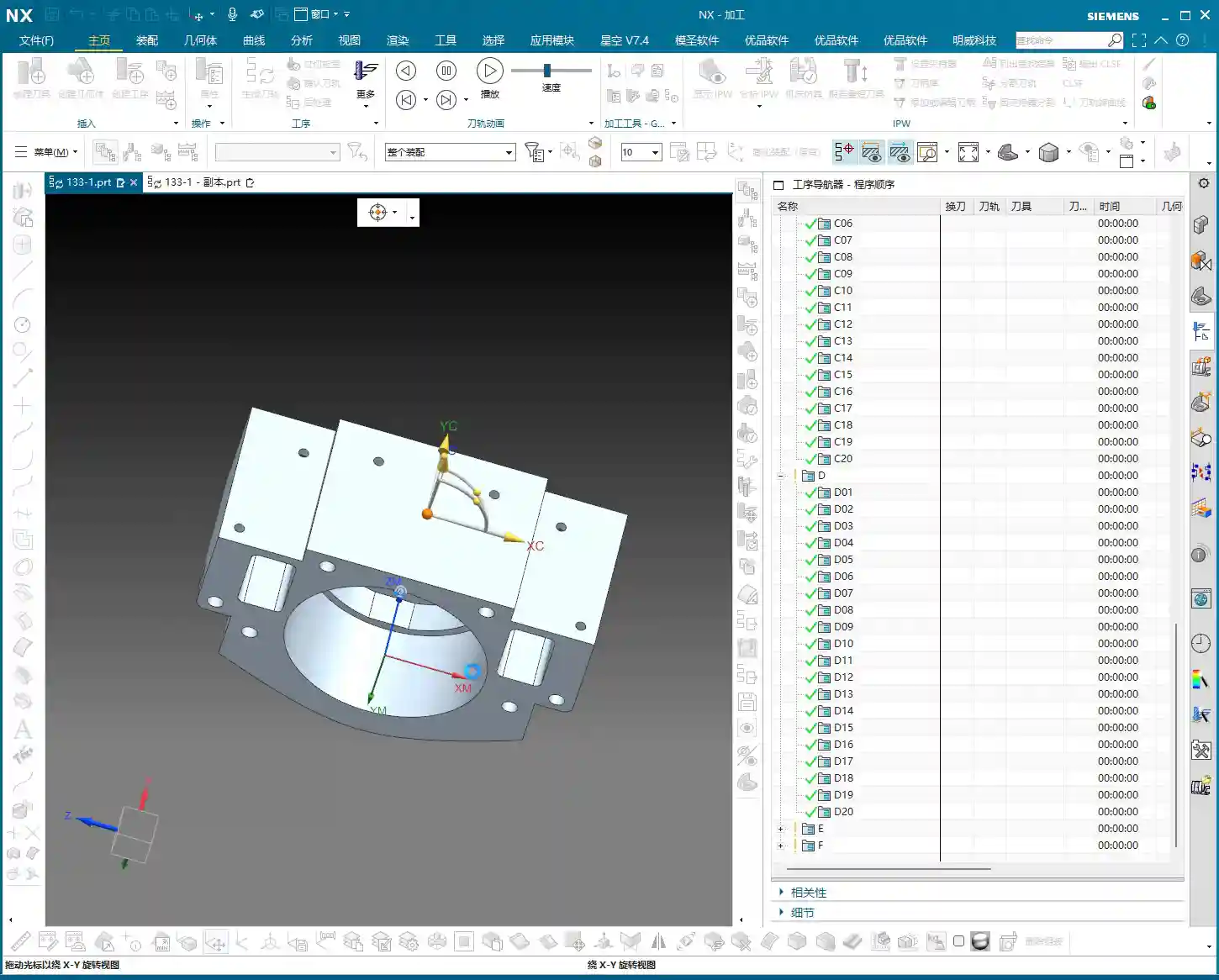
    Datum Face Selection and Workpiece Preparation

    With the front face machined, it’s time to flip the part and machine the back face (Face D). The most critical aspect of flip machining is the establishment and inheritance of datums. We typically choose a previously machined, high-accuracy face as the secondary datum face for clamping. If the raw material edges have a large amount of stock from roughing, they can even be lightly cleared on a manual milling machine before CNC finishing. This ensures better clamping stability.

    I checked the raw material condition of the back face (Face D), and it’s quite similar to the previous Face B (side face). Can we directly reuse the tool path from Face B? After analysis, if the stock allowance and geometry are essentially identical, then absolutely!

    Tool Path Reuse and Parameter Adjustment

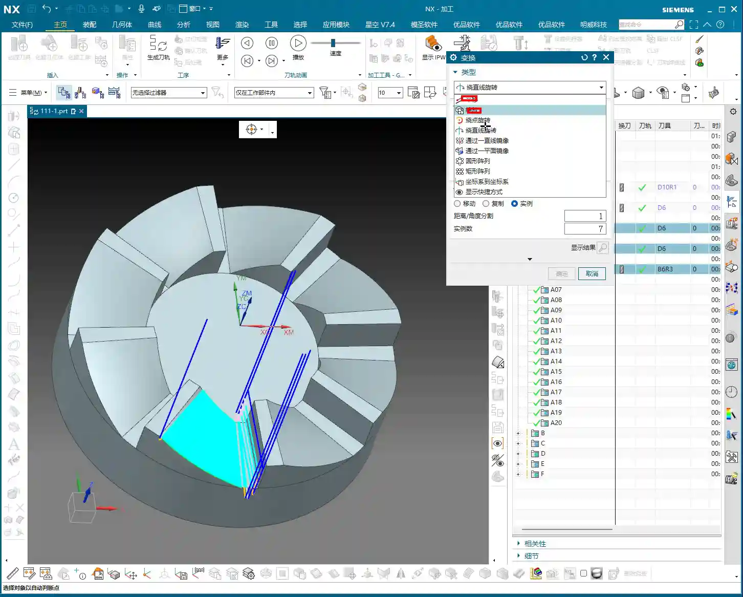
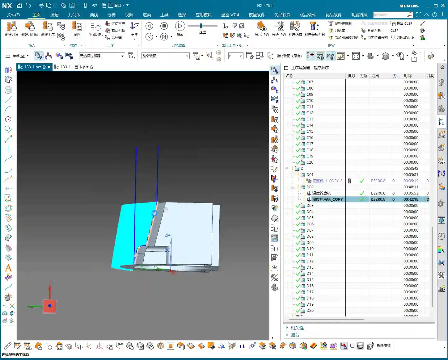
    Since the back face and Face B are similar, we’ll directly copy the roughing program from Face B. But remember, the face must be updated to select the new back face as the machining surface. Tool parameters and stock allowance will follow the previous Φ32mm (approx. 1.26 inch), R0.8mm (approx. 0.03 inch) tool, ensuring ample stock. While tool path reuse is convenient, the actual conditions of each face and each hole may differ, so parameter adjustment is essential—no cutting corners!

    One point to note here is the choice between Perpendicular to tool axis and Parallel to tool axis. When machining inclined or curved surfaces, this option directly affects the tool’s cutting posture and efficiency. Here, we’ll simply select a face and let the software automatically generate the path. During machining, do not use a Reciprocate (zig-zag) pattern; instead, follow the contour directly. This will result in more stable cutting.

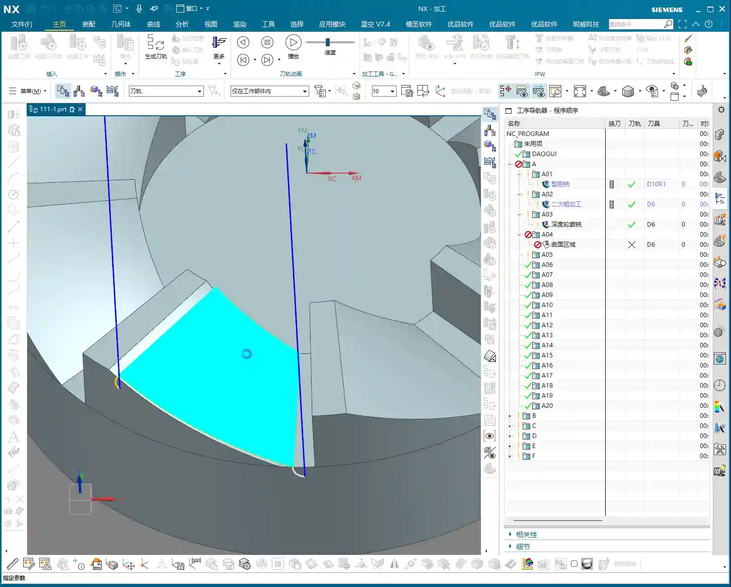
    After roughing is complete, check again if there are any areas still needing roughing. Oh, right, the side faces and internal holes haven’t been roughed yet!

    For these internal holes, we can perform roughing using a Helical Ramp method, or directly use Trochoidal Milling, as long as it doesn’t damage the tool and is efficient. We’ll still use the Φ32mm (approx. 1.26 inch), R0.8mm (approx. 0.03 inch) tool. The Depth of Cut (DOC) can be larger, for example, 21.5mm (approx. 0.85 inch) (I deliberately went a bit deeper here; actual depth should be based on the drawing), leaving a 0.2mm (approx. 0.008 inch) stock allowance. The entry and exit paths must also be adjusted for safety. Pay attention to tool stick-out length; mine is a bit long here, but it should be shortened for actual operation.

    Finishing Strategy for Blind Holes and Irregular Holes

    For blind holes or irregular holes that may appear on the back face, the finishing strategy is similar to the front face. First, use a small-diameter flat end mill to finish the side walls, ensuring perpendicularity and surface finish. For blind hole bottoms, if high precision is required, a bottom corner cleanup tool must be used for corner cleanup to ensure a flat bottom. These details are crucial for determining the final product accuracy. Remember, ±0.005mm (approx. ±0.0002 inch) accuracy is achieved through this cumulative attention to detail and optimization.

    Summary: Pitfall Avoidance Guide

    Alright, today we’ve covered the roughing and finishing of multi-process parts, as well as hole processing. Finally, I’ll summarize a few points for you—these are pitfall avoidance experiences gained from hands-on practice:

    1. Datum First, Secure Clamping: Any machining operation must start from the most stable and precise datum. Poor clamping renders all efforts futile. During roughing, ensuring rigidity is even more critical.
    2. Stock Control, Distinct Stages: Leave sufficient stock for roughing, then uniformly remove it during finishing. Don’t attempt a single-pass finish; that will only lead to a loss of both accuracy and surface quality. Typically, roughing leaves 0.15-0.5mm (approx. 0.006-0.02 inch), and finishing leaves 0.05-0.1mm (approx. 0.002-0.004 inch). For special materials like titanium alloys and high-temperature nickel-based alloys, stock control must be even more cautious due to their severe work hardening tendency.
    3. Tool Selection, Material-Specific: Different materials and different machining stages require different tools. For example, a Φ32mm (approx. 1.26 inch), R0.8mm (approx. 0.03 inch) tool is efficient for roughing; a Φ10mm (approx. 0.39 inch) flat end mill is suitable for finishing side walls and corner cleanup. Don’t expect one tool to do everything; that’s impossible. For high-temperature alloys, carbide tools must be used, and cutting parameters should be slow to prevent chipping.
    4. Tool Path Optimization, Balancing Efficiency and Stability: The tool path generated by the software isn’t necessarily optimal; always combine it with real-world considerations. Minimize air cuts, avoid sharp turns, and maintain stable cutting forces. For thin-walled or easily deformable parts, consider gradual cutting strategies, or even multi-layer machining.
    5. Drawing is King, Verify Dimensions: Never guess dimensions based on experience, especially for hole depth, diameter, and position. The drawing is your bible; cross-reference it repeatedly before machining.
    6. Combine “See, Hear, Feel”: Don’t just stare at the NX simulation on the screen. On the actual machine, observe the color and shape of the cutting sparks, whether the cutting sound is smooth, and if the chip formation is normal. This is real skill you won’t learn from books. If the cutting sparks are white or the sound is harsh, it usually indicates tool wear or unsuitable parameters.
    7. Prevent Heat Treatment Deformation: If the workpiece requires heat treatment, machining allowances and clamping methods must be considered in advance, reserving sufficient finishing stock to compensate for deformation.
    8. Accuracy Compensation: When dealing with accuracies of ±0.005mm (approx. ±0.0002 inch), machine tool inherent errors, tool wear, and ambient temperature can all have an impact. Siemens NX allows for tool compensation, cutter compensation, and even direct fine-tuning in the G-code. However, the best approach is to optimize processes and parameters at the source to minimize cumulative errors.

    In our line of work, you can’t just know how to push buttons; you need to understand why you’re pushing them. These tricks of the trade are accumulated through time and expense. I hope you all avoid unnecessary detours!

    👤 About the Author:
    The author is a veteran CNC machining professional with 15 years of industry experience, specializing in UG NX programming. This article is an original work representing personal practical insights.

    ⚠️ Copyright Notice: Unauthorized reproduction or distribution without prior communication is strictly prohibited.

  • Mold Part Siemens NX Programming Practical Guide: Master Wang Details Toolpath Segmentation for Enha

    📝 Key Takeaways: ** Master Wang details practical Siemens NX programming for mold parts. From roughing to finishing, he elaborates on tool selection, stepover and depth of cut, allowance control, and toolpath segmentation strategies. Emphasis is placed on optimization techniques for “Contour Milling” on sloped surfaces and “Z-Level Milling” for side walls, along with how to resolve issues like unnecessary tool lifts and missed cuts by adjusting parameters. Practical application is key, and these pitfall avoidance tips will help you boost efficiency and precision. **

    Overall Machining Strategy and Tool Selection

    Process Sequence: Roughing First, Then Finishing, Step-by-Step

    Listen up, lads. In mold making, process is everything. Once this area is done, the next step is roughing with an R2 ball end mill to quickly remove the excess material. After that, make sure the part surface is finished smooth, and finally, meticulously clean up the side walls. Don’t mess up the sequence; if you do, it’s rework, and that’s not a joke – that’s money!

    Tool Selection for Mold Surface Finishing

    Once roughing is done, for surface finishing, you must use a ball end mill. As I said earlier, a small R2 ball end mill, or larger ones like R4, R6, are all acceptable, depending on the workpiece size and your desired machining allowance. For mold parts like this, we typically use a 16R4 ball end mill. Its stepover is 0.2mm, and depth of cut is 5mm. These parameters depend on your tool rigidity, material hardness, and machine tool stiffness. Don’t blindly copy them; too small, and efficiency drops; too large, and you risk chipping the tool. Especially with depth of cut – if you take too aggressive a cut, the tool is finished. And don’t ever use a flat end mill to finish curved surfaces; that’s just foolishness!

    Precise Definition of Stock and Machining Area

    Selecting the stock and machining faces is fundamental, but also where mistakes are most often made. Miss a selection, and it won’t be machined; over-select, and you’ll cut what shouldn’t be cut, and then it’s too late to cry. Choosing the correct stock is crucial, otherwise, the software calculates endlessly, and in actual machining, you’ll either have tool crashes or air cuts, wasting time, effort, and material. Especially for parts with root areas, if roughing has already cleared most of it, you can wait to address it when finishing the side walls, avoiding redundant machining. Here, we’ve decided to only clear the top, leaving the bottom untouched. Use the ‘Boundary Intersection’ function to lock down the toolpath boundary precisely, with the final pass stopping exactly at the specified point. This method ensures high machining efficiency without interfering with other areas.

    Detailed Toolpath Strategies for Critical Areas

    Toolpath Optimization for Sloped Areas using “Contour Milling”

    When encountering areas with significant slopes, the most effective toolpath in Siemens NX is ‘Contour Milling’. It follows the surface, producing an exceptionally good surface finish. However, be wary of unnecessary tool lifts/retracts! During toolpath simulation, if you see the tool frequently lifting and re-engaging, there’s definitely an issue. Excessive tool lifts not only reduce efficiency but also tend to leave marks at the entry and exit points. If you spot unnecessary tool lifts, check your toolpath parameters, such as lead-in/lead-out methods and angle settings. Here, I adjusted the lead-in/lead-out angle to 45 degrees, and the tool lifts disappeared immediately. These little tricks aren’t found in textbooks; they’re accumulated through experience.

    Step-by-Step Finishing of Side Walls and Bottom Surfaces

    For finishing side walls and bottom surfaces, I typically start by using a flat end mill or a radius end mill to finish the bottom surface clean, setting the machining allowance directly to zero. Then, I switch to a 12R2 tool and use either ‘Z-Level Milling’ or ‘Follow Periphery’ methods to perform a finishing pass on the side walls. For side walls, you can leave a small allowance, for instance, 0.5mm, which facilitates subsequent final polishing or fine finishing. The machining direction is from top to bottom; this is climb milling, which provides good chip evacuation and a high surface finish. For complex geometries, I often use ‘Mixed Milling’ to achieve smoother toolpaths, reduce unnecessary tool lifts, and enhance surface quality.

    Machining Allowance Control and Feed Rate Adjustment

    Machining allowance is a profound topic. Leaving 0.5mm on side walls and zero on bottom surfaces balances both accuracy and efficiency. But look at the allowance after roughing: 0.35mm – that’s a bit too much! Next time you rough, you can reduce it to around 0.2mm, or even smaller, depending on the material and tool. Leaving too much allowance means the finishing pass has to take more cuts, wasting time and tool life. Also, regarding feed rate (cutting speed), setting it to 400 in Siemens NX is already the maximum; don’t push it higher. The machine has its limits; exceeding them will either cause an error or lead to excessive machine chatter, affecting machining quality. Remember, stability is paramount!

    Siemens NX Operation Tips and Efficiency Improvement

    Parameter Adjustments to Avoid Unnecessary Tool Lifts

    I’ve emphasized this many times: unnecessary tool lifts are a major machining taboo. Every time the tool lifts and re-engages, it not only wastes time but can also leave subtle tool marks on the workpiece surface, affecting the surface finish. Besides adjusting the lead-in/lead-out angle, you can also try adjusting parameters like connection methods and retract height. The goal is singular: to make the toolpath as smooth as possible and minimize unnecessary tool lifts. For example, by adjusting the angle to 45 degrees here, the issue of unnecessary tool lifts was resolved instantly.

    Precise Control of Toolpath Boundaries and Depth

    If the toolpath finishes and you find the machining is incomplete, don’t rush to blame the software. First, check your cutting levels depth and toolpath extension amount. For example, if it wasn’t machining to the bottom here, I directly added 2.2mm downwards in the cutting levels, and the problem was solved. This is the kind of detailed work required to control accuracy to the ±0.005mm level. As for the hole features, those are fundamental basics; program them yourself using hole milling. I won’t demonstrate it here; it’s too elementary. Of course, some auxiliary features that don’t affect the current toolpath can be deselected to reduce calculation time.

    Toolpath Simulation and Verification

    Toolpath simulation is your last line of defense before going to the machine! Every time you finish programming, regardless of the complexity, diligently simulate it. Especially for roughing toolpaths, focus on checking for any missed cuts, gouges (overcuts), or tool collision risks. During simulation, you can speed it up appropriately to get a general overview. As for those auxiliary bodies, once machining is complete, hide them from view to avoid clutter and prevent thinking some strange extra parts have appeared on the component.

    Summary: Pitfall Avoidance Guide

    Alright, we’ve covered a lot of practical knowledge today. Finally, let me summarize a few pitfall avoidance tips for you, all derived from my 15 years of hands-on experience:

    1. Strictly follow the machining sequence: Rough first, then finish, step by step. Don’t rush for quick results.
    2. Tool selection demands attention: For mold surface finishing, the ball end mill is your primary tool. Proper parameter settings will yield twice the results with half the effort.
    3. Machining allowance is a science: Don’t leave too much roughing allowance (0.35mm is already excessive). For finishing, zero out the allowance where appropriate, and leave it precisely where needed.
    4. Eliminate unnecessary tool lifts to boost efficiency: Continuously inspect toolpaths, adjust lead-in/lead-out strategies and angles (e.g., 45 degrees) to avoid unnecessary tool lifts.
    5. Simulation and verification are paramount: Before every machine run, diligently simulate the toolpath and check for all potential errors.
    6. Be bold yet meticulous with parameter adjustments: For instance, if machining is incomplete, confidently adjust cutting levels or extension amounts (e.g., add 2.2mm downwards), but calculate precisely; don’t guess.
    7. Keep material properties in mind: Cutting parameters vary significantly for different materials, from common aluminum to titanium alloys and high-temperature nickel-based superalloys – always be aware.
    8. Fixturing solutions are fundamental to machining: Even the best toolpath is useless if the workpiece isn’t securely fixtured.
    9. Master the grinding of custom tools: Sometimes standard tools won’t cut it; being able to grind your own suitable tool is true skill.

    These are the tools of your trade for the future. Study them carefully, don’t just listen with your ears – think with your mind, and practice with your hands!

    👤 About the Author:
    The author is a veteran CNC machining professional with 15 years of industry experience, specializing in UG NX programming. This article is an original work representing personal practical insights.

    ⚠️ Copyright Notice: Unauthorized reproduction or distribution without prior communication is strictly prohibited.

  • Master Wang’s Guide to Finishing Rotary Parts: Practical Side Wall, Bottom Surface, and Corner Clean

    📝 Key Takeaways: Hello everyone, this is Master Wang. Last time, we covered roughing. This time, the focus is on finishing rotary parts. From side walls to bottom surfaces, and then to root corner cleanup, I’ll walk you through programming efficient, high-quality toolpaths using Siemens NX. I’ll share practical tips you won’t find in textbooks, such as how to optimize tool retractions, prevent overcutting, and tackle various machining challenges. My goal is for you to not just program, but truly understand the machine and the process.

    Step One: Finishing Side Walls and Bottom Surfaces – Refined Application of Depth Profile Milling

    Listen up, last time we thoroughly covered roughing and semi-roughing. This time, we’re heading straight into finishing, focusing on the part’s side walls and bottom surfaces. Especially that bottom area – we might have left some stock last time, but this time it needs to be completely cleaned, leaving no blind spots.

    Practical Tool Selection and Machining Area Definition

    First, open your NX software. We’ll select a “Depth Profile Milling” operation. For tooling, we’ll directly choose our commonly used D6 flat end mill; this tool will handle the corner cleanup and side walls. As for the machining area, you can initially box-select the entire part; that’s fine, we’ll precisely define it later.

    Hold on, what we need to do is specifically select these two areas: the side walls and the bottom surface. Remember, precision selection is better than broad selection. This avoids many unnecessary issues and computational load, improving program generation efficiency.

    Depth of Cut and Multi-Pass Strategy

    This program is primarily for finishing passes on the side walls. As I mentioned last time, the stepover for side walls should be tighter to achieve a smoother finish. For the bottom surface, we’ll machine down to a depth of -18mm. Of course, to be safe, you can adjust it slightly shallower, say -17mm, to leave a bit of stock for the final finishing pass.

    Here’s the critical point: that last 1 millimeter (approx. 0.04 inch) of stock on the bottom surface (for example, from -17mm to -18mm) – you absolutely cannot take it off in a single pass! Doing so risks chatter or tool breakage, and the resulting surface won’t be flat. We need to split it into multiple layers, for instance, taking 0.3mm (approx. 0.012 inch) per Depth of Cut (DOC). By cutting in two to three layers this way, the cut will be stable, and the finish will be superior. Don’t just rely on software simulation; pay attention to the cutting sparks and the actual forces on the tool!

    Additionally, the top 5 millimeters (approx. 0.2 inch) of the side wall should also receive extra finishing passes to improve its flatness. During the finishing pass stage, we won’t leave any stock; it’s a direct one-pass finish.

    Cutting Parameters and Safety Strategies

    For the cutting order, we’ll select Depth First. As for stepover, a linear cut at 55% or 60% is fine; this depends on your tool’s strength and material properties. However, I typically disable extension to avoid unnecessary toolpaths.

    The program has generated, and the cutting depth control is fine. But look at this rapid move – it plunges directly into the side wall! This is unacceptable! A machine tool isn’t a computer simulation; this kind of move risks a collision. At best, you’ll scrap the tool and workpiece; at worst, you’ll damage the machine!

    Therefore, we need to go into “Non-Cutting Moves” and modify the rapid transfer. For safety, retract to the stock surface; that 3-millimeter (approx. 0.12 inch) height is acceptable. This provides sufficient safe retraction space for the tool. This is a crucial safety procedure, remember that!

    Here’s another trick: if the toolpath keeps failing to generate or takes excessive detours, it’s likely because a previously selected face is restricting it. Just select the bottom surface and the two side walls; don’t select the upper faces, let the tool move freely! Simplifying your selections often resolves major issues.

    Finally, overcut checking is fundamental! Don’t assume everything is fine just because the program generated. One overcut can undo all your previous work, or even scrap the part.

    Step Two: Corner Cleanup and Angled Surface Finishing – Surface Drive and Guide Curve

    All right, the side walls and bottom surface are finished. Next, let’s address the root area of this part. After corner cleanup, we also need to perform contour milling on this angled surface. What command do you think is suitable?

    Corner Cleanup Toolpath: Surface Drive is the Correct Approach

    Some might think of using a “Guide Curve” for corner cleanup. But listen up: Guide Curve only supports ball end mills. How can a ball end mill perform corner cleanup? It simply can’t clean effectively! If the root has a sharp corner or small radius, a ball end mill can’t reach the bottom. Others might suggest using “Streamline” offset lines, which can also work, but that’s too much hassle—offsetting lines, selecting them—it’s highly inefficient!

    So, the most direct and effective method is our Surface Drive. This command is specifically designed for this! We’ll still use our D6 flat end mill. This time, there’s no need to select a machining area; just select the “drive face.”

    Pay close attention to the cutting direction; we’ll set it to Material Reverse and use Zigzag machining for higher efficiency. For corner cleanup, a 0.1-millimeter (approx. 0.004 inch) stepover! When performing corner cleanup with a D6 flat end mill, a small stepover is crucial for a clean cut; otherwise, the finished surface won’t be flat, and all your effort will be wasted! Remember, finishing passes require attention to fine details; no need to change tolerances, just calculate the toolpath directly.

    Toolpath Trimming: Precise Control of Machining Area

    The program has generated, but it’s currently cutting from top to bottom, and we only need that small root area at the bottom. This is where the Trimming function comes in – listen up, this is key to boosting efficiency!

    Within “Cutting Area,” locate “Surface Percentage.” See, we initially clicked this arrow (pointing at the direction), so Start Trim calculates from the top, and End Trim goes to the bottom. We need to shorten it to only machine the root area, which means modifying Start Trim. For example, changing it to 97% will make it cut only the very last portion. You’ll need to experiment a few times to find the appropriate percentage until the toolpath precisely covers the root area. This all comes from experience; you have to get hands-on.

    Exploration: Applying Guide Curves and Optimizing Retract Moves

    While Surface Drive works well for corner cleanup, to broaden your understanding of different methods, we can also try using a Guide Curve to machine this angled surface. You might not have used it much before, so let’s get some hands-on practice. Honestly, for machining such surfaces, any command will do – Contour Milling or Surface Drive, both are viable. The key is to find what’s best for the current situation; don’t fret, nothing is too difficult!

    For the Guide Curve operation, we’ll use a D6 ball end mill this time. First, select the first guide curve, then the second. It’s that simple; nothing complicated.

    After the program generates, you’ll notice a problem: this retract move (the pink rapid move lines in the program) is retracting excessively high, which is a huge waste of time! The machine running idle costs money! This needs to be fixed!

    The height of this retract move is directly related to the stock distance parameter. Let’s reduce it, for example, to 1mm (approx. 0.04 inch). Recalculate, and see? It’s much lower now, isn’t it? Idle cutting time is instantly saved – that’s efficiency! Don’t underestimate these one or two millimeters; over years, the accumulated cost savings are significant.

    Final Checks and Program Transformation

    All right, by now, all of our finishing pass programs are complete.

    Overcut Check: The Last Line of Defense Before Machining

    Next, overcut checking – this is absolutely mandatory every time. See, no alarms means no overcuts. If there were, the software would definitely throw an error. Never skip this step, or you’ll be devastated if the part is scrapped!

    Simulation and Saving: Preventing Software Crashes

    Then, save it! Remember, develop good habits. Sometimes, simulating directly can crash the software, leaving you with nothing. These are lessons learned the hard way. After saving, let’s simulate and check the results!

    The simulation might not look absolutely perfect, especially with a D6 flat end mill (meaning a sharp corner/R0 tool); some details might not display completely. However, the actual machined part will be fine. I’ve machined these types of parts before with excellent results. These examples I share with you are all from parts I’ve actually machined. With that, this part is now complete.

    Program Transformation (Mirroring)

    Final step, don’t forget to transform your previous roughing programs, meaning mirror them. This part is symmetrical, so some programs won’t require transformation, such as the side wall and bottom surface finishing passes. However, the corner cleanup might. Select the transformation object – it’s a simple task. With that, a complete set of machining programs for this rotary part is all done!

    Summary: Pitfall Avoidance Guide

    • Depth of Cut (DOC) Control: Divide the final 1mm (approx. 0.04 inch) of stock into multiple cutting layers; never take it off in a single pass, as this risks chatter or tool breakage, affecting surface finish.
    • Rapid Move Optimization: Disable direct plunge-style rapid moves. Set a safe retract move height (retract to the stock surface) via “Non-Cutting Moves” to prevent collisions.
    • Machining Area Simplification: When toolpaths exhibit abnormal behavior (failing to generate or excessive detours), check and simplify the selection of “Machining Areas” to avoid unnecessary restrictions.
    • Corner Cleanup Tooling and Strategy: For corner cleanup, a flat end mill combined with Surface Drive is preferred; Guide Curve only supports ball end mills and is unsuitable for root corner cleanup.
    • Precise Toolpath Trimming: Make good use of “Surface Percentage” to precisely control the start and end points of the toolpath, avoiding idle cuts or machining unnecessary areas.
    • Retract Move Height Optimization: Adjust the “stock distance” parameter to reduce unnecessary retract move heights, saving idle cutting time and improving machining efficiency.
    • Overcut Checking: Always perform an overcut check after generating each program; this is the final line of defense for ensuring part quality.
    • Timely Saving: Before performing simulations or complex operations, cultivate the habit of saving frequently to prevent software crashes from causing data loss.

    [VIDEO_HERE]

    [EXCERPT] Hello everyone, this is Master Wang. Last time, we covered roughing. This time, the focus is on finishing rotary parts. From side walls to bottom surfaces, and then to root corner cleanup, I’ll walk you through programming efficient, high-quality toolpaths using Siemens NX. I’ll share practical tips you won’t find in textbooks, such as how to optimize tool retractions, prevent overcutting, and tackle various machining challenges. My goal is for you to not just program, but truly understand the machine and the process.

    Step One: Finishing Side Walls and Bottom Surfaces – Refined Application of Depth Profile Milling

    Listen up, last time we thoroughly covered roughing and semi-roughing. This time, we’re heading straight into finishing, focusing on the part’s side walls and bottom surfaces. Especially that bottom area – we might have left some stock last time, but this time it needs to be completely cleaned, leaving no blind spots.

    Practical Tool Selection and Machining Area Definition

    First, open your NX software. We’ll select a “Depth Profile Milling” operation. For tooling, we’ll directly choose our commonly used D6 flat end mill; this tool will handle the corner cleanup and side walls. As for the machining area, you can initially box-select the entire part; that’s fine, we’ll precisely define it later.

    Hold on, what we need to do is specifically select these two areas: the side walls and the bottom surface. Remember, precision selection is better than broad selection. This avoids many unnecessary issues and computational load, improving program generation efficiency.

    Depth of Cut and Multi-Pass Strategy

    This program is primarily for finishing passes on the side walls. As I mentioned last time, the stepover for side walls should be tighter to achieve a smoother finish. For the bottom surface, we’ll machine down to a depth of -18mm. Of course, to be safe, you can adjust it slightly shallower, say -17mm, to leave a bit of stock for the final finishing pass.

    Here’s the critical point: that last 1 millimeter (approx. 0.04 inch) of stock on the bottom surface (for example, from -17mm to -18mm) – you absolutely cannot take it off in a single pass! Doing so risks chatter or tool breakage, and the resulting surface won’t be flat. We need to split it into multiple layers, for instance, taking 0.3mm (approx. 0.012 inch) per Depth of Cut (DOC). By cutting in two to three layers this way, the cut will be stable, and the finish will be superior. Don’t just rely on software simulation; pay attention to the cutting sparks and the actual forces on the tool!

    Additionally, the top 5 millimeters (approx. 0.2 inch) of the side wall should also receive extra finishing passes to improve its flatness. During the finishing pass stage, we won’t leave any stock; it’s a direct one-pass finish.

    Cutting Parameters and Safety Strategies

    For the cutting order, we’ll select Depth First. As for stepover, a linear cut at 55% or 60% is fine; this depends on your tool’s strength and material properties. However, I typically disable extension to avoid unnecessary toolpaths.

    The program has generated, and the cutting depth control is fine. But look at this rapid move – it plunges directly into the side wall! This is unacceptable! A machine tool isn’t a computer simulation; this kind of move risks a collision. At best, you’ll scrap the tool and workpiece; at worst, you’ll damage the machine!

    Therefore, we need to go into “Non-Cutting Moves” and modify the rapid transfer. For safety, retract to the stock surface; that 3-millimeter (approx. 0.12 inch) height is acceptable. This provides sufficient safe retraction space for the tool. This is a crucial safety procedure, remember that!

    Here’s another trick: if the toolpath keeps failing to generate or takes excessive detours, it’s likely because a previously selected face is restricting it. Just select the bottom surface and the two side walls; don’t select the upper faces, let the tool move freely! Simplifying your selections often resolves major issues.

    Finally, overcut checking is fundamental! Don’t assume everything is fine just because the program generated. One overcut can undo all your previous work, or even scrap the part.

    Step Two: Corner Cleanup and Angled Surface Finishing – Surface Drive and Guide Curve

    All right, the side walls and bottom surface are finished. Next, let’s address the root area of this part. After corner cleanup, we also need to perform contour milling on this angled surface. What command do you think is suitable?

    Corner Cleanup Toolpath: Surface Drive is the Correct Approach

    Some might think of using a “Guide Curve” for corner cleanup. But listen up: Guide Curve only supports ball end mills. How can a ball end mill perform corner cleanup? It simply can’t clean effectively! If the root has a sharp corner or small radius, a ball end mill can’t reach the bottom. Others might suggest using “Streamline” offset lines, which can also work, but that’s too much hassle—offsetting lines, selecting them—it’s highly inefficient!

    So, the most direct and effective method is our Surface Drive. This command is specifically designed for this! We’ll still use our D6 flat end mill. This time, there’s no need to select a machining area; just select the “drive face.”

    Pay close attention to the cutting direction; we’ll set it to Material Reverse and use Zigzag machining for higher efficiency. For corner cleanup, a 0.1-millimeter (approx. 0.004 inch) stepover! When performing corner cleanup with a D6 flat end mill, a small stepover is crucial for a clean cut; otherwise, the finished surface won’t be flat, and all your effort will be wasted! Remember, finishing passes require attention to fine details; no need to change tolerances, just calculate the toolpath directly.

    Toolpath Trimming: Precise Control of Machining Area

    The program has generated, but it’s currently cutting from top to bottom, and we only need that small root area at the bottom. This is where the Trimming function comes in – listen up, this is key to boosting efficiency!

    Within “Cutting Area,” locate “Surface Percentage.” See, we initially clicked this arrow (pointing at the direction), so Start Trim calculates from the top, and End Trim goes to the bottom. We need to shorten it to only machine the root area, which means modifying Start Trim. For example, changing it to 97% will make it cut only the very last portion. You’ll need to experiment a few times to find the appropriate percentage until the toolpath precisely covers the root area. This all comes from experience; you have to get hands-on.

    Exploration: Applying Guide Curves and Optimizing Retract Moves

    While Surface Drive works well for corner cleanup, to broaden your understanding of different methods, we can also try using a Guide Curve to machine this angled surface. You might not have used it much before, so let’s get some hands-on practice. Honestly, for machining such surfaces, any command will do – Contour Milling or Surface Drive, both are viable. The key is to find what’s best for the current situation; don’t fret, nothing is too difficult!

    For the Guide Curve operation, we’ll use a D6 ball end mill this time. First, select the first guide curve, then the second. It’s that simple; nothing complicated.

    After the program generates, you’ll notice a problem: this retract move (the pink rapid move lines in the program) is retracting excessively high, which is a huge waste of time! The machine running idle costs money! This needs to be fixed!

    The height of this retract move is directly related to the stock distance parameter. Let’s reduce it, for example, to 1mm (approx. 0.04 inch). Recalculate, and see? It’s much lower now, isn’t it? Idle cutting time is instantly saved – that’s efficiency! Don’t underestimate these one or two millimeters; over years, the accumulated cost savings are significant.

    Final Checks and Program Transformation

    All right, by now, all of our finishing pass programs are complete.

    Overcut Check: The Last Line of Defense Before Machining

    Next, overcut checking – this is absolutely mandatory every time. See, no alarms means no overcuts. If there were, the software would definitely throw an error. Never skip this step, or you’ll be devastated if the part is scrapped!

    Simulation and Saving: Preventing Software Crashes

    Then, save it! Remember, develop good habits. Sometimes, simulating directly can crash the software, leaving you with nothing. These are lessons learned the hard way. After saving, let’s simulate and check the results!

    The simulation might not look absolutely perfect, especially with a D6 flat end mill (meaning a sharp corner/R0 tool); some details might not display completely. However, the actual machined part will be fine. I’ve machined these types of parts before with excellent results. These examples I share with you are all from parts I’ve actually machined. With that, this part is now complete.

    Program Transformation (Mirroring)

    Final step, don’t forget to transform your previous roughing programs, meaning mirror them. This part is symmetrical, so some programs won’t require transformation, such as the side wall and bottom surface finishing passes. However, the corner cleanup might. Select the transformation object – it’s a simple task. With that, a complete set of machining programs for this rotary part is all done!

    Summary: Pitfall Avoidance Guide

    • Depth of Cut (DOC) Control: Divide the final 1mm (approx. 0.04 inch) of stock into multiple cutting layers; never take it off in a single pass, as this risks chatter or tool breakage, affecting surface finish.
    • Rapid Move Optimization: Disable direct plunge-style rapid moves. Set a safe retract move height (retract to the stock surface) via “Non-Cutting Moves” to prevent collisions.
    • Machining Area Simplification: When toolpaths exhibit abnormal behavior (failing to generate or excessive detours), check and simplify the selection of “Machining Areas” to avoid unnecessary restrictions.
    • Corner Cleanup Tooling and Strategy: For corner cleanup, a flat end mill combined with Surface Drive is preferred; Guide Curve only supports ball end mills and is unsuitable for root corner cleanup.
    • Precise Toolpath Trimming: Make good use of “Surface Percentage” to precisely control the start and end points of the toolpath, avoiding idle cuts or machining unnecessary areas.
    • Retract Move Height Optimization: Adjust the “stock distance” parameter to reduce unnecessary retract move heights, saving idle cutting time and improving machining efficiency.
    • Overcut Checking: Always perform an overcut check after generating each program; this is the final line of defense for ensuring part quality.
    • Timely Saving: Before performing simulations or complex operations, cultivate the habit of saving frequently to prevent software crashes from causing data loss.

    👤 About the Author:
    The author is a veteran CNC machining professional with 15 years of industry experience, specializing in UG NX programming. This article is an original work representing personal practical insights.

    ⚠️ Copyright Notice: Unauthorized reproduction or distribution without prior communication is strictly prohibited.

  • Practical Siemens NX Deep Contour Milling: The Ultimate Tool for 3D Surface Machining – Master Wang’

    📝 Key Takeaways: NX Deep Contour Milling: A Practical Guide to 3D Surface Finishing

    Master Wang’s Talk: Deep Contour Milling – What Exactly Is It?

    Hello everyone, I’m Old Wang. Today, let’s skip the small talk and dive right into the main course – Deep Contour Milling. You might have read about this in textbooks, but understanding how and when to actually use it involves a lot of practical knowledge.

    Listen up, Deep Contour Milling, as the name suggests, is for machining “contours.” So, how is this different from the “Planar Profile Milling” we discussed before? The difference is significant! While both machine contours, Planar Profile Milling is rigid; it only deals with **straight, vertical 2D sidewalls**. Give it an inclined surface or an arc, and it’s completely lost.

    Our Deep Contour Milling, however, is a “versatile player.” Its greatest strength is its ability to handle **complex 3D surfaces**! Whether it’s inclined planes, fillets, radii, or various freeform surfaces – as long as it’s a sidewall, it can mill it precisely and smoothly. That’s why it’s our “go-to tool” for finishing, especially for precisely machining complex surface sidewalls.

    Machining Strategy: The Frontrunner for Finishing

    Before we dive into the NX operations, let’s get our strategy straight. Deep Contour Milling is specifically for **finishing, surfacing sidewalls, and Corner Cleanup**. Don’t even think about using it for Roughing; that’s like using a sledgehammer to crack a nut – it’s inefficient and puts unnecessary stress on the tool.

    • Roughing: Remember, there are dedicated operations for Roughing, such as Cavity Mill, Face Milling, etc. These are designed for aggressive material removal. First, use Roughing to remove most of the material and mill out the blank’s basic shape.
    • Finishing: By the time Deep Contour Milling comes into play, there should only be a thin layer of material remaining on the part. At this point, we use **small-diameter ball end mills or bull nose end mills**, combined with Deep Contour Milling, to finish the sidewalls, achieving the required accuracy and surface finish. Of course, for some tight corners or blind spots, you’ll need even smaller tools, or even custom-ground tools.

    Sometimes you’ll see the “Deep Spiral” option; that’s actually a specialized helical feed strategy within Deep Contour Milling. It’s also for finishing sidewalls, and the principle is similar. Let’s put that aside for now and focus on the main concept.

    Key NX Operations: Follow Master Wang and Avoid Years of Trial and Error

    Step One: Work Coordinate System (WCS) Setup

    This step is a common topic, but it still needs emphasizing. WCS setup is the foundation of all programming. This time, you don’t have to place it at the part’s center. You can place it at any corner, for example, a “pinch point” on the model, then rotate it 180 degrees so the X-axis aligns with your preferred machining direction. Remember, this is just a matter of preference and doesn’t affect your final programming logic or toolpath.

    Each time, we must first create a **Workpiece** geometry and then specify our **Part** and **Blank**. However, since Deep Contour Milling is mainly for finishing, the blank has usually been largely machined already. So sometimes, you can directly delete the blank and keep only the part, which speeds up software calculations.

    Step Two: Specifying the Machining Area – Avoiding the “Select All” Trap

    This is a crucial point! After entering the Deep Contour Milling operation, besides specifying the part, the most critical step is **”Specify Cut Area.”** Why emphasize this? Because new programmers often have a habit of blindly selecting the entire part. The tool then runs unnecessarily over areas that don’t need machining, which is a waste of time and increases wear.

    The essence of Deep Contour Milling lies in its ability to precisely machine your desired **local sidewalls**. For instance, if you only want to finish the sidewall of a specific hole or the inclined surface of a certain step, you must **explicitly specify these areas**. If you don’t, it won’t know where to machine.

    During the operation, open the “Specify Cut Area” option, then directly select the faces you want to machine on the model. This way, the toolpath will only be generated within this specific area, ensuring both efficiency and precision.

    Step Three: Tool Selection and Toolpath Generation

    Tool selection depends on the features you intend to machine. For example, to clean up an R5 fillet, you can’t possibly use a D10 tool, can you? Typically, flat end mills or bull nose end mills are used for finishing sidewalls, while ball end mills are commonly used for Corner Cleanup. Remember to choose the right tool, such as a D10 end mill for finishing a relatively large bore wall.

    Once all parameters are set, it’s time for the “stroll” phase – toolpath generation. You young folks, don’t just stare at the computer screen. After the toolpath is generated, you must **carefully simulate and inspect it**. Check if the tool’s trajectory is reasonable, if there are any air cuts, overcuts, or areas prone to heavy Depth of Cut (DOC). Software simulation alone won’t show you machining sparks, so experience and visual inspection are indispensable.

    Master Wang’s Pro Tips: Tricks to Boost Efficiency

    NX View Rotation Trick

    When rotating models in NX, do you often find the model flying off, not rotating to the position you want to see? That’s because you haven’t identified the correct center point for rotation.

    Listen up, here’s a little trick: When you need to observe the model around a specific point (like a hole or a fillet), **hold down the middle mouse button on that point, don’t release it**, then drag the mouse to rotate. You’ll then notice that the model rotates around the point you’re holding, making observation much easier! This trick isn’t something textbooks necessarily teach you; it’s something we’ve picked up through hard work and experience on the shop floor.

    Leverage NX Effectively to Avoid Repetitive Work

    Many operations in NX are interconnected, such as “Specify Part,” “Specify Blank,” and “Specify Cut Boundaries.” Once you’ve learned them, there’s not much more to say. Practice more, think more. Only by mastering these fundamentals can you free up your mind to explore more advanced techniques.

    In our next lesson, we’ll delve deeper and thoroughly review the other options within Deep Contour Milling. That’s all for today. See you next time!

    Summary: Guide to Avoiding Common Mistakes

    1. DO NOT use Deep Contour Milling for Roughing! It’s a powerful tool for Finishing, not a brute-force tool for Roughing. Using it for Roughing is not only inefficient but also prone to tool wear and part damage.
    2. Precisely Specify the Cut Area! Don’t be lazy, and don’t “select all.” Select the specific sidewall surfaces that require machining to ensure efficient and precise toolpaths.
    3. Inspect the Toolpath! After the toolpath is generated, always simulate it carefully. Observe the tool’s entry and exit moves, and its cutting path, to confirm there are no overcuts, collisions, or air cuts. This will save you a lot of trouble compared to rework later.
    4. Understand the Difference Between 2D and 3D! Planar Profile Milling only handles straight walls, while Deep Contour Milling can tackle all kinds of sidewall surfaces. However, neither is suitable for machining large flat surfaces. Choosing the right operation will make your work twice as effective with half the effort.

    👤 About the Author:
    The author is a veteran CNC machining professional with 15 years of industry experience, specializing in UG NX programming. This article is an original work representing personal practical insights.

    ⚠️ Copyright Notice: Unauthorized reproduction or distribution without prior communication is strictly prohibited.