📝 Key Takeaways: Master Wang provides a hands-on guide to Siemens NX Fixed-Axis Surface Drive and Projection Vectors. Get an in-depth analysis on how to avoid overcutting and optimize toolpaths. This expert session focuses on precise control of Stepdown settings and cutting region percentages, revealing practical techniques and common pitfalls not found in textbooks, all to help you boost efficiency and accuracy in complex surface milling.
I. Fixed-Axis Surface Drive: Introduction and Basic Operations
Listen up, everyone! Today, we’re going to dive deep into Siemens NX’s Fixed-Axis Surface Drive and that mysterious Projection Vector. Don’t let the long names intimidate you; these are crucial concepts we deal with daily, especially when performing finishing passes on surfaces. Textbooks often explain the theory in a roundabout way, but you truly grasp it only when you’re at the machine, watching the cutting sparks fly.
Initial Look at the Operation Workflow
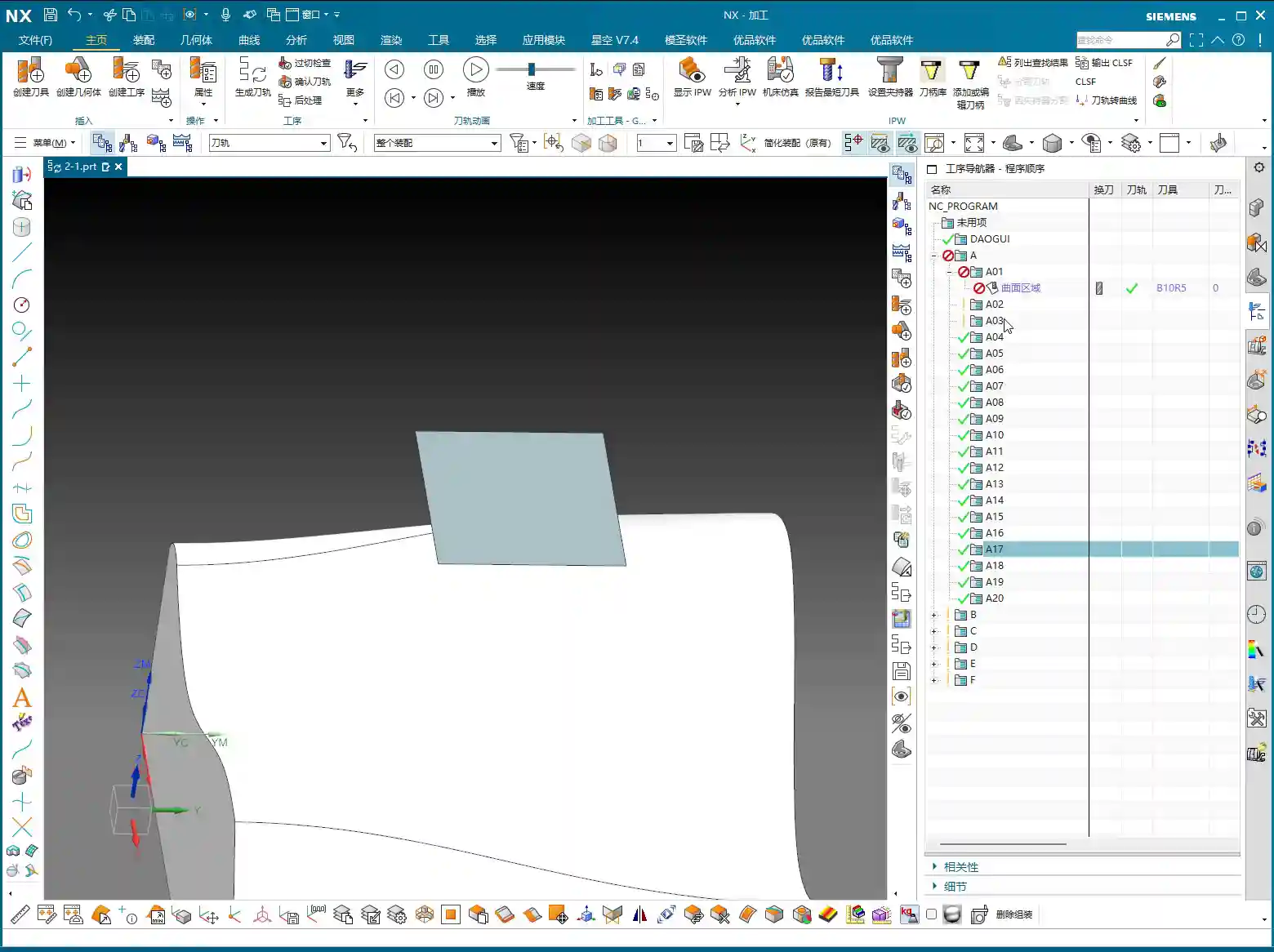
First, open Siemens NX and quickly create a simple geometric body for demonstration. Don’t always insist on specifying a part; sometimes, just selecting a face is enough to generate the program. First, select a tool—that’s standard procedure. Then, select a face as the drive surface and directly click to generate the toolpath.
Here’s the critical point! Pay close attention to the tool axis direction! Siemens NX defaults the tool axis to the Z-direction, which is usually fine. But most importantly, the arrow indicating the machining direction must align with our tool’s cutting direction, which typically needs to be outward. If the arrow points inward, isn’t that essentially “biting” into the part? At best, it’s ineffective; at worst, it causes overcutting or even tool breakage. That’s money down the drain!
And also the cutting direction (whether inside or outside the part). Whichever you select determines where the tool starts and moves. Don’t choose incorrectly, or the tool might start randomly digging into the middle of the workpiece.
Offset and Tolerance Settings
If the surface still requires stock to be left, you must input the offset parameter. Enter the exact amount of stock to be left. Don’t make assumptions here.
The tool’s positioning method, for example, “on center” or “tangent to,” is fine for flat surfaces. However, when dealing with curved surfaces, you need to be careful.
Let’s talk about the “More” settings, specifically number of passes and tolerance. Siemens NX often defaults to layering by “number of passes,” for example, 10 passes. But in actual work, we aim for accuracy, not just a certain number of passes. So, listen closely: here, you absolutely must change “number of passes” to “tolerance”! Set the inside and outside tolerances to a small value, such as ±0.005mm (approx. ±0.0002 inch) or even smaller; that’s the fundamental truth for finishing passes. For the default “More” settings, unless you’re creating a template, you generally don’t need to change them; the defaults are usually fine.

II. Overcutting and Projection Vectors: The Secret to Selecting the Part
Why Does “Overcutting” Occur?
We just ran a program, and you might have noticed that in some cases, the toolpath “overcuts,” meaning the tool moves beyond our intended machining area. Why does this happen? Because we didn’t select the part initially; we only selected a face. When Siemens NX calculates the toolpath without referencing the workpiece boundaries, the tool naturally operates without constraint.
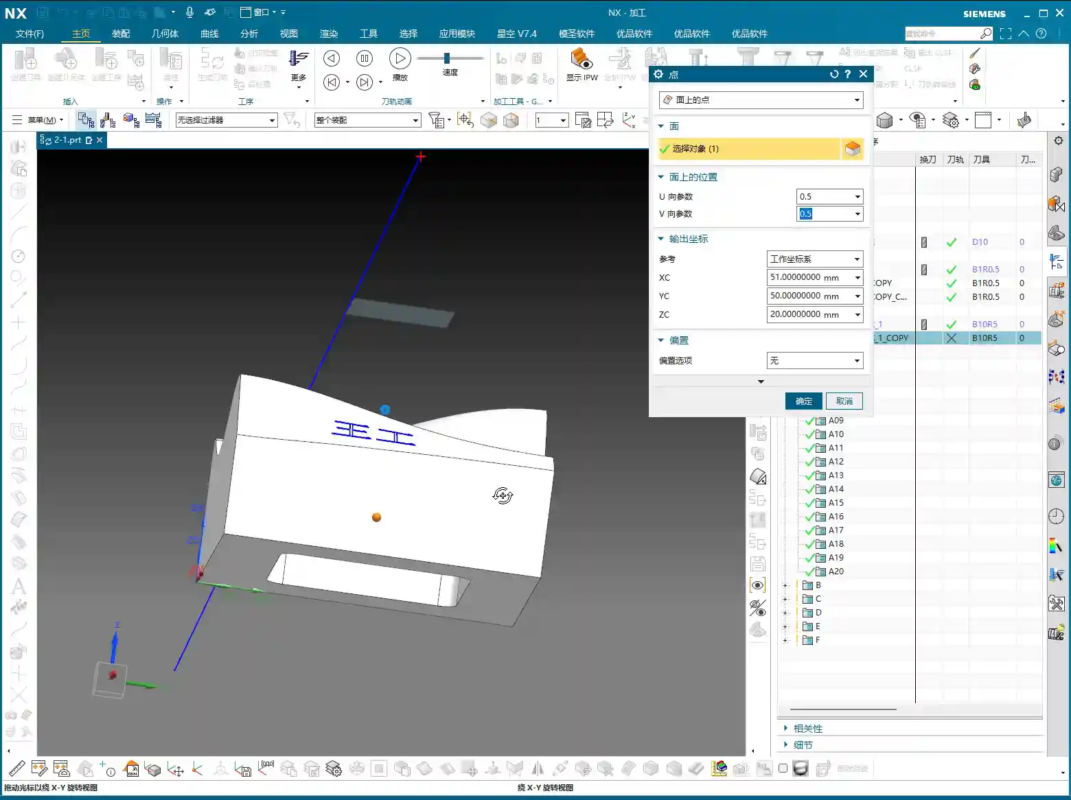
So, mark this down! Let’s generate it again, but this time, also select the part. Now, look at the toolpath—doesn’t it immediately become “tangent to” the part, with no more overcutting?

Part Selection Activates Key Parameters
This is the core concept! Once you select the part, those parameters that were previously “dormant,” such as part stock, check stock, and various collision avoidance settings, are instantly “activated”! These parameters allow Siemens NX to determine the relationship between the tool and the workpiece via projection vectors, thereby preventing overcutting and collisions. If you don’t select the part, these functions become unusable, completely wasting Siemens NX’s powerful capabilities.
Therefore, when programming Fixed-Axis Surface Drive operations, unless you explicitly know what you’re doing, always select the part to be machined so Siemens NX has a reference.
III. Stepdown (Depth of Cut) Settings: The Key to Finishing Passes

The Debate: “Stepdown” vs. “Number of Passes”
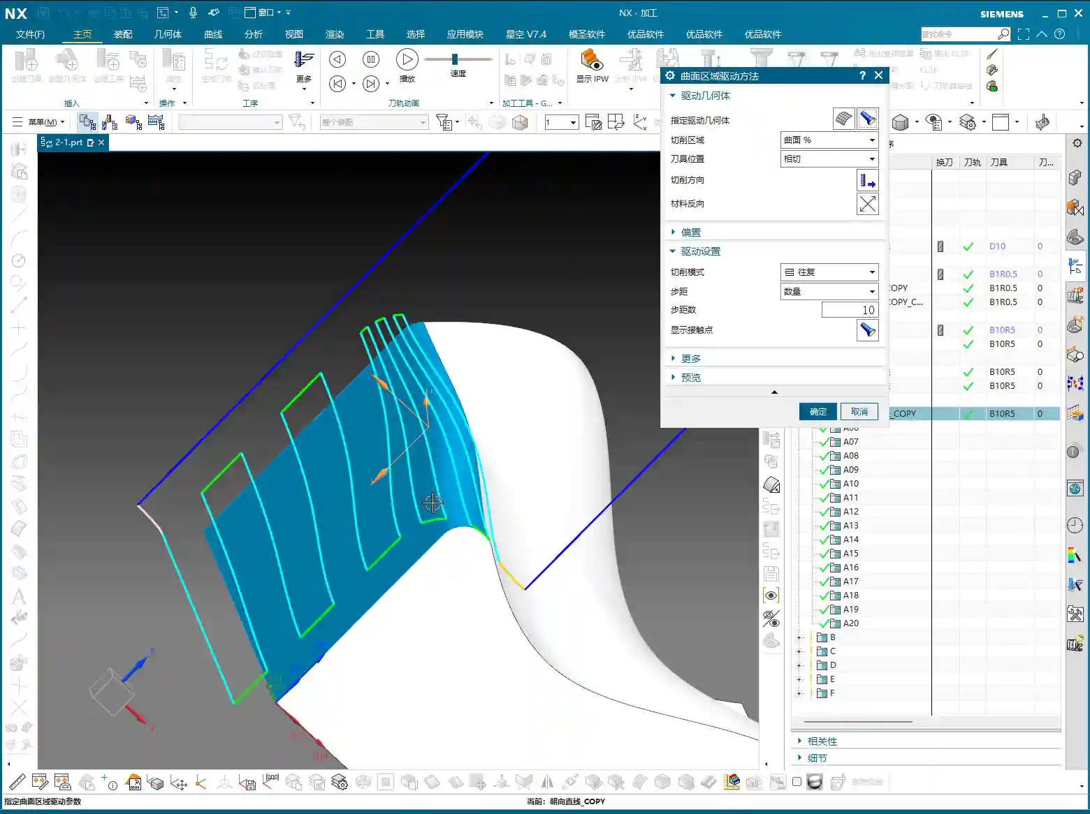
When machining surfaces, beyond just determining the number of passes, there’s an even more crucial concept: Stepdown (Depth of Cut), which is the depth of cut for each pass. If you’re not carefully calculating the total number of passes, or if you want consistent depth of cut for each pass, then don’t use “number of passes” for control; switch directly to Stepdown.
For example, if you want each pass to have a depth of cut of 1mm (approx. 0.04 inch), just input that value directly. This will result in a toolpath with uniform material removal and more easily controlled surface quality.
One important note: When you select “Stepdown” to control the depth of cut, the tool’s positioning method cannot be “on center”; it must be changed to “tangent to.” Siemens NX will display a warning, indicating that these two settings are incompatible. If your surface has both vertical and horizontal regions, using Stepdown is very convenient as it will automatically adapt.
Why Can’t We Rely on “Number of Passes” for Layering?
As mentioned earlier, if you foolishly use “number of passes” for layering, for example, dividing the entire surface into 100 passes, due to projection vector relationships, the toolpath might exhibit uneven density. In some areas, the toolpaths will be excessively dense, leading to increased tool wear and inefficient machining; in others, they’ll be sparse, making it impossible to guarantee surface quality, let alone precision.
Therefore, when dealing with complex surfaces that require a uniform depth of cut, always use “Stepdown”! This is experience gained from practical application, far more accurate than guessing or relying solely on visual inspection.

IV. Cutting Region and Surface Percentage: Precise Control of Toolpath Scope
Adjusting Cutting Start and End Points
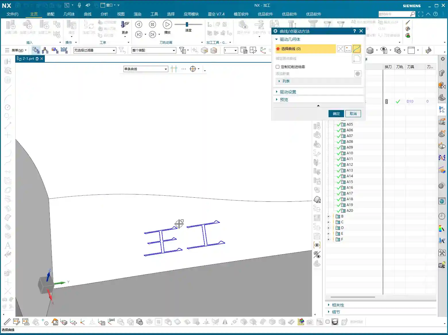
Sometimes, we don’t want the toolpath to start or end at the extremes of the surface; we need it to machine within a specific region. This is where the Cutting Region‘s Surface Percentage function comes in handy. It allows you to precisely control the toolpath’s start and end positions.
First, open “Cutting Region,” then find and click into “Surface Percentage.” You’ll find four input fields here:
- First Start Percentage: Controls the toolpath’s starting position along the first direction.
- First End Percentage: Controls the toolpath’s ending position along the first direction.
- Last Start Percentage: Controls the toolpath’s starting position along the second direction.
- Last End Percentage: Controls the toolpath’s ending position along the second direction.
How to interpret these four points? When you first click to select the “cutting direction,” Siemens NX automatically defines one corner of that surface as the “first start point.” For example, if you click on a specific corner, that corner becomes the first start point. Then, along this starting point, the first end point is defined. Similarly, another corner adjacent to the first start point becomes the “last start point,” and then the last end point is defined. These four percentages allow you to scale the cutting range between these points as a percentage.
For instance, if you set the First Start Percentage to 10% and the First End Percentage to 50%, it means the toolpath in this direction will start at 10% and end at 50%. If you then set the Last Start Percentage to 20% and the Last End Percentage to 90%, it will machine along the other direction, starting at 20% and ending at 90%. This way, you can confine the toolpath to a rectangular region.
This function is extremely useful when dealing with complex cavities or localized finishing operations, saving you a lot of extra modeling and trimming work by allowing direct control within the program.
Summary: Pitfall Avoidance Guide
- Not selecting the part is a major blunder: The most common mistake beginners make is selecting only the drive surface and not the part to be machined. This prevents Siemens NX from determining the geometric relationship between the tool and the workpiece, leading to overcutting or rendering critical parameters like part stock and check stock ineffective. Remember, unless there’s a specific reason, always select the part for surface machining!
- Layering by “Number of Passes” compromises precision: Unless you’re performing roughing with low precision requirements, avoid using “number of passes” to control cutting layers during surface finishing. Due to the effect of projection vectors, this can lead to uneven toolpath density, compromising surface quality.
- “Stepdown” and “On Center” are incompatible: When you set “Stepdown,” the tool’s positioning method must be “tangent to,” not “on center.” Otherwise, Siemens NX will throw an error or warning. This is a software logic limitation that must be respected.
- Always verify the cutting direction: After designating the drive surface each time, always observe the direction of the toolpath arrows to ensure they match your intended cutting path. If the direction is reversed, it could lead to air cuts or even incorrect machining.
- Don’t just rely on software simulation; watch the cutting sparks: No matter how realistic Siemens NX simulation is, it’s still just a simulation. During actual machine operation, cutting sparks, cutting sounds, and tool wear are all critical indicators for evaluating toolpath quality. Observe closely and summarize often—that’s the true skill of a seasoned machinist!
👤 About the Author:
The author is a veteran CNC machining professional with 15 years of industry experience, specializing in UG NX programming. This article is an original work representing personal practical insights.
⚠️ Copyright Notice: Unauthorized reproduction or distribution without prior communication is strictly prohibited.