📝 Key Takeaways:
Practical Backside Machining of Graphite Freeform Parts
Hello everyone, I’m Master Wang. Today, we’re cutting…
[VIDEO_HERE]
Hello everyone, I’m Master Wang. Today, we’re cutting straight to the chase – backside programming for graphite freeform parts. This job looks simple, but it’s full of pitfalls. In previous process classes, I briefly touched upon the overall workflow, but theory without practice is useless. Today, we’ll walk through this program step-by-step. Listen carefully, these are practical tips I’ve gained from 15 years of hands-on experience on the shop floor; you won’t find them in textbooks.
Part Characteristics and Overall Machining Strategy
Challenges and Solutions for Graphite Material
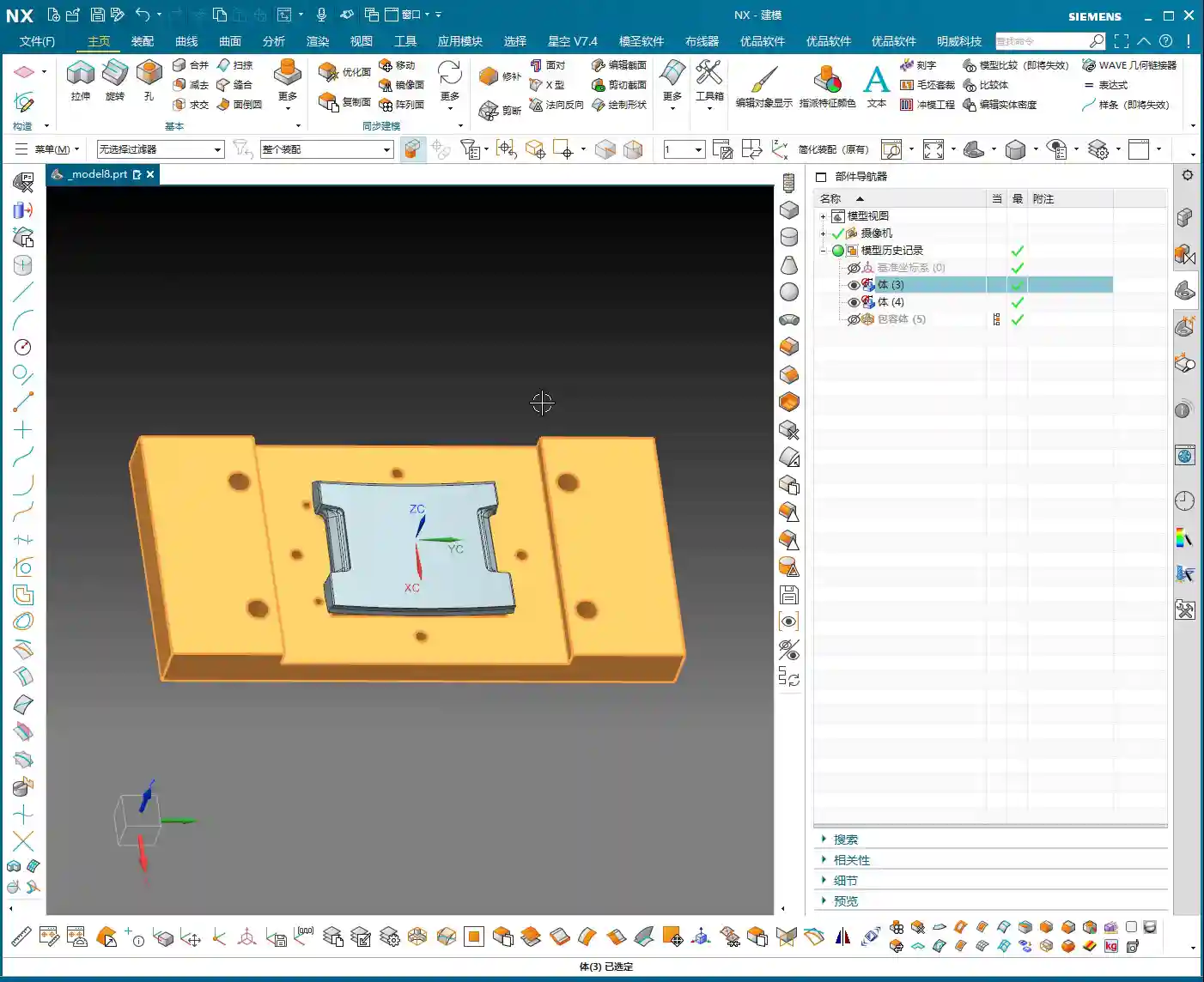
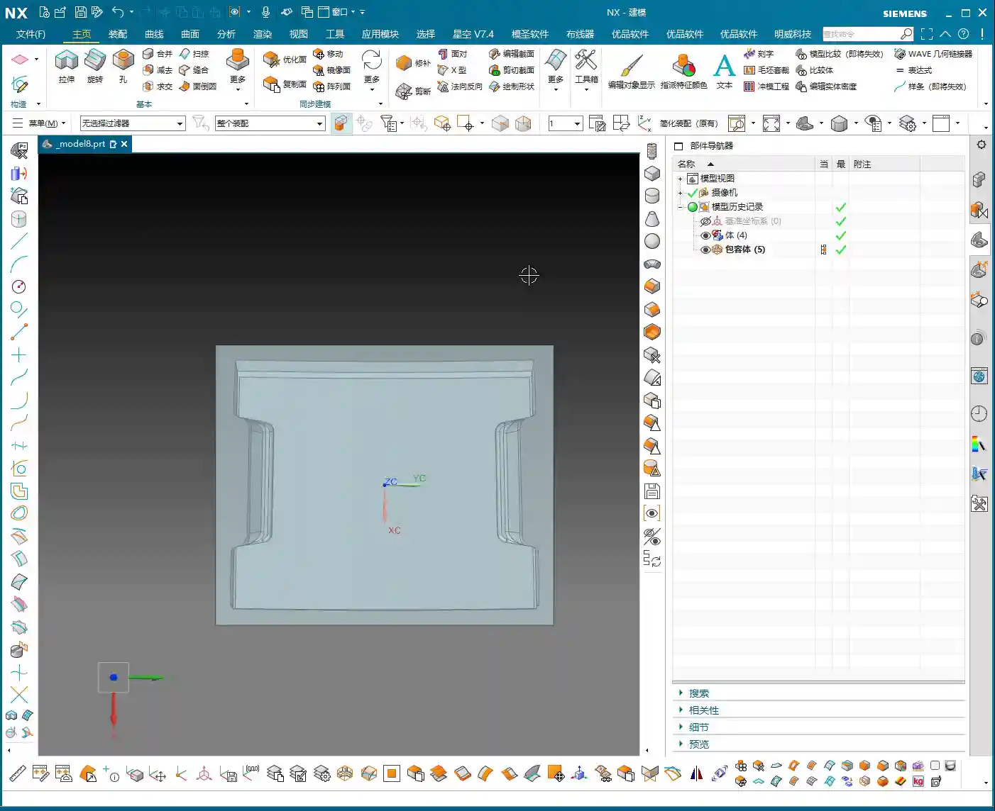
The part we’re machining is made of graphite. Graphite is brittle and prone to chipping, so cutting parameters and tool selection require special attention. This part is roughly 100×200 mm (approx. 4×8 inches) and not very thick, making it a typical freeform, complex surface part. Its difficulty lies in not having a flat datum surface like conventional parts, and it features many undercut surfaces.

The ‘Backside First’ Machining Strategy
Listen up, you can’t machine this part directly from the front side to completion. Why? Because its backside has chamfers, or rather, undercuts. If you machine from the front, you’ll either hit the tool, collide with the workpiece, or simply won’t be able to reach. Therefore, our strategy is ‘backside first’.
Step One (Backside Roughing): Start by machining the ‘backside’ of the raw material. Why start from the ‘backside’? Because the front side has complex locating features, and the backside has many undercut features. Machining the backside first allows for secure clamping/fixturing using the remaining material of the blank. Remember, during roughing, don’t machine all the way through; leave some stock, machining only about halfway. Also, rough out any other reachable areas. This ensures reliable clamping datums and material allowance for subsequent frontside machining.
Step Two (Frontside Finishing Pass): Once the backside machining is nearly complete, flip the part over. Now, the ‘backside’ we just machined serves as the locating datum surface, resting directly on our fixture.
Listen up, this is where the real skill comes in. To ensure high-precision locating at ±0.005mm, we machined locating pins into the fixture. Place the part, push it against the locating pins for a tight fit, then secure it with clamps.
With the clamps in place, first rough out the accessible areas. Then, reposition the clamps and machine the areas that were previously covered. This breaks down the entire machining process into one backside operation and two frontside operations, a total of three steps, ensuring both precision and efficiency.
Siemens NX Programming in Practice: From Raw Material to Finish Cut

Tool Selection and Strategy (Customer Specified)
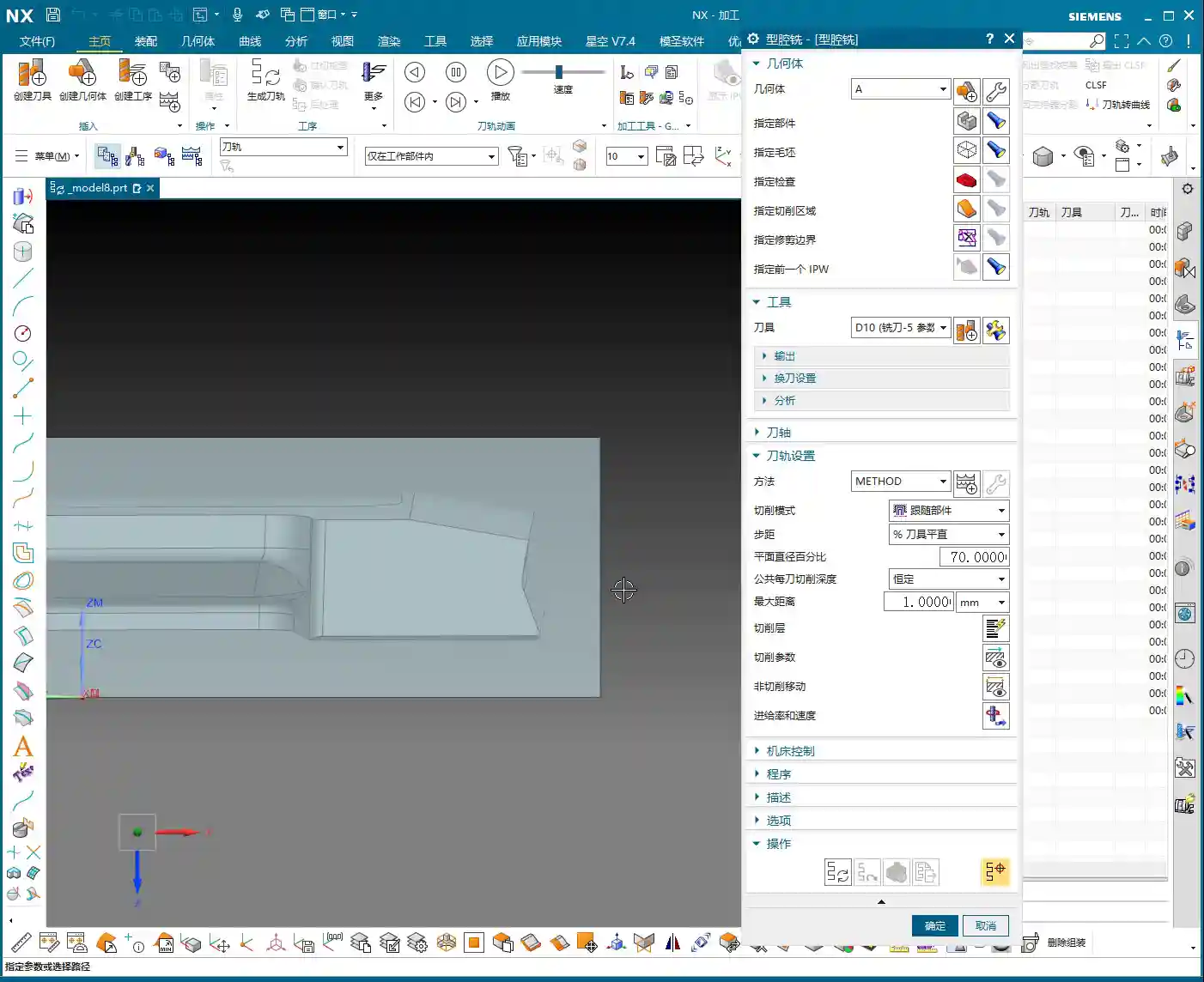
For this job, the customer supplied all the tools directly, which I really respect about their process planning. We were given three tools: one D10 flat end mill, one D6 ball end mill, and a D10 lollipop cutter specifically for undercuts.
Don’t ask me why these sizes, the customer provided them, but from a practical machining perspective, this tool configuration is quite reasonable. The D10 flat end mill handles large-area roughing, the D6 ball end mill takes care of various surface finishing passes, and the D10 lollipop cutter is the perfect tool for tackling those undercuts and deep cavities. Graphite cutting wears out tools quickly, so choosing the right tools and using them effectively saves money!
Work Coordinate System (WCS) Setup – The Foundation of Precision
Locating is the soul of machining. In Siemens NX, the Work Coordinate System (WCS) setup directly impacts machining precision. My habit is to choose a stable, easily measurable ‘bottom surface’ as the origin for complex parts like this. This way, no matter how many times you flip the part, the datum remains consistent. Today, we’ll set our WCS at the bottom surface origin.
Raw material on layer 100, fixture on layer 200 – organized and clear at a glance.

Backside Roughing: Stock Allowance is Key
Now let’s program the backside roughing operation. We’ll use the D10 flat end mill.
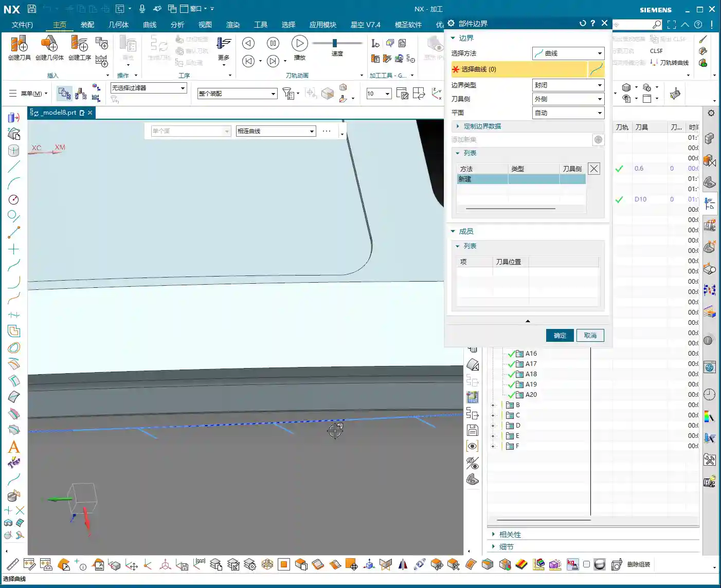
Core Point: Leave a 0.23mm machining allowance on the outer profile. This 0.23mm isn’t arbitrary; it’s an empirical value derived from repeated testing and fixture matching. Why leave it? Because when you flip the part and use the locating pins, the pins need to rest against a solid surface. If you finish to size directly, the part will wobble when the pins push against it, and precision will be impossible to guarantee! This 0.23mm is the ‘meat’ reserved for the locating pins, ensuring repeatable positioning accuracy for subsequent fixturing.
At the same time, the Depth of Cut (DOC) should not go all the way to the final bottom; lift it slightly, for example, leave 5mm stock in the Z-axis. The undercut areas at the bottom will be handled by the lollipop cutter later. This both protects the flat end mill and provides enough space for the specialized tool to intervene later.
Siemens NX’s ‘Draft Analysis’ is an excellent tool; it quickly helps you identify which surfaces are undercuts. Looking at our part, the areas visible when viewing from the backside upwards are the undercut surfaces that require special attention. Using a lollipop cutter for these undercuts is most effective and helps avoid tool collisions.
Side Wall Finish Cut: The Challenge of Complex Surfaces
After roughing the outer profile, the next step is the side wall finish cut. This is a painstaking job because almost the entire part consists of freeform surfaces, with no flat datum surfaces to work from.
Traditional ‘Planar Profile Milling’ or simply selecting surfaces for toolpaths are ineffective, and sometimes the program won’t even generate. Don’t just trust fancy software simulations; when you run it on the actual machine, sparks (graphite generates dust) will fly everywhere, and that’s a bad sign.
My approach is to use the 0.23mm stock allowance left from the previous roughing operation, combined with Siemens NX’s ‘Surface Contour Milling’. By precisely controlling boundaries and using an appropriate cutting strategy, we evenly remove the side wall stock. I won’t go into details here; I’ll demonstrate it directly in Siemens NX later so you can see my exact operations.

Summary: Pitfall Avoidance Guide
- Material Properties First: Graphite is brittle, so tool feed rate, spindle speed, and Depth of Cut (DOC) must be conservative. Err on the side of slower and shallower.
- Locating Datums are Critical: Complex parts lack ‘absolutely’ flat datums. You must learn to create datums, utilizing raw material allowance or specialized fixtures (e.g., locating pins, clamps) to ensure clamping stability and repeatable positioning accuracy.
- ‘Backside First’ Strategy: For parts with undercut features, starting the machining process from the ‘unfavorable’ backside can effectively circumvent the risks of frontside clamping interference and tool collisions.
- Stock Allowance Control is a Master Skill: Leaving a precise machining allowance (e.g., 0.23mm in this case) on critical locating surfaces is central to ensuring positioning accuracy for subsequent operations. This is practical experience rarely found in textbooks.
- Flexible Tool Selection: Facing complex surfaces and undercuts, relying on a single tool won’t work. You must skillfully use specialized tools like ball end mills and lollipop cutters. Combined with Siemens NX’s ‘Draft Analysis’ and ‘Surface Contour Milling,’ you’ll achieve more with less effort.
- WCS and Coordinate Management: Unified WCS management and layered file organization can effectively prevent machining errors caused by coordinate system confusion, improving programming efficiency.
- Trust Cutting Conditions, Not Just Simulation: Software simulation is, after all, just a simulation. During actual machining, observe the cutting conditions (e.g., graphite dust, cutting sound) and adjust parameters promptly to ensure tool and part safety.
👤 About the Author:
The author is a veteran CNC machining professional with 15 years of industry experience, specializing in UG NX programming. This article is an original work representing personal practical insights.
⚠️ Copyright Notice: Unauthorized reproduction or distribution without prior communication is strictly prohibited.