📝 Key Takeaways: Master Wang provides a hands-on guide to the core of Geometric View in UG NX machining: WCS and MCS positioning and correlation. Master practical skills for creating geometric objects, correctly setting reference coordinate systems, and safety planes to avoid common machining errors and ensure efficient and safe production.
Introduction: The Core of Coordinate Systems in Machining
Hello everyone, I’m Master Wang. Previously, we discussed creating tools in the Program View and Machine View. Those were the basics, quite straightforward. Today, let’s talk about something more critical – the Machining Coordinate System. Listen up, whether it’s 3-axis or 5-axis machining, workpiece positioning relies on it. Especially in UG (NX), it’s the “foundation” of your machining.
Distinguishing WCS from MCS
When modeling, we all know about WCS (Work Coordinate System), which is used for design. But when we get to the manufacturing module, the true core is MCS (Machine Coordinate System). Remember, MCS is the reference for our actual programming and machine execution.
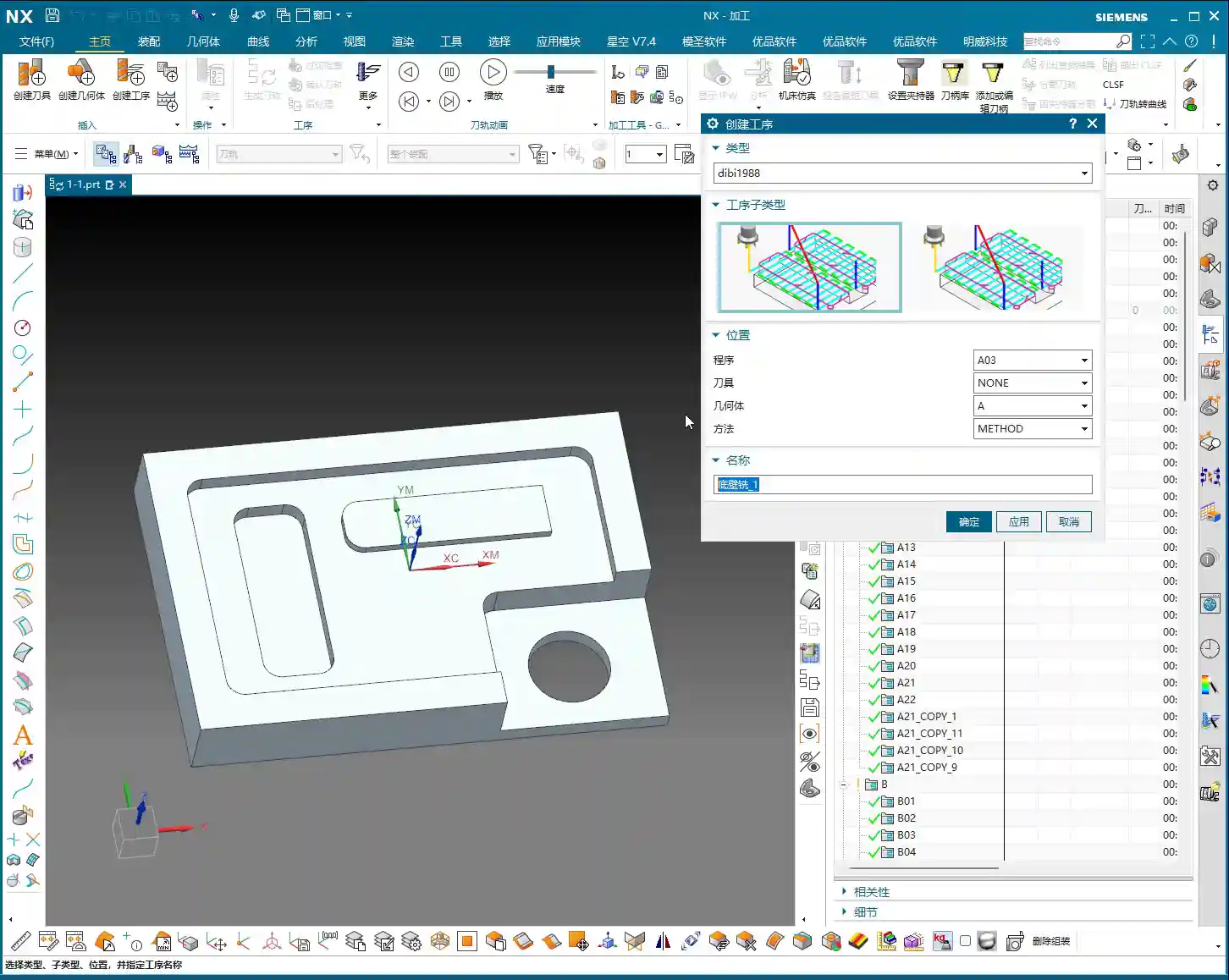
A part might have many operations, and each operation may target a different machining area. You can create countless MCSs as needed. For example, if you’re face milling this surface or machining that hole, an MCS can be set for each position.
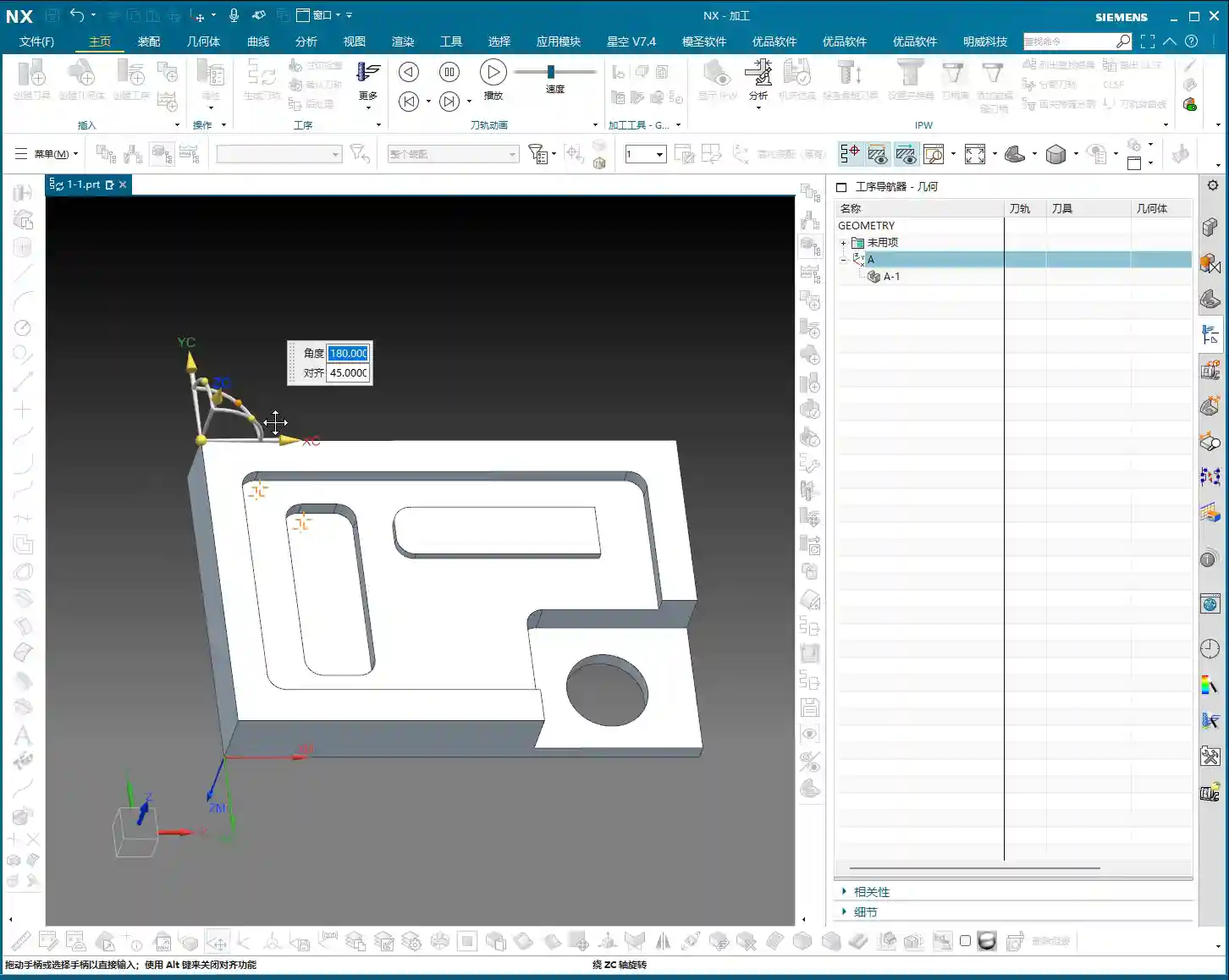
Step One: Positioning and Adjusting the WCS
To establish a reliable MCS, you first need to position your WCS (Work Coordinate System) correctly. This is the first step, and it’s fundamental. You can place it at any location you find convenient for operation, such as a corner or a face of the workpiece. There are detailed tutorials in the modeling module. Here, we’ll just click it and confirm its initial position by double-clicking or using the middle mouse button.
For instance, we place the WCS at the top-left corner of the workpiece, serving as our machining reference zero. This position must correspond to your actual clamping and tool offsetting setup.
Step Two: Creating a Geometric Object
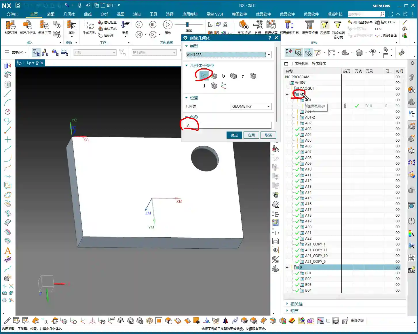
In the UG (NX) interface, after accurately positioning the WCS, the next step is to click the “Create Geometric Object” option.
Meaning and Function of Geometric Objects
The essence of “Create Geometric Object” is to create a new geometric group object within the Geometric View of the Tool Path Navigator. This geometric group acts like a container for geometric data associated with a specific MCS, such as machining features, boundaries, etc.
Typically, we use templates with pre-defined geometric objects, such as DB, 3-axis, or 5-axis templates. These pre-set geometries are convenient for quick access. When a template is loaded, it automatically switches to the pre-defined geometric object, like DB.
Selecting Geometric Object Sub-Types
Here, you’ll find sub-types like A, B, C, D, etc. Listen up, here’s a practical tip: It’s best to keep your geometric object sub-type consistent with your current program name. If your program is named “A,” then select “A” for your geometric object sub-type as well. This makes management clear and helps avoid errors.
As for other options, like those dropdown menus with small triangles, don’t worry about them for now. We’ll go into detail when we discuss specific machining processes later.
Crucial Setting: Modifying the Reference Coordinate System
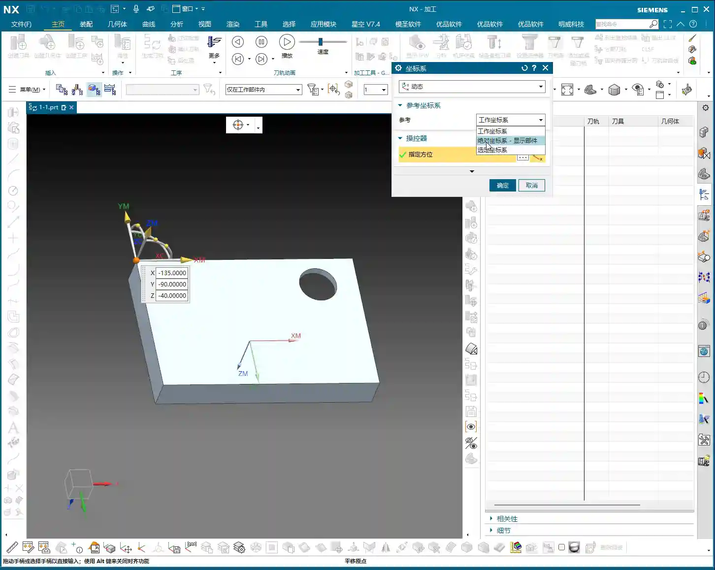
After you’ve created and confirmed the geometric object, you’ll enter the MCS dialog box. There are many options here, most of which you don’t need to touch. However, one place you absolutely must change is the “Reference Coordinate System.”
Discarding the Absolute Coordinate System, Embracing the Work Coordinate System
By default, the reference coordinate system might be the “Absolute Coordinate System.” This absolute coordinate system is the software’s own center and has no relation to our actual workpiece positioning. Therefore, we must change it to the “Work Coordinate System,” which is the WCS we set in the first step.
Remember: WCS is the coordinate system you manually place; it is where you put it. MCS, on the other hand, is what you truly need for programming, and it must reference your WCS. When these two overlap, your program will execute accurately.
Safety Settings: Plane Selection
In the MCS parameter settings, another important point is the “Automatic Plane” within “Safety Settings.”
Plane vs. Surface: A Mistake You Cannot Afford to Make
Typically, especially in 3-axis machining, we need to manually select “Automatic Plane” as “Plane.” Click it, and then specify a plane as the safety plane. Never choose a surface! If you select a surface, your tool retract and engage movements will be chaotic, which could lead to chatter or even scrapping the workpiece! We must specify a plane as a reference for the safety height, for example, a plane on top of the workpiece.
As for the numerical input that follows, like 100, that’s the height offset for your safety plane. This height is set based on your workpiece’s actual dimensions and safety requirements to ensure the tool safely retracts during non-cutting movements.
Summary: Pitfall Guide
- Coordinate System Positioning: WCS is the foundation of machining. Be sure to position it precisely according to your actual clamping setup. Don’t just rely on software simulations; look at the cutting sparks!
- Geometric Object Naming: The geometric object sub-type should preferably be consistent with the program name for clear management and to avoid confusion.
- Reference Coordinate System: The MCS reference coordinate system must be changed to “Work Coordinate System,” not “Absolute Coordinate System”! This is a common mistake for many beginners.
- Safety Plane: In “Safety Settings,” always select “Plane,” never “Surface.” Specify a safety plane and provide a reasonable safety height. This directly relates to the safe operation of the machine; get it wrong, and you’ll be experiencing tool deflection!
- Practicality First: UG (NX) has many parameters, but you don’t need to understand every single one. Grasp the core parameters, know how to use them, and use them correctly. For the rest, gain experience on the shop floor; practical experience is more important than textbooks.