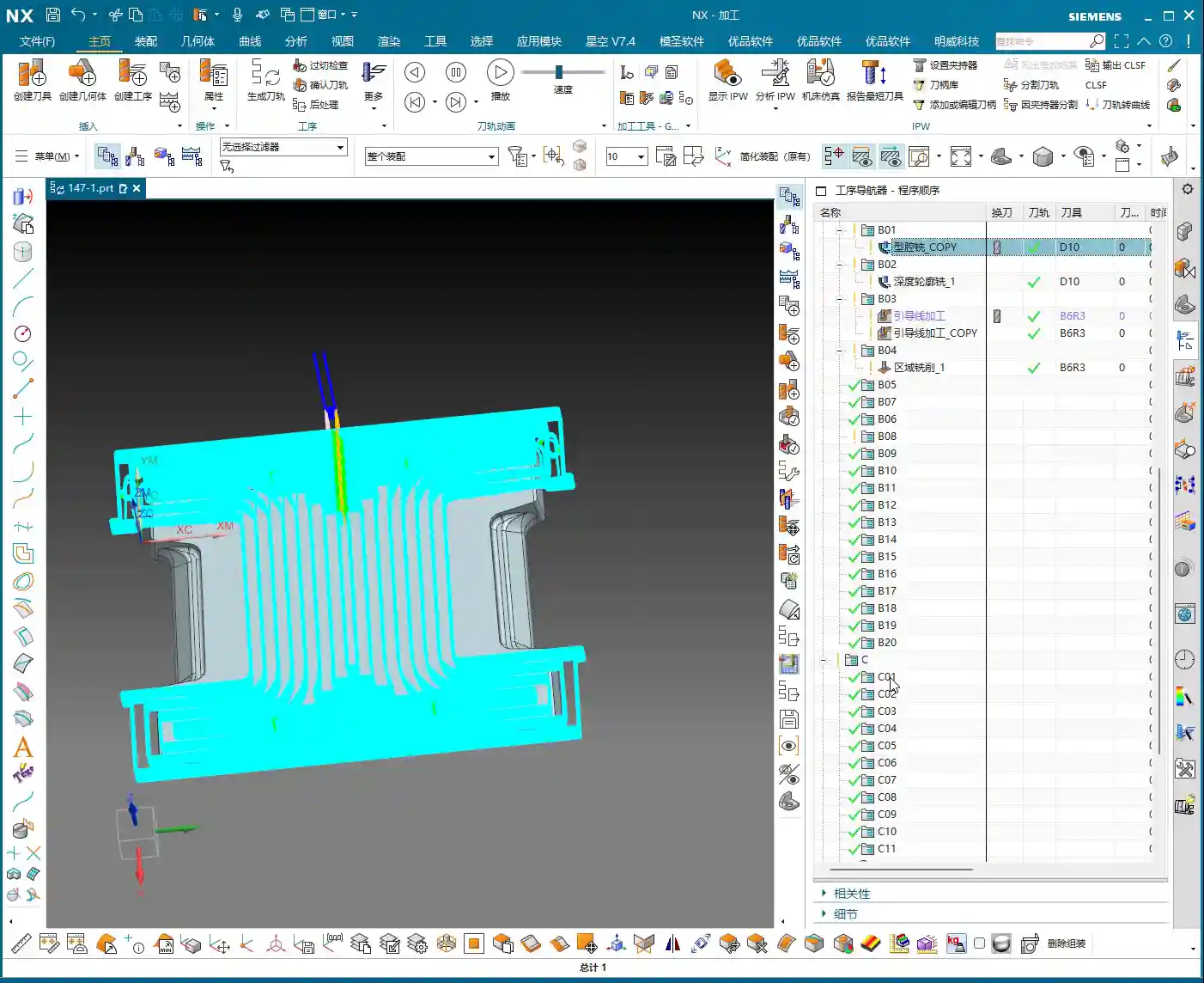
📝 Key Takeaways:
Siemens NX Expert Master Wang’s Practical Secrets: Front-Side Secondary Programming for Graphite Irregular Parts
Opening Remarks: As per tradition, let’s get straight to the practical insights!
Hello everyone, I’m Master Wang. Today, we’ll continue our discussion from last time. When it comes to front-side secondary programming for irregular graphite parts, it might look simple, but there are plenty of intricacies involved. Don’t just stare at the software interface; those seemingly insignificant small details in actual operation are what truly determine whether your product passes inspection and how efficient your process is.
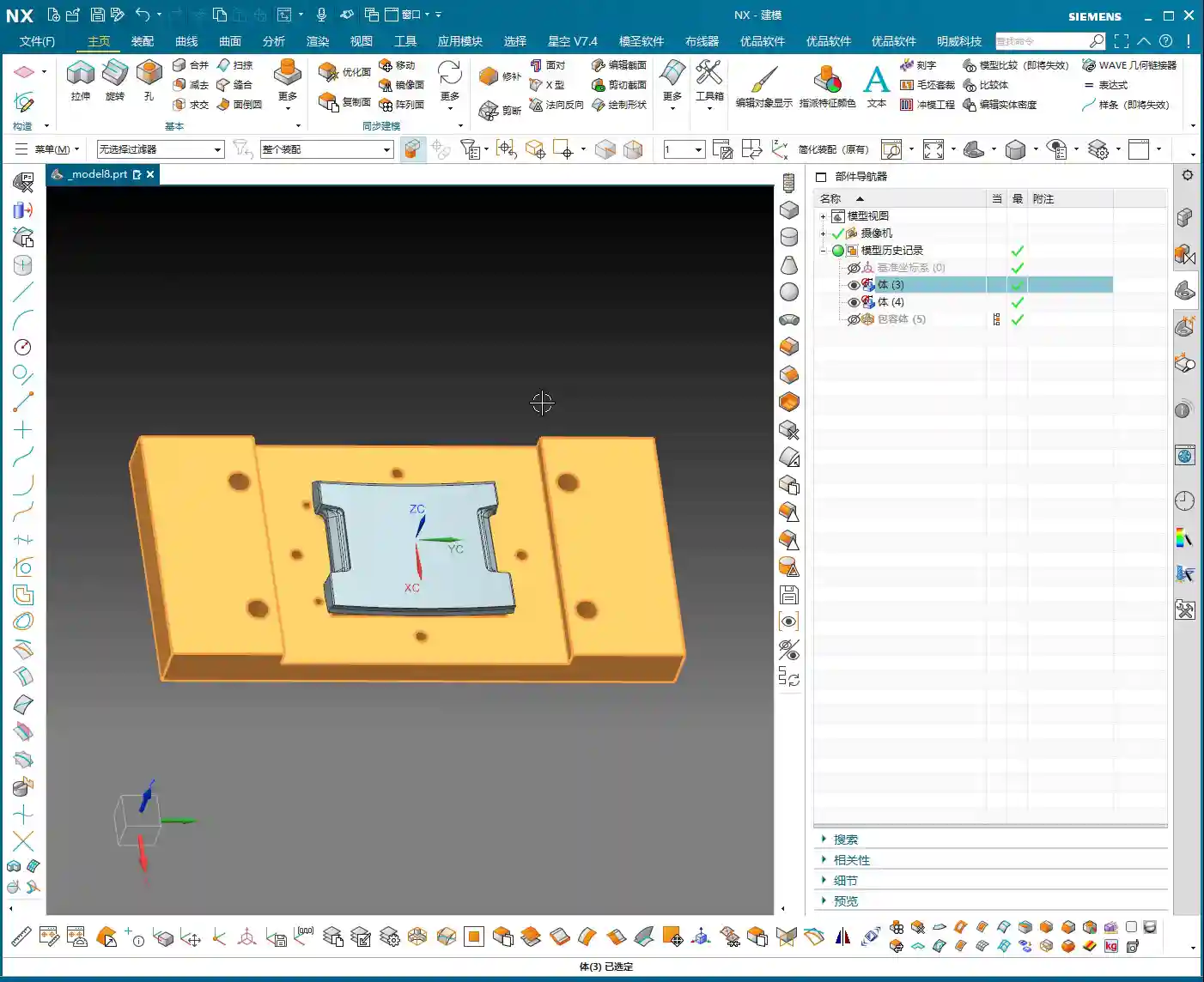
Step One: The Secrets of Clamping and Blank Selection
Clamping Plate Dimensions and Clearance – “Don’t mess around, leave some room!”
Listen up. The clamping plate we used last time might have been a bit large, and that was fine for the previous operation. But for this secondary machining, especially for the precise work on these side surfaces, you need to pay close attention to that large clamping plate.
- Actual Practice: The clamping plates we actually use are only so big; bigger isn’t always better. When fixturing, never let the clamping plate interfere with the machining area!
- Master Wang’s Insight: We’re going to use a ball end mill (or a bull nose end mill) for side Contour Milling. The tool always needs space for approach and retraction, right? So, leave just a little bit of clearance between the clamping plate and the workpiece – just a little, not too much. What do we call this? Ensure sufficient safety clearance to prevent tool collisions and overcutting. Don’t just rely on simulation software showing no collisions; that’s only theoretical. The sparks generated by the tool cutting on the actual machine are the real truth!
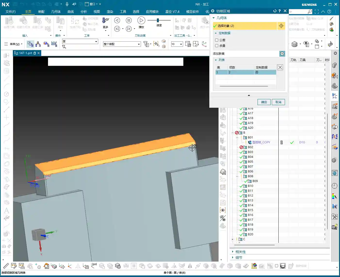
Precise Blank Selection – “Don’t select everything; be meticulous!”
Entering secondary programming, blank selection can no longer be as indiscriminate as it was for Roughing. The areas that underwent roughing have already been processed; now we only need to focus on the areas that haven’t been machined or require Finishing passes.
- NX Operation: When setting the workpiece blank, you must precisely select the portion that needs to be machined in the current operation. For areas that have already been machined, do not define them as part of the blank. For example, we only select this “0.2” stock face that needs machining.
- Master Wang’s Insight: Why do this? It’s simple: to reduce air cutting! If your blank selection is too large, the tool will spend a lot of time moving through air, wasting time and increasing machine wear. While graphite is soft, the machining time saved is pure profit! Also, clearly define the machining boundaries, such as “only machine up to this surface,” and control the Depth of Cut to prevent over-machining.

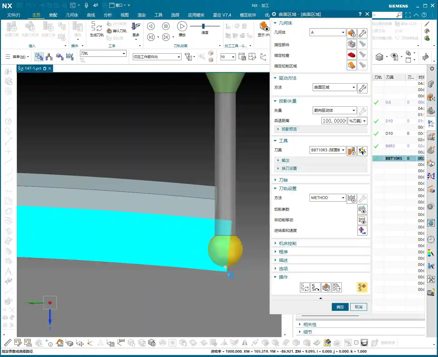
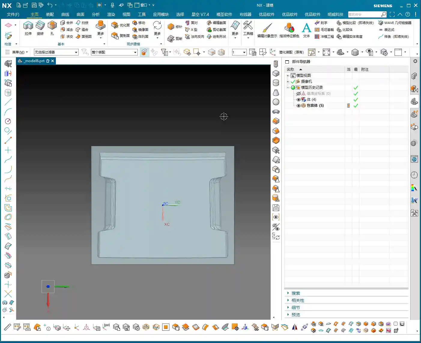
Step Two: The Core of Surface Modeling – Curve Projection and Face Splitting
For irregular graphite parts, especially complex surfaces on the front side, precise Finishing passes rely heavily on surface operations in Siemens NX. This is where mistakes often happen and where a machinist’s experience is most tested.
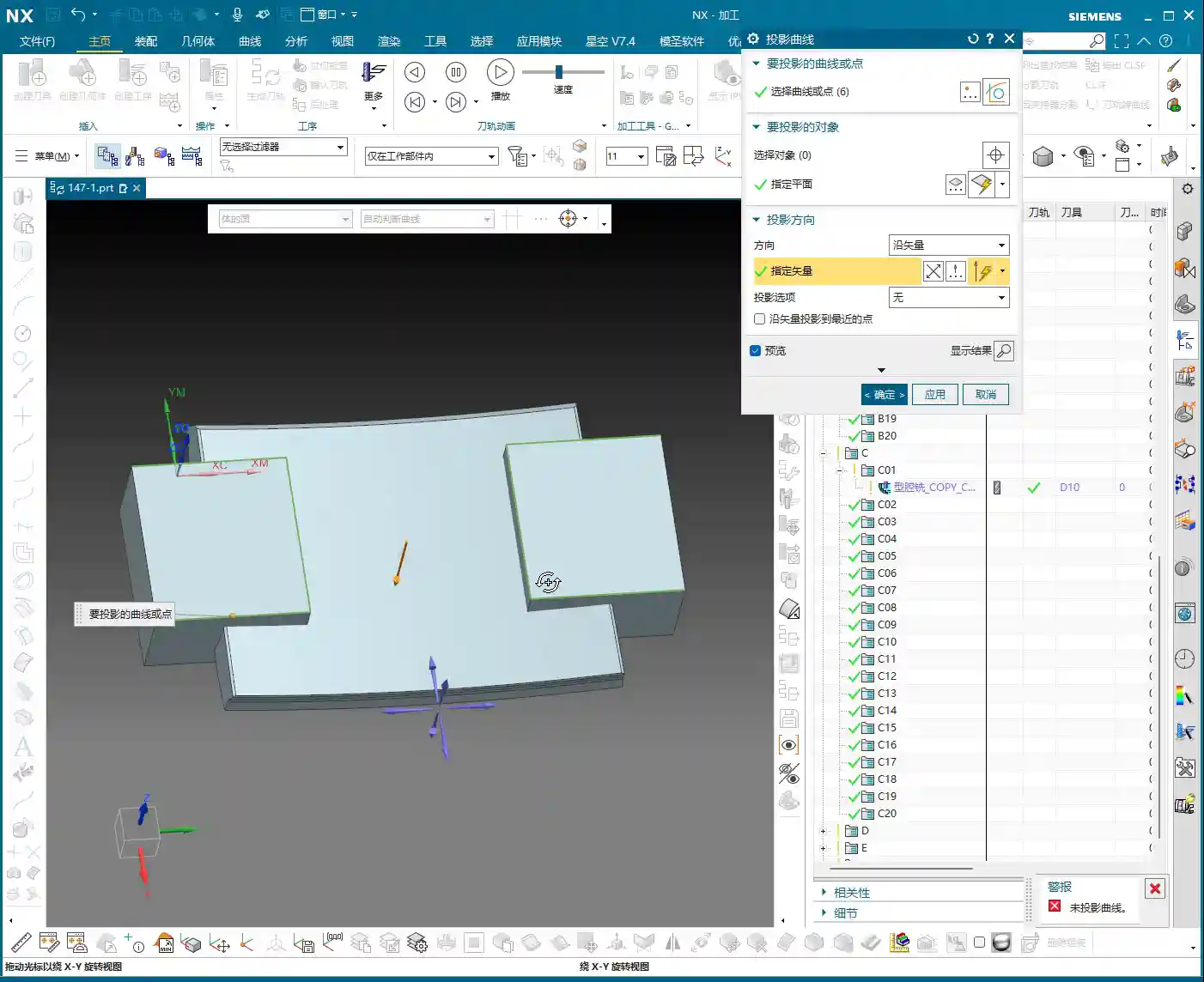
Refining Curve Projection – “Sometimes a face isn’t enough; you need the body!”
We need to machine specific side surfaces of the part, but directly selecting regions might not be precise enough. The best method is to define machining boundaries through projecting curves.
- NX Operation: First, copy the 2D curves that will serve as boundaries (e.g., the part’s edge lines) to a new layer (e.g., layer 11) for easier modification. Then, use the ‘Project Curve’ command. Here’s a pitfall: sometimes, direct projection onto a specific ‘face’ will fail. In such cases, try selecting the entire ‘body’ as the ‘projection object’! This is a common occurrence in Siemens NX; even when you intend to project onto a face, selecting the body often works.
- Master Wang’s Insight: If projection fails, don’t get frustrated right away; Siemens NX can be ‘temperamental’ sometimes. Try different projection objects, or check if your curve is complete and if the target face can truly be fully covered by the curve. Additionally, the projection direction is crucial; an “Up to Down” projection method should be determined based on the actual situation.
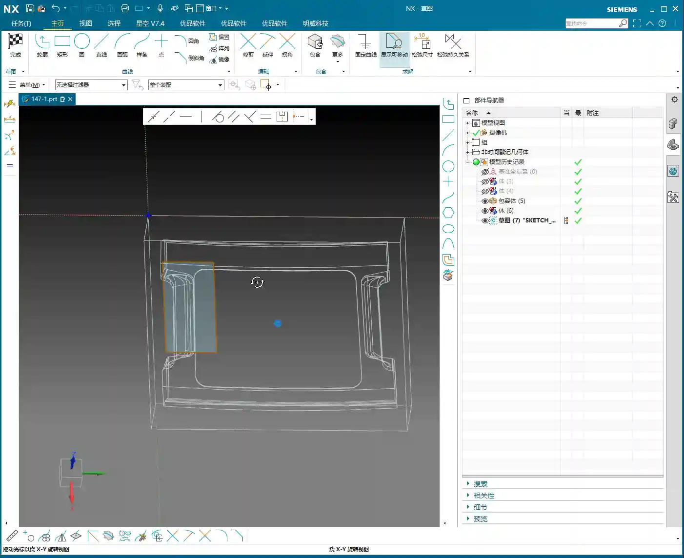
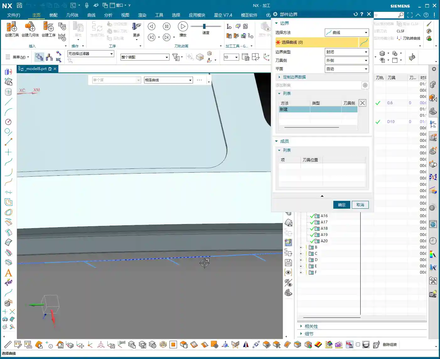
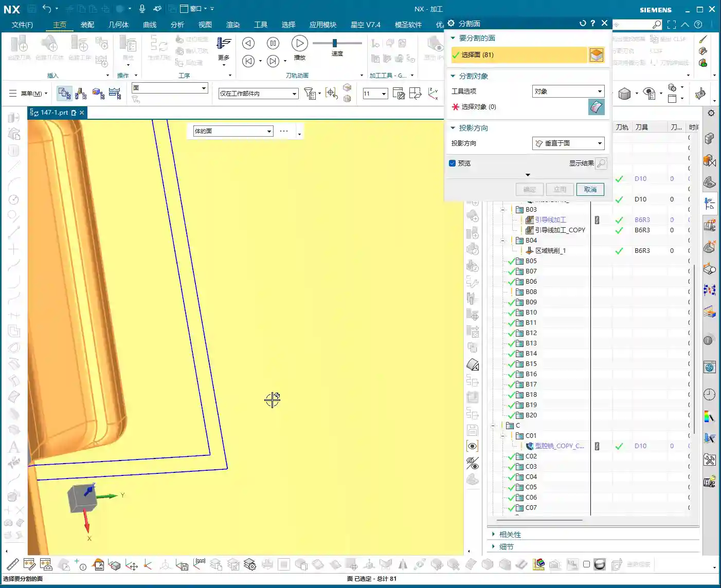
Face Splitting and Curve Offset – “Can’t split? The curve didn’t reach the edge!”
After projecting the curve, we’ll use it to split the surface, thereby defining the precise machining area.
- NX Operation: Use the ‘Split Face’ command, selecting the face to be split and the projected curve as the splitting tool. Here’s another pitfall! If your curve doesn’t fully extend to the boundary of the face, or if it doesn’t extend slightly beyond the face, it simply won’t split! In this case, you need to use the ‘Offset Curve’ command to offset the projected curve outwards, for example, set the offset amount to 3.5 mm (to ensure it encompasses the tool radius or leaves sufficient clearance), letting it ‘overshoot’ a little, then use this offset curve to split the face.
- Master Wang’s Insight: The offset value, such as 3.5 mm, isn’t arbitrary; it’s typically determined by a combination of tool radius, machining allowance, and process requirements. Offsetting ensures that the split line fully covers the machining area, preventing burrs or unmachined regions at the boundaries. Furthermore, if similar regions exist on both the left and right sides, don’t forget to use the “Mirror Plane” function to quickly duplicate curves and boost efficiency.

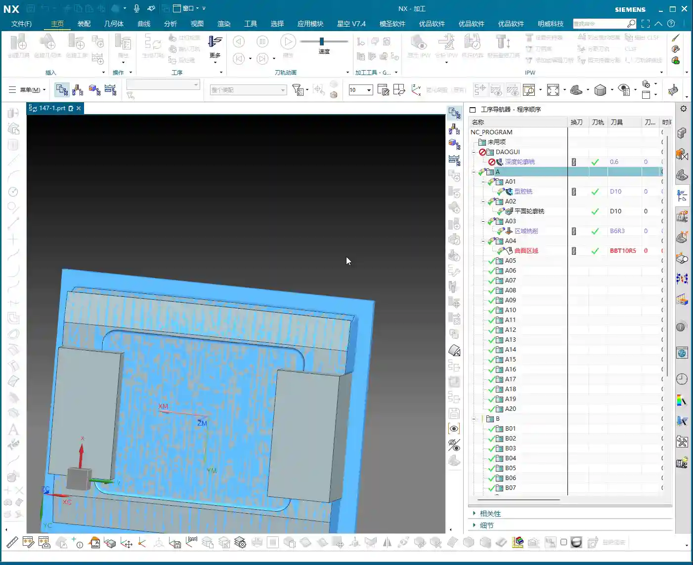
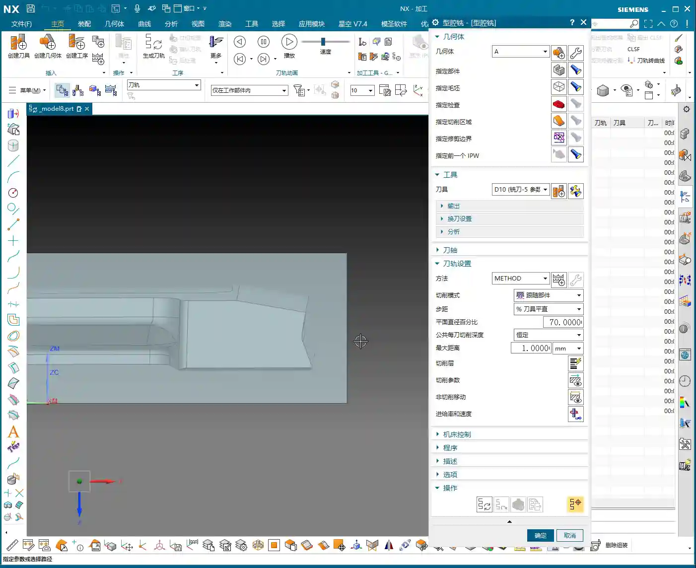
Step Three: Program Generation and Final Inspection
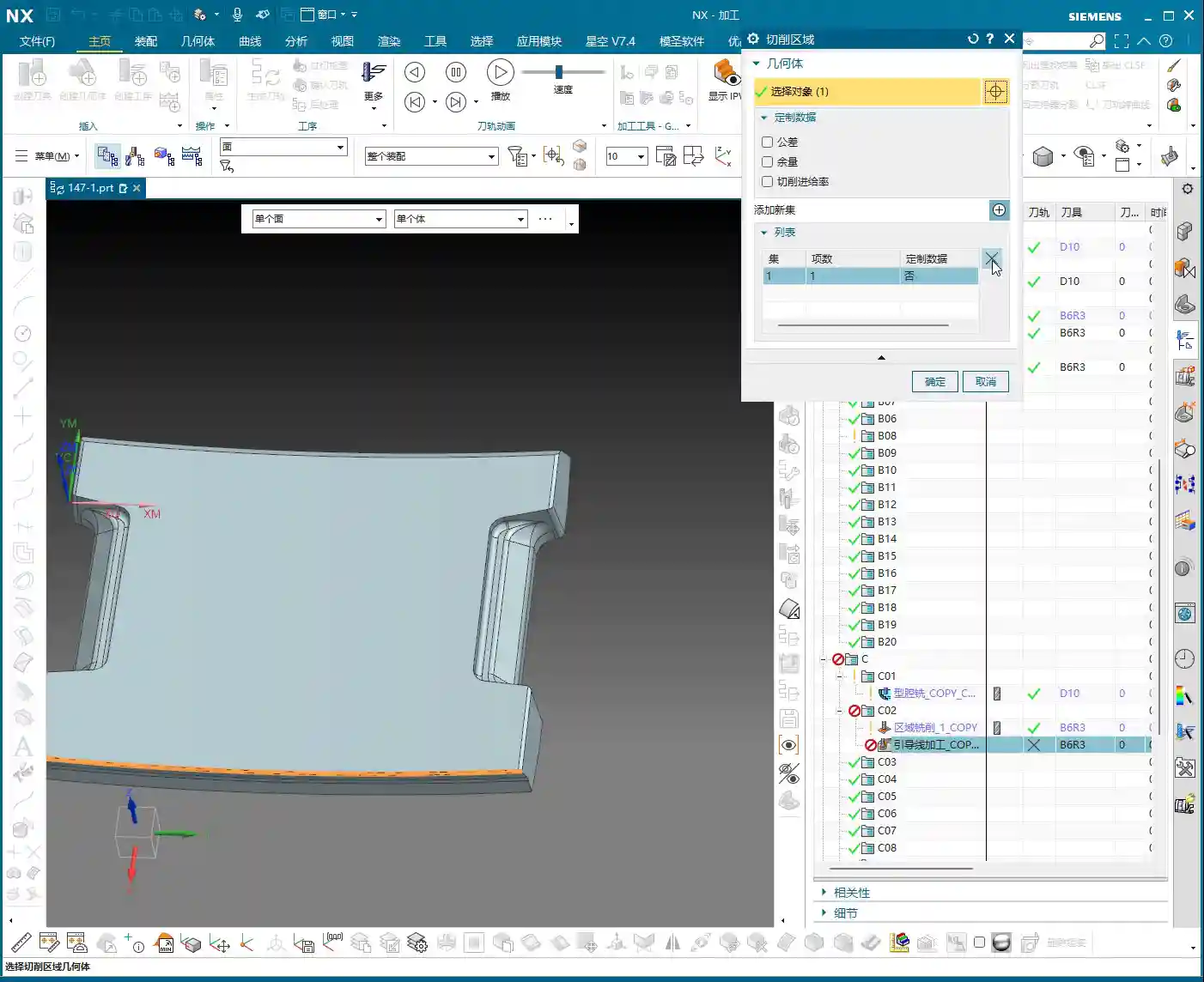
Copying Programs and Rapid Generation – “Don’t start from scratch; learn to be smart!”
Once you’ve successfully split out the machining area, programming becomes much simpler. Often, you don’t need to create a new program from scratch.
- NX Operation: Simply copy a similar, already completed program, then modify its machining area and blank definition, selecting the face we just split as the machining surface. This way, most of the cutting parameters and tool information are inherited, and you can directly generate the toolpath.
- Master Wang’s Insight: Efficiency! Efficiency! Efficiency! I’ll say it three times because it’s that important. As an experienced technician, you’re not expected to do everything from scratch, but rather to skillfully employ Siemens NX’s “Copy-Paste-Modify” technique. Especially when machining series parts or similar features, this method can significantly save programming time.
Overlap Distance and Small Chamfers – “Good enough is good enough; don’t be overly fastidious!”
After program generation, a quick inspection is essential. For some non-critical small details, you need to know when to make compromises.
- Actual Practice: When inspecting the toolpath, if you see some “overlap distance” between toolpaths, it’s generally acceptable as long as it doesn’t affect the final accuracy and surface quality. Sometimes it can even be beneficial, preventing unmachined “tool marks.” Finally, don’t forget that some small chamfers need to be addressed; these are typically completed independently with smaller tools or resolved as part of the final Finishing pass.
- Master Wang’s Insight: Machining adheres to the principle of “too much is as bad as too little.” Over-pursuing theoretical perfection can actually waste a lot of time and cost. For non-critical dimensions and non-essential surfaces, allowing a certain amount of “reasonable error” or “overlap” is practical reality. However, for materials like graphite, tool wear and the matching of cutting parameters are particularly crucial to ensure tool life and surface finish, preventing chipping.

Summary: Pitfall Avoidance Guide
1. Clamping and Workpiece:
Clamping plates must provide ample space for tool approach and retraction, especially for small tools. Re-evaluate clamping interference risks with every operation change.
2. Blank Definition:
Strictly define the blank according to the requirements of the current operation to prevent air cutting and improve efficiency. For multi-stage operations, the blank size is progressively reduced.
3. Curve Projection:
If projection to a face fails, try projecting to the entire solid (Body). The projected curve must be complete and fully cover (or slightly extend beyond) the target area, otherwise, subsequent face splitting will result in errors.
4. Face Splitting:
When splitting is unsuccessful, first check if your curve extends to the face boundary. If necessary, offset the curve (e.g., outwards by 3.5mm), letting it extend slightly beyond the face, then perform the split. This is a common technique for resolving splitting failures.
5. Programming Efficiency:
Make good use of Siemens NX’s copy-paste function to modify parameters and machining areas, rather than starting from scratch every time. For highly repetitive or similar operations, this is the ultimate time-saver.
6. Empirical Judgment:
Don’t cling rigidly to theoretical perfection. Some minor toolpath overlap or machining details in non-critical areas can be handled flexibly, provided quality is maintained. However, for critical areas involving accuracy and surface quality, meticulous attention is paramount.
Alright, that’s all for today’s practical insights. Keep observing, keep practicing, and if you have any questions, we’ll discuss them next time!

👤 About the Author:
The author is a veteran CNC machining professional with 15 years of industry experience, specializing in UG NX programming. This article is an original work representing personal practical insights.
⚠️ Copyright Notice: Unauthorized reproduction or distribution without prior communication is strictly prohibited.