📝 Key Takeaways: Engineer Wang personally shares hardcore tips for Guide Curve Cutting in Siemens NX! This tutorial will deeply analyze the decisive impact of guide curve selection on tool path direction, and demonstrate how to precisely control machining paths by adjusting guide curves or their direction parameters, avoiding air cuts and rework, thereby comprehensively improving machining efficiency and part accuracy.
Hello everyone, I’m Old Wang, Engineer Wang. Today, let’s continue our discussion on Siemens NX machining, especially the intricacies of guide curve cutting direction. You know, no matter how fancy the textbooks make it sound, nothing beats the practical experience we gain by the machine, watching the chips fly and figuring things out. Listen closely, because this directly impacts whether your tool paths run smoothly and your part accuracy remains consistent.
Guide Curve Selection: The ‘Conductor’ of Tool Path Direction
When performing guide curve cutting in Siemens NX, you must first understand a golden rule: different guide curves will result in completely different tool cutting directions and shapes. This is not a trivial matter. Selecting the wrong curve can lead the tool astray; at best, it’s an air cut; at worst, it’s a direct Depth of Cut (DOC) that scraps the workpiece.

Practical Demonstration: How to Select and Split Guide Curves
Let me demonstrate. For instance, imagine we need to machine a specific surface. First, locate the surface to be machined, then select a curve on that surface to serve as a guide curve. Sometimes, existing curves aren’t suitable, so we might need to draw our own, or split a long curve into the segments we need. Splitting is straightforward: select the curve, then select the split point or surface. The key is to be precise; don’t be vague, as it will impact your subsequent tool paths.
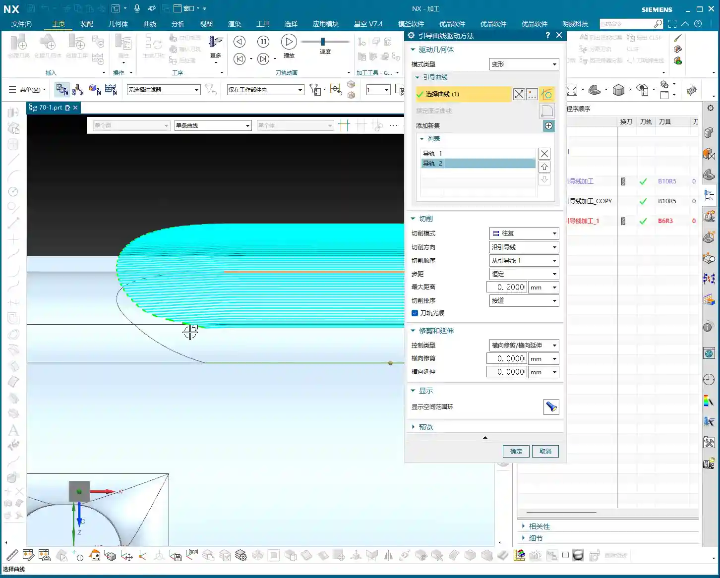
Core Concept: Two Guide Curves Define the Machining Area and Tool Path Shape
Here’s the most crucial point, where many people get confused. When we select guide curve cutting in Siemens NX, we typically need to select two guide curves, not just one. Many assume that if they select a short segment, the tool will only follow that small segment. Absolutely wrong!
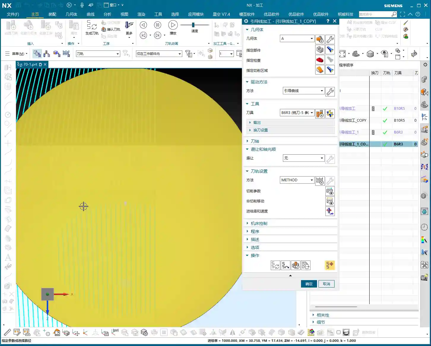
Listen up: as long as you select two guide curves, the entire region between them will be defined as the cutting area. Even if your selected guide curves are just short arcs on the surface, as long as these two curves delimit a region on your machining surface, the tool will follow the shape defined by these two guide curves within that region. This is why sometimes you might select only a small segment, yet the tool ends up traversing the entire surface. Therefore, the shape and position of the selected guide curves entirely determine the shape and machining range of the tool path.
For example, if your first guide curve is straight and the second is an arc, the tool path will transition from a straight line to an arc. If both guide curves inherently have curvature, the tool path will follow that curvature from the start. This is the essence of ‘guide curve machining’: the tool path is entirely a ‘geometric extension’ of these two guide curves.

Cutting Mode and Direction: Fine-Tuning Tool Path Control
Now that we understand how guide curves define tool path shape and range, let’s look at cutting modes and directions. These are all adjusted in the machining parameters. Don’t think it’s tedious; every step here could be key to improving your efficiency and reducing costs.

Various Cutting Modes: Choose Based on Application
- One-way: The simplest method. The tool moves across, retracts, then starts the next pass from the beginning. Suitable for simple planar or open areas; efficiency is moderate.
- Zigzag: The tool moves back and forth without retracting. Efficiency is relatively high, but be mindful of the impact on the tool and workpiece when the cutting direction changes. This is commonly used in Siemens NX.
- Zigzag Up/Down: A variation of Zigzag, specifying whether the tool lifts up or plunges down during reciprocating cuts, typically used for specific complex surface machining.
- Spiral: I need to be clear about this mode. Spiral cutting is generally for closed regions, such as a circular hole or an enclosed cavity. If you apply it to an open guide curve, while the software might calculate a tool path, it often looks messy and impractical, offering little advantage over one-way cutting. So, do not blindly experiment; for open regions, stick to one-way or zigzag.
Stepover: Determining Cutting Efficiency and Surface Finish
Stepover is the lateral distance the tool moves for each pass. This parameter is easy to understand: a larger stepover leads to faster cutting but poorer surface quality; a smaller stepover yields better surface quality but increases machining time. For roughing, you can use a slightly larger stepover; for finishing passes, you’ll need a smaller one to ensure surface finish. Naturally, setting the stepover too large can also cause uneven tool loading, or even tool breakage – these are hard-learned lessons from practical experience!
If calculations are slow, increase the stepover a bit. The software will process much faster. Once the direction and mode are confirmed, adjust back to the actual stepover. That’s a little trick for you.
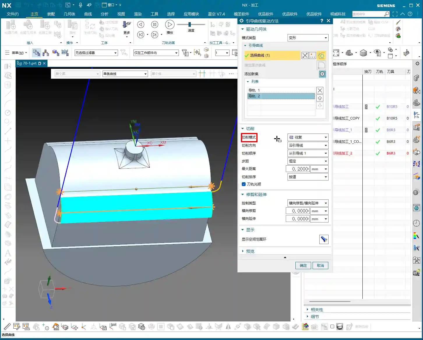

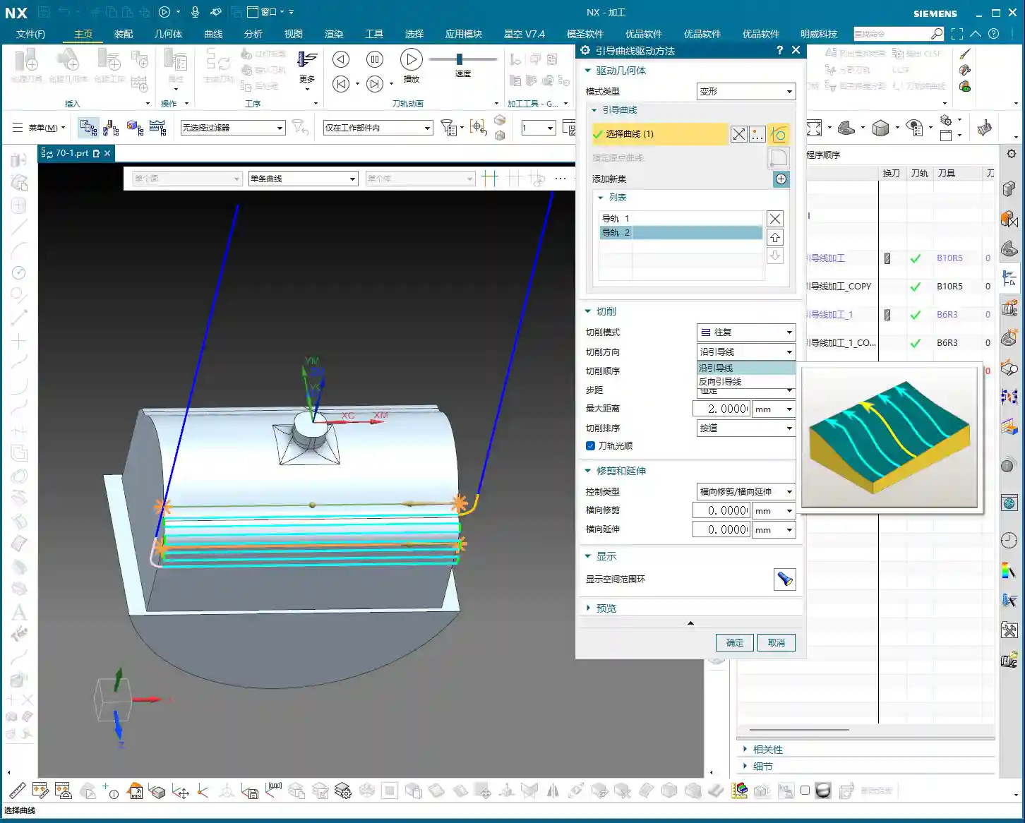
Cutting Direction: Along Guide Curve vs. Reverse Guide Curve
This is the most critical part of today’s discussion!
- Along Guide Curve: As the name suggests, the tool will start cutting along the direction you chose for the first guide curve. Siemens NX automatically identifies the start point and direction when you select the curve, displaying it with an arrow in the software. Use this option if you want the tool to engage from a specific direction and follow your chosen path.
- Reverse Guide Curve: This option will reverse the direction you chose for the first guide curve. In other words, if ‘Along Guide Curve’ cuts from left to right, ‘Reverse Guide Curve’ will make it cut from right to left. The arrow direction will be completely opposite.
Here’s a very important practical tip: Although the ‘Reverse Guide Curve’ option exists, we don’t commonly use it in actual machining. Why? Because often, if you want to change the direction, you can simply re-select your guide curve, starting from the end where you want the tool to begin cutting, and the direction will be naturally set. This is more intuitive and less prone to errors. Remember, when selecting a guide curve, the small arrow displayed represents the tool’s starting direction. Whichever end of the curve you select as your ‘starting point’, that’s where the tool will begin its first pass.
Summary: Pitfall Avoidance Guide
Core Pain Points and Solutions
1. Misconception: Guide curves only define local paths.
Reality: Two guide curves jointly define the entire machining area and tool path shape. Even if your selected curves are short, any area within the bounds of the two guide curves will be machined.
To Avoid: When planning guide curves, consider the overall region between them, not just individual curve segments.
2. Misconception: Spiral cutting is universally applicable.
Reality: Spiral cutting is primarily suitable for closed regions. Using it in open areas often yields suboptimal results, or is even indistinguishable from one-way cutting.
To Avoid: Choose the cutting mode based on the enclosure of the machining area. For open regions, prioritize one-way or zigzag to avoid wasting computational resources and time.
3. Misconception: Relying on the “Reverse Guide Curve” button.
Reality: Siemens NX’s “Reverse Guide Curve” can change direction, but in practice, it’s more recommended to control direction directly by re-selecting the starting end of the guide curve.
To Avoid: Develop good habits. Determine the direction when first selecting the guide curve, pay attention to the small arrow, and avoid secondary modifications or unnecessary hassle. This is like giving instructions to a machinist: the clearer, the better.
Alright, that’s it for today’s valuable insights. Practice more in the software, observe more at the machine, and communicate with experienced machinists. Only then can these ‘unwritten rules’ truly become your own expertise.
Thank you for watching. We’ll continue our discussion next time.
👤 About the Author:
The author is a veteran CNC machining professional with 15 years of industry experience, specializing in UG NX programming. This article is an original work representing personal practical insights.
⚠️ Copyright Notice: Unauthorized reproduction or distribution without prior communication is strictly prohibited.