📝 Key Takeaways: Master Wang’s In-depth Explanation of Siemens NX Constant Offset Machining: A deep dive into “Left, Right, Both Sides” guide curve offsets and the practical application of “Towards” and “Away From” guide curves. This guide emphasizes how to distinguish left and right sides by the guide curve’s arrow direction and select appropriate tool path strategies for Roughing and Finishing pass scenarios. It avoids theoretical detachment, focuses on actual machine operation and cost efficiency, helping you overcome NX programming blind spots.
Master Wang Speaks: Master Constant Offset to Double Your Machining Efficiency!
Hello everyone, I’m Master Wang. Today, we’ll continue discussing machining programming in NX. Last time, we covered the “Morph” pattern; today, we’ll delve into another commonly used pattern that often confuses younger engineers—Fixed Guide Constant Offset. Listen up: master this, and you’ll eliminate countless unnecessary tool movements, boosting your efficiency significantly—it’s not just a small improvement! Don’t just get dazzled by fancy software simulations; when the machine is running, the cutting sparks tell the real story!
Constant Offset: Precisely Controlling Machining Boundaries
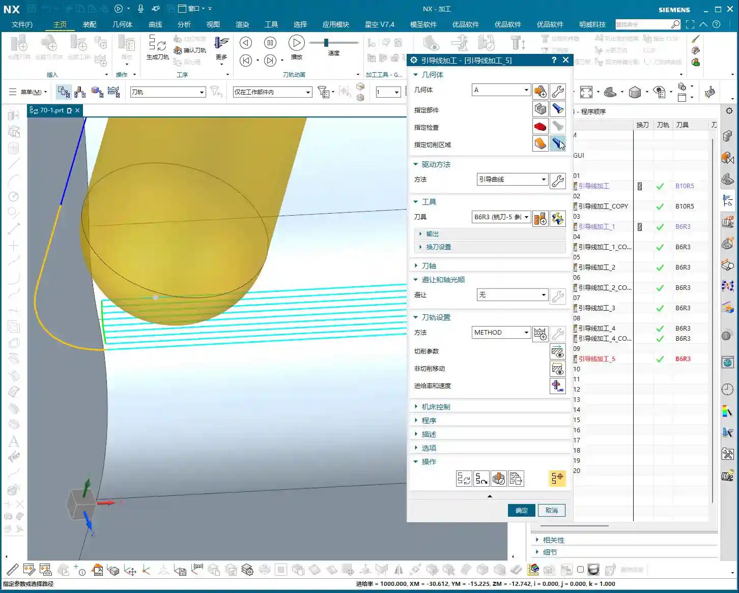
The “Constant Offset” pattern, as the name implies, makes the tool path follow your selected guide curve, maintaining a fixed offset during machining. This is particularly useful for machining cavities and surface contours. However, there’s a lot to this, with three offset directions: Left, Right, and Both Sides. It’s like cutting a slot on a milling machine—whether the tool runs on the left side, the right side, or in the middle of the slot, the principle is the same.
- Left Offset: The tool machines on the “left side” of the guide curve. Which side exactly? Don’t worry, I’ll show you how to determine it later. Choosing “Left” typically means the guide curve acts as your right boundary, with the tool path expanding to the left of the guide curve.
- Right Offset: Conversely, the tool machines on the “right side” of the guide curve. The guide curve becomes your left boundary, and the tool path extends to the right of the guide curve.
- Both Sides Offset: As the name implies, the tool machines on both sides of the guide curve. This is commonly used to remove material from both sides of the guide curve or when the guide curve itself represents a centerline.
Master Wang’s Tip: After selecting a guide curve, the software will display an arrow indicating its direction. Remember, when you face the guide curve with the arrow pointing forward, your left hand side is “Left,” and your right hand side is “Right.” This is the simplest and most practical way to determine it—a thousand times better than memorizing concepts!

Towards Guide Curve: Convergent Finishing Pass
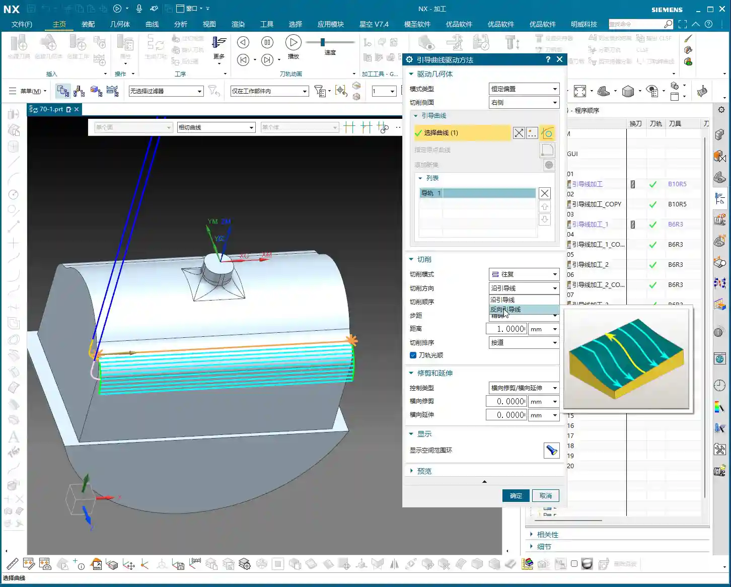
Now let’s talk about “Towards Guide Curve.” Change this parameter, and the tool path changes significantly.
Selecting “Towards Guide Curve” means your tool will gradually approach and cut from the outside of the machining area towards the guide curve. The guide curve serves as the final machining target.
Practical Application:
Imagine, for example, you need to perform a Finishing pass on a surface where the guide curve is the surface’s centerline or a feature line. Using “Towards Guide Curve,” the tool path will move like ripples, converging inward from the outside, eventually meeting the guide curve. This method is highly suitable for Finishing pass because it ensures superior surface quality, cleans up residual material more effectively, and minimizes issues with tool path overlap marks. Especially when Face Milling complex surfaces like mold cavities or blades, using this for the final trim delivers excellent results!

Away From Guide Curve: Diffusive Roughing
The opposite of “Towards Guide Curve” is “Away From Guide Curve.”
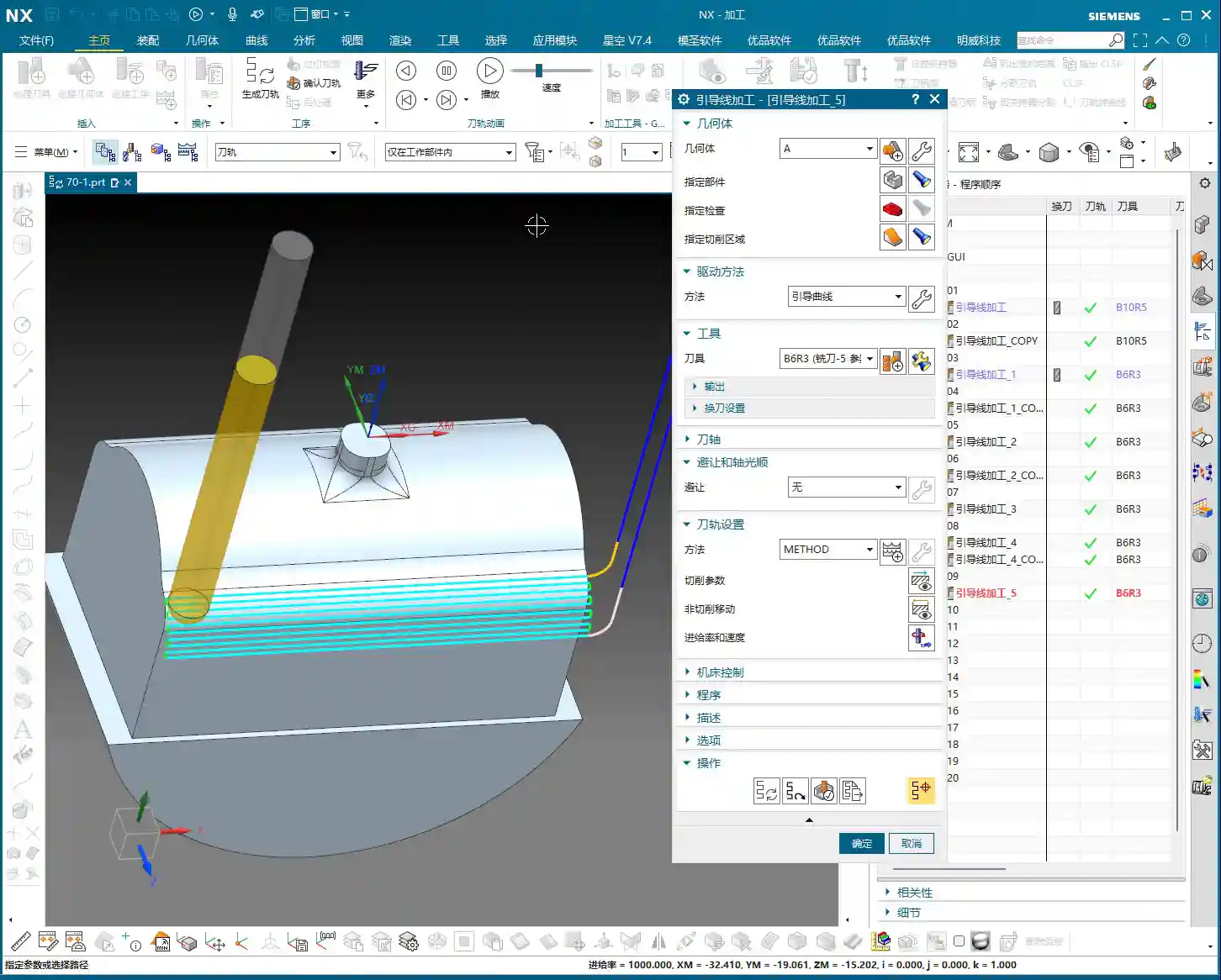
When you select “Away From Guide Curve,” the tool starts from your selected guide curve and diffuses outwards into the machining area. It uses the guide curve as its starting point and gradually expands outwards.
Practical Application:
This method is more suitable for Roughing or machining open areas. For example, if you need to Face Mill a large flat area outwards starting from a pre-drilled hole, or clear the bottom of a deep slot where the guide curve defines the slot bottom’s contour. The tool starts cutting from the guide curve, expanding outwards layer by layer, which effectively avoids the risk of plunging directly into solid material and reduces cutting force impact. Especially when machining high-hardness materials like titanium alloys or high-temperature nickel-based superalloys, this method allows for better control of cutting load and extends tool life.

Plunge Direction and Cutting Order: Inside-Out and Outside-In
Beyond offset direction, we also need to pay attention to the plunge direction and cutting order, as these significantly impact machining quality and efficiency.
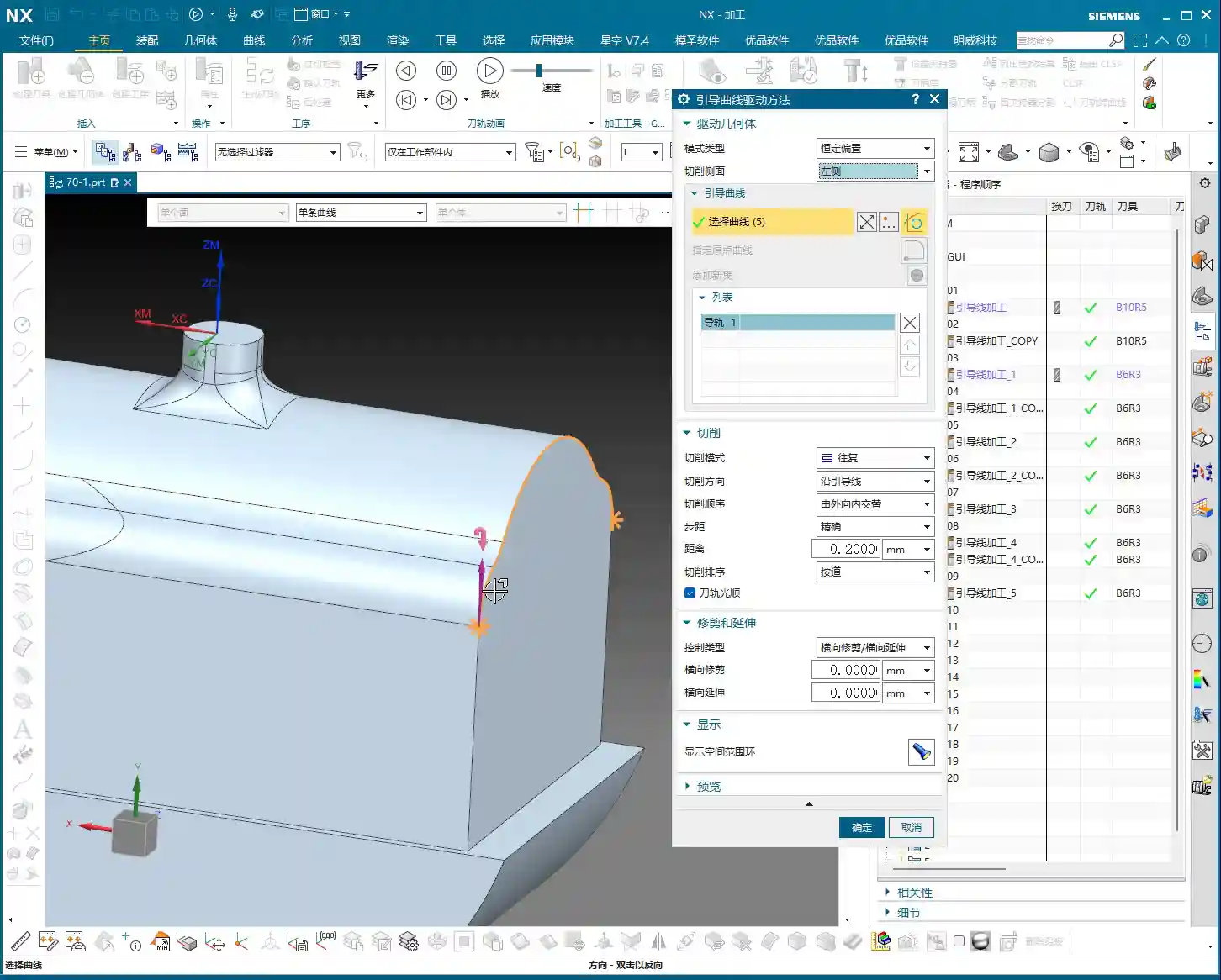
- Outside-In (Alternate): This means starting from the outer perimeter of the machining area and moving inward in concentric passes. It’s suitable for most cavity machining operations, allowing for effective chip evacuation and preventing chip buildup.
- Inside-Out (Alternate): The tool starts from the center or inner side of the machining area and gradually expands outwards. This method can be exceptionally effective in specific situations, such as when you need to prioritize the machining quality of the central area, or when the tool needs to start cutting within a deep hole.
There are also “Along Guide” and “Reverse Guide” options, which determine whether your tool path follows the guide curve’s direction or goes against it. This impacts your conventional and climb milling strategies, subsequently affecting surface finish and tool wear.

How to Distinguish Left from Right? Look Here!
Many engineers get confused by “Left” and “Right” sides when they first start. In NX, when you select a guide curve, the software automatically displays a white arrow. This arrow is your guide!
The Simple, Direct Method:
- Click on your guide curve with the mouse; the arrow will appear.
- Imagine yourself as the tool, moving along the direction of the arrow.
- Your left hand side is “Left,” and your right hand side is “Right.”
It’s that simple! If you’re ever unsure, rotate the model to an angle where you are aligned with the arrow’s direction, and it will become immediately clear. This little trick will save you a lot of headaches and prevent scrapped parts!
Master Wang’s Practical Secrets: Parameter Interplay and Pattern Selection
Although “Constant Offset” and “Morph” patterns appear to have many similar parameters, their underlying logic and application scenarios are distinct. “Constant Offset” focuses more on the offset strategy from a single guide curve, whereas “Morph” performs surface interpolation between two or more guide curves. Therefore, when you intend to use functions like “Towards/Away From Guide Curve,” ensure you select the “Fixed Guide Constant Offset” pattern. In the “Morph” pattern, you won’t find these options, as it operates on its own “start guide to end guide” logic.
Furthermore, layout options like “Exact” are similar to “by tool” or “by region” concepts, all controlling the distribution of the tool path within a specified area. Most of the time, these options will automatically match your machining objectives. But remember one thing: any software option must ultimately align with actual machining requirements. Don’t use a flashy feature just for the sake of it; evaluate whether it genuinely helps you improve efficiency, reduce costs, and ensure quality.
Summary: Pitfall Avoidance Guide
- Differentiate Machining Patterns: “Constant Offset” and “Morph” are two entirely different machining patterns. When dealing with “Towards” or “Away From” guide curve functions, always select the “Fixed Guide Constant Offset” pattern. Don’t waste time searching for them in “Morph”; you won’t find them there, and you’ll just lose time.
- Determine Left/Right by Arrow: The left and right sides of a guide curve are not fixed but determined by the guide curve’s direction arrow. Imagine yourself as the tool, moving along the arrow’s direction; your left hand side is the “Left” side, and your right hand side is the “Right” side. This is fundamental knowledge that you must master.
- Choosing “Towards” vs. “Away From”:
- “Towards Guide Curve”: Primarily used for Finishing pass, converging from outside-in to improve surface quality.
- “Away From Guide Curve”: Primarily used for Roughing, diffusing from inside-out, which aids chip evacuation and reduces initial cutting impact.
Choose flexibly based on your machining stage (Roughing, semi-Finishing pass, Finishing pass) and material properties.
- Tool Path Simulation Isn’t Everything: No matter how good software simulation looks, it’s just a theoretical representation. During actual machining, pay attention to cutting sparks, chip evacuation, tool sound, and workpiece surface quality; these are the true benchmarks for determining if a tool path is effective. Don’t just stare at the screen; learn to “read the sparks, listen to the sounds, and feel the remaining material.”
- Consider Material Properties: For instance, when machining sticky aluminum, pay attention to chip evacuation. When machining hard and brittle hardened steel, prevent chipping. When machining nickel-based alloys, cutting forces are high, so ensure sufficient rigidity and low cutting speeds. For different materials, your offset amount, feed rate, and spindle speed must be adjusted accordingly.
Alright, that’s all for today. There are many intricacies to NX programming; what you learn from books is just a theoretical framework. What truly solves problems and boosts efficiency comes from hands-on experience gained at the machine, step by step. Next time, if we get the chance, we’ll discuss how to further optimize tool paths through post-processor modifications, turning your CNC machine into a real profit-making tool!
[/CONTENT]
[EXCERPT]
Master Wang’s In-depth Explanation of Siemens NX Constant Offset Machining: A deep dive into “Left, Right, Both Sides” guide curve offsets and the practical application of “Towards” and “Away From” guide curves. This guide emphasizes how to distinguish left and right sides by the guide curve’s arrow direction and select appropriate tool path strategies for Roughing and Finishing pass scenarios. It avoids theoretical detachment, focuses on actual machine operation and cost efficiency, helping you overcome NX programming blind spots.
👤 About the Author:
The author is a veteran CNC machining professional with 15 years of industry experience, specializing in UG NX programming. This article is an original work representing personal practical insights.
⚠️ Copyright Notice: Unauthorized reproduction or distribution without prior communication is strictly prohibited.