👤 About the Author: The author is a veteran CNC machining professional with 15 years of industry experience, specializing in UG NX programming. This article is an original work representing personal practical insights.
⚠️ Copyright Notice: Unauthorized reproduction or distribution without prior communication is strictly prohibited.
📝 Key Takeaways: Master Wang provides an in-depth analysis of practical Siemens NX hole milling techniques, focusing on helical cutting modes, axial/radial distance settings, and the critical role of top/bottom offset. He emphasizes practicality, teaching how to optimize toolpaths by adjusting parameters, protect tools, enhance machining efficiency, and avoid tool breakage and scrap. This guide is ideal for frontline machining personnel.
Hello everyone, I’m Master Wang. Today, let’s talk about hole milling in NX. Don’t underestimate a small hole; there’s a lot of expertise involved. A slight oversight can lead to a broken tool or even a scrapped workpiece. Listen up, I’m going to break down my 15 years of experience and explain it thoroughly to you.
Hole Milling Strategies: Helical First
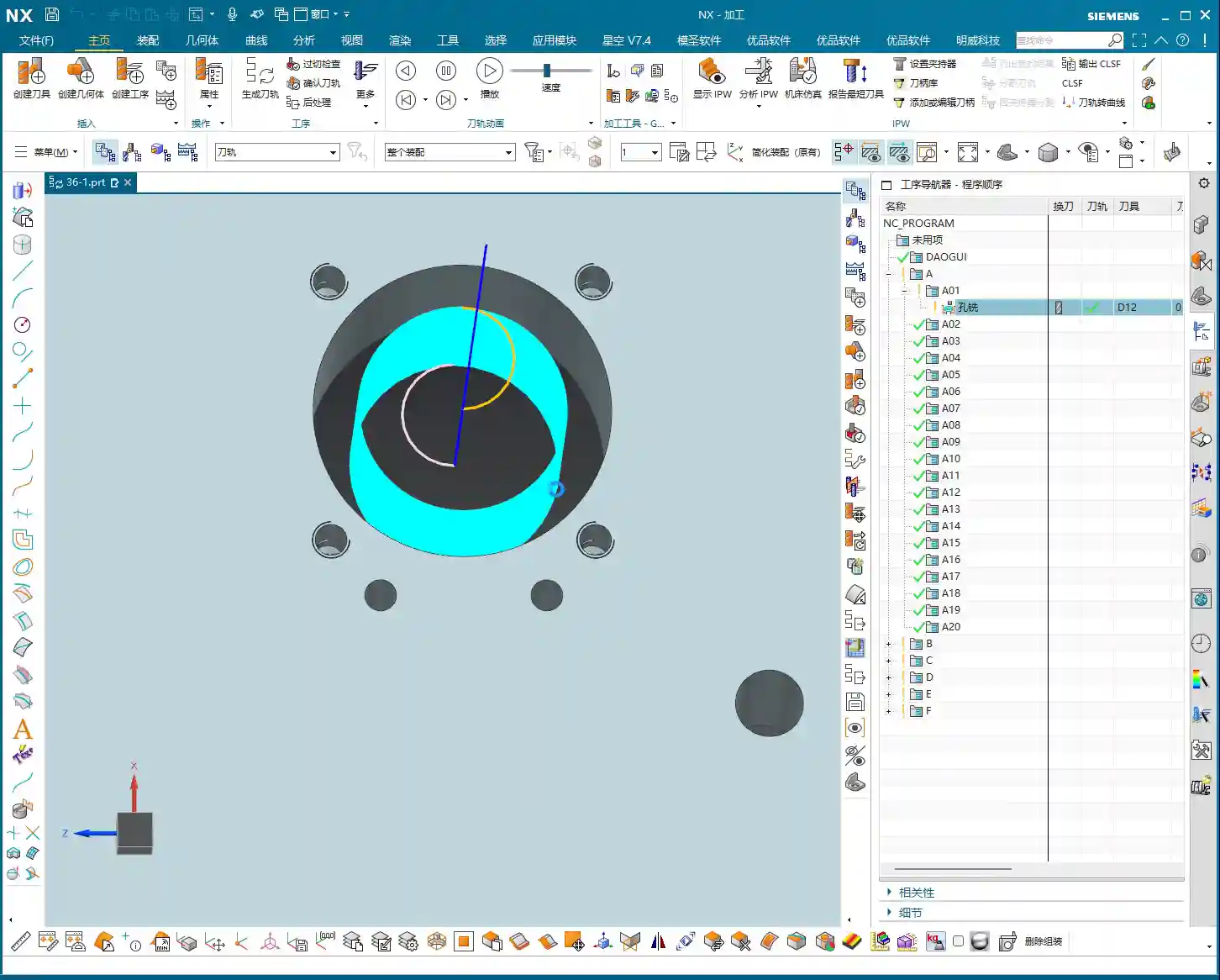
We’ve pretty much covered the specialized hole features combined with the bottom surfaces we discussed previously. Select a hole, machine it, and you’re done. But have you noticed that it defaults to a single pass, spiraling down along the outer contour? If the hole is small, or if you’ve pre-drilled a pilot hole and left some stock, a single milling pass works fine.
However, if you encounter a larger hole that cannot be covered in one pass, the default hole milling mode can be a bit awkward. In such cases, I often tell my apprentices: Don’t stubbornly stick to hole milling; if it’s not working, switch to Planar Milling! Treat the hole as a planar region and use the Roughing mode of Planar Milling; you can still achieve the desired result, and often with higher efficiency. Why? Because what is the Hole Milling command best at? It’s about spiraling from top to bottom in a single pass to clean out the hole. That’s its specialty!
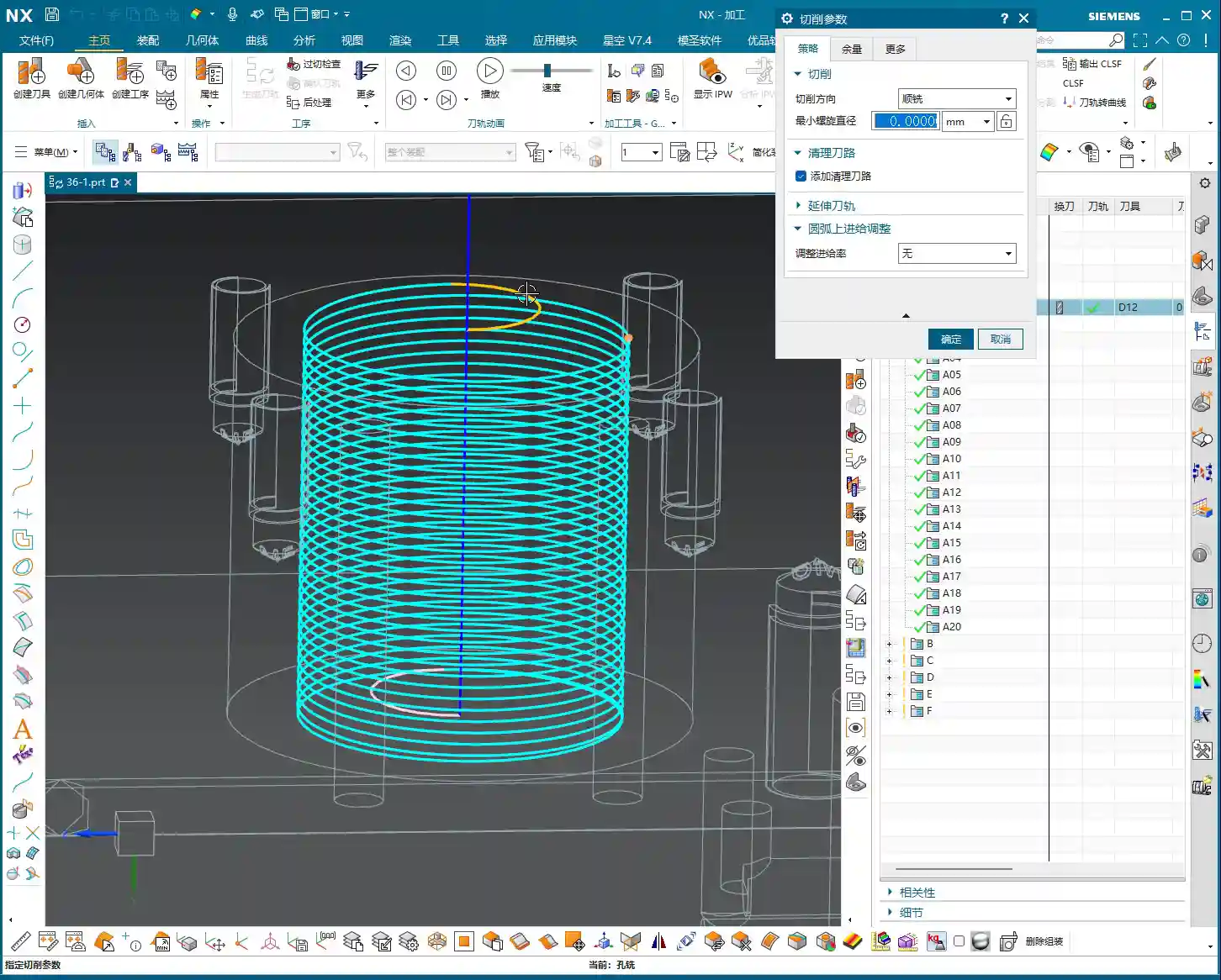
But then again, it’s Siemens NX; it has many functions. Hole milling can actually achieve similar results to planar milling, but it depends on how you adjust the parameters. Let’s start with the most commonly used “Helical” mode.
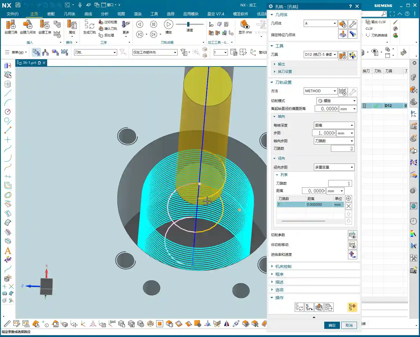
Detailed Explanation of Helical Cutting Mode
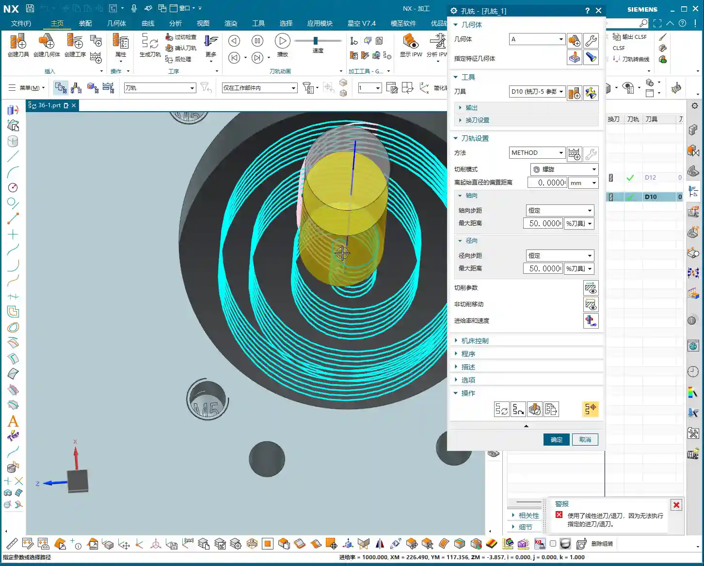
This “Helical” mode is my preferred choice and one I often select in my NX templates. It’s efficient and provides stable cutting. It’s the default, so you can generally use it directly without overthinking. We’ll mainly look at the following parameters:
Axial Distance (Step-down)
This Axial Distance, simply put, is how much Depth of Cut (DOC) you take downwards with each helical turn. For example, if I set it to 0.3 mm, the toolpath will be dense, and the cutting force will be uniform. If you set it to 1 mm, the toolpath becomes sparse, and the Depth of Cut (DOC) suddenly increases. Especially with hard materials, uneven tool loading can easily lead to chipped edges or even direct tool breakage! Therefore, this parameter must be determined based on your tool material, workpiece material, and machine rigidity. Don’t just rely on software simulations; observe the actual cutting sparks and sounds!
Number of Radial Passes (Helical Turns)
Next is the Number of Passes. For this parameter, I advise you not to mess with it normally! Set it to 1. If you set it to 2, 10, etc., it will divide the milling into several layers. After milling one layer, it will retract the tool, then mill the next layer. This results in too many air cutting moves, significantly reducing efficiency, and the impacts from retracting and re-engaging the tool also increase tool wear. What are we aiming for? One continuous pass, clean and decisive!
Radial Distance (Toolpath Offset)
This Radial Distance parameter is quite interesting. The default is 0, meaning it completes one turn. If you set a value, say 10 mm, it will add another pass or several passes on the outer circumference, effectively milling the hole larger. This is precisely to address the issue mentioned earlier, where a tool cannot mill a large hole in a single pass. It will first helical mill the interior, then retract the tool, and then helical mill another circle, offset by 10 mm from the outside. Although this method involves one more tool retraction than a single continuous pass, for large holes that cannot be covered in one go, it’s more flexible than simple planar milling, especially when high verticality of the hole wall is required.
Remember, these parameters are not rigid; they depend on the size of your chosen tool, the hole diameter, and your cutting strategy. If your set radial distance is greater than the stock remaining for the hole, there will be no room for additional passes, and the software will optimize it out.
Key Parameters: Top and Bottom Offset
Next, let’s discuss two very practical parameters that many newcomers overlook but are crucial for protecting tools and ensuring machining quality: Top Offset and Bottom Offset.
Top Offset: The Tool’s “Soft Landing”
I’m telling you, this Top Offset is extremely important! It means that the tool will perform an additional air cut for a certain distance above the actual machining top surface before formally starting to cut. For example, if you set it to 10 mm, the tool will start its helical motion 10 mm above the hole’s top surface and then gradually cut downwards. Why do we do this?
Tool Protection: Especially when milling hard materials, if you let the tool “plunge” directly into the workpiece surface to start cutting, the impact force is very high, and the tool tip can easily chip. With Top Offset, the tool makes a “soft landing,” with cutting forces gradually increasing, significantly extending tool life.
Avoid Surface Scratches: Some workpieces require high surface finish, and direct entry can leave scratches on the surface. An initial air cut allows the tool to enter a stable cutting state.
Managing Stock: If your workpiece has remaining stock on the top surface, such as a cast blank, you can adjust this parameter to have the tool start cutting from above the stock.
Don’t cut corners here, especially during Roughing. Setting a 5-10 mm offset here offers significant benefits.
Bottom Offset: The “Refined Finish”
If there’s a Top Offset, there’s naturally a Bottom Offset. This is also easy to understand: it means the tool will mill a little extra at the bottom of the hole. For example, if you set it to 5 mm, it will mill 5 mm deeper than the defined hole bottom. This parameter is mainly used to:
Thoroughly Clear the Bottom: Ensure that burrs and residual stock at the bottom of the hole are cleaned, especially for blind holes or holes with chamfered or filleted bottoms.
Avoid Tool Marks: Sometimes, when the tool cuts to the bottom, minor tool marks may appear due to changes in cutting force. Milling a little extra ensures a flat and smooth bottom.
Address Positioning Errors: If there are minor positioning errors in your workpiece or Z-axis errors in the machine, extending downwards a bit can compensate for these errors, ensuring the actual machining depth meets specifications.
You can even input a negative value, but that would mean not milling to the design depth, which is generally not recommended. Typically, a 0.5 to 2 mm bottom offset is sufficient.
Stock and Non-Cutting Moves
As for Side Allowance (side stock), that’s straightforward: the amount left for the Finishing pass. We control the top stock through Top Offset. These are standard operations and don’t require much elaboration.
In Non-Cutting Moves, the main focus is on the entry and exit methods. The default Helical Ramp or Arc Lead-in are generally the most suitable, allowing for smooth entry and exit into and out of the cut. This prevents sudden tool impact and reduces Chatter. Unless there are special circumstances, such as an obstruction near the hole, you typically won’t need to consider changing to a Linear Lead-in or similar. If the program is set up correctly, these parameters usually don’t need modification.
Other Hole Milling Modes and Entry Strategies
NX has several other hole milling modes, such as helical out-cut, constant helical, and so on. These modes are actually similar to the Roughing strategies in Planar Milling, all designed to progressively enlarge the hole. In actual work, we use them less frequently, primarily relying on the combination of helical entry with Radial Distance.
Comparison of Various Entry Methods
Take tool entry, for example. “Linear Lead-in” means plunging straight in, which creates a high impact on the tool. Unless it’s a particularly soft material or the tool is a drill-mill, it’s not recommended. In contrast, “Helical Ramp” and “Arc Lead-in” allow the tool to maintain stability during cutting, reducing impact. Therefore, under normal circumstances, I always have my apprentices choose helical or arc entry; it’s a fundamental skill for tool protection.
Helical Out-Cut Mode
There’s also a “Helical Out-cut” mode, which processes the hole spiraling outwards from the center, similar to “inside-out” Roughing in Planar Milling. This mode can also be quite useful in certain situations, especially when the hole diameter is large, and the tool cannot machine the entire hole in one pass. Its advantage is a relatively uniform cutting load, but its drawback is a longer toolpath and potentially more air cutting moves.
Summary: Pitfall Guide
Mode Selection: For small holes or pre-drilled holes, use the “Helical” mode for a single, continuous pass. For large holes or those that cannot be milled in one pass, prioritize “Planar Milling” for Roughing, or use the “Helical” mode in Hole Milling combined with “Radial Distance.”
Axial Distance (DOC): Set strictly according to material hardness, tool diameter, and machine rigidity; err on the side of smaller values to prevent tool chipping.
Number of Passes: Keep at 1, aiming for a single, continuous pass to improve efficiency.
Top Offset:Essential for Roughing, providing the tool with a “soft landing” and extending tool life. The value is usually set to 5-10 mm.
Bottom Offset: Ensures a clean hole bottom and compensates for minor errors. The value is usually set to 0.5-2 mm.
Entry Method: Prioritize “Helical Ramp” or “Arc Lead-in” for smooth tool entry, avoiding impact.
Parameter Flexibility: Memorizing parameters is useless; the core is to understand the machining logic behind each parameter and its impact on actual cutting, then adjust flexibly according to practical conditions.
Alright, that’s all for today. In NX Programming, practical experience is key! Watch more, learn more, and get hands-on experience, and you too can become a master!
👤 About the Author: The author is a veteran CNC machining professional with 15 years of industry experience, specializing in UG NX programming. This article is an original work representing personal practical insights.
⚠️ Copyright Notice: Unauthorized reproduction or distribution without prior communication is strictly prohibited.