📝 Key Takeaways: Master Wang explains Siemens NX Cavity Mill operations and blank definition. He emphasizes the importance of 3D Roughing with Cavity Milling, especially for complex surface parts. Detailed guidance is provided on how to correctly specify the part and create the blank, with a focus on “net-size blanks” applications. Key analysis covers Roughing, Re-Roughing, and Corner Cleanup functions, along with practical tips for avoiding fixtures and effectively using check geometry. He advises beginners that specifying the blank usually eliminates the need for additional cut area definition, preventing unnecessary complexity. Understanding the blank logic is crucial for improving machining efficiency and preventing tool collisions.
Hello everyone, I’m Master Wang. We’ve pretty much covered all the 2D operations by now. I’ll find an opportunity to go over some of the less commonly used commands later. Starting today, we’re getting serious and diving straight into 3D. 3D machining is a completely different beast from 2D; it’s several times more complex and requires much more attention to detail. Listen up: the first critical command in 3D machining that we’ll discuss today is Cavity Mill.
Master’s Insights: Why Learn Cavity Milling?
You need to know that Cavity Mill is a powerful roughing tool in 3D machining, especially when dealing with oddly shaped, complex surface parts. It’s perfectly suited for the initial machining of mold cavities, castings, and forgings. Why? Because it can efficiently and quickly remove excess material, laying a solid foundation for subsequent finishing passes.
Think back to the 2D milling operations we discussed, like Floor Wall Mill and Planar Mill. What can they do? They handle simple tasks involving planar surfaces and straight walls just fine. But if your part has an angled surface, a radius, or even an irregular freeform surface, those two operations are useless; they can’t handle the roughing. So, when you encounter 3D irregular parts, Cavity Mill is your go-to choice.
(Master Wang demonstrates by opening a complex part model in the NX interface while speaking.)
Coordinate System and Part Confirmation: Laying a Solid Foundation
First step in any job: lay a solid foundation. You need to set up the Work Coordinate System (WCS) correctly. I usually pick a few points to quickly check if it’s centered on the part and if the Z-axis direction is correct. Even if the Z-axis isn’t perfectly upward, it’s fine as long as the general direction is correct and the program can be generated. Don’t just focus on how perfectly drawn it is in CAD; real machines aren’t always that accommodating.
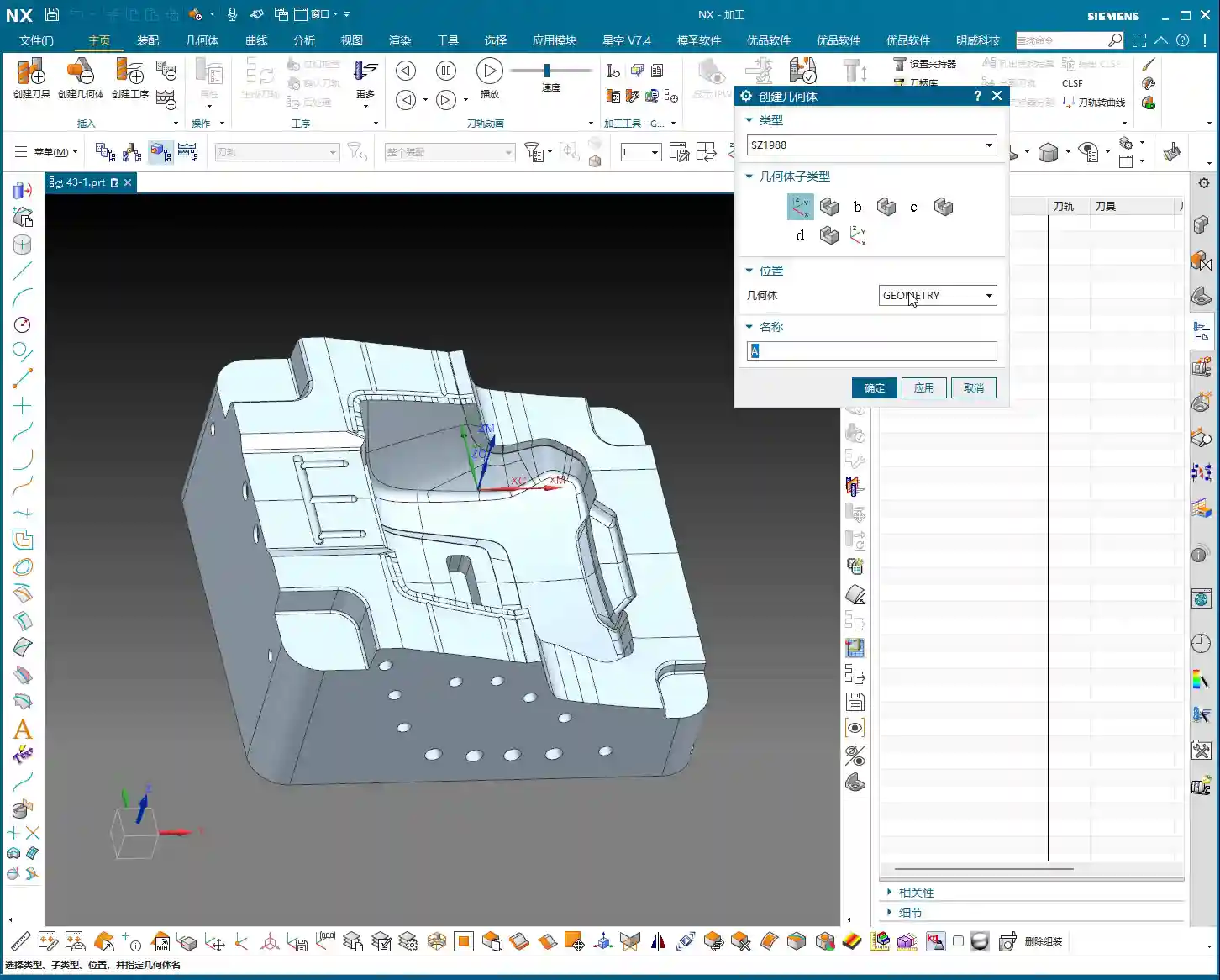

Next, we need to tell NX which part you’re machining, which means Specifying the Part. It’s simple: just select your workpiece.(Master Wang demonstrates quickly checking the coordinate system using a “point-to-point” method and selecting the model as the part.)
You rookies, when you’re analyzing a part, don’t just look at whether the model looks nice or not. I habitually use the measurement tools to roughly gauge the part’s length, width, and height, so I have a mental reference. You need to have a good sense of the job’s size to decide what tool size to use. For example, if this part is around 100-plus millimeters in length, width, and height, it’s not particularly large, so you have a good starting point.
Cavity Mill Core Functions: Roughing, Re-Roughing, Corner Cleanup
This Cavity Mill command primarily handles three tasks: Roughing, Re-roughing, and Corner Cleanup.
Roughing: The First Step to Remove the Bulk!
This is the most basic step, what we call “roughing”. You use a large tool to quickly remove the majority of the material, milling out the part’s general shape. Don’t underestimate this step; if roughing isn’t done well, subsequent finishing passes will be a nightmare, and tool wear will be excessive.

Re-roughing: Don’t Underestimate Its Importance!
“Re-roughing” sounds like it only happens twice, but that’s not the case. It refers to using smaller tools than the first roughing tool to clean up areas that the larger tool couldn’t reach or couldn’t effectively cut. For example, after roughing with a Φ20 tool, if some small corners or radii still have uncleared material, you’ll need to switch to a Φ10 tool for re-roughing. If the Φ10 isn’t enough, then switch to a Φ6. This “re-” can be three, four, five, or even more passes. The key is to gradually reduce the tool diameter to clear the remaining material and leave a uniform stock for finishing. If this step is done well, finishing passes will be much easier.
Corner Cleanup: Attention to Detail is Key
This is even more detailed. As the name suggests, it’s specifically for cleaning up internal corners of the part. It ensures all internal corners meet the design requirements for surface finish and dimensional accuracy. Especially in mold machining, if internal corners aren’t properly cleaned, it can be a critical failure.
The Utmost Importance: Correct Blank Specification and Underlying Logic
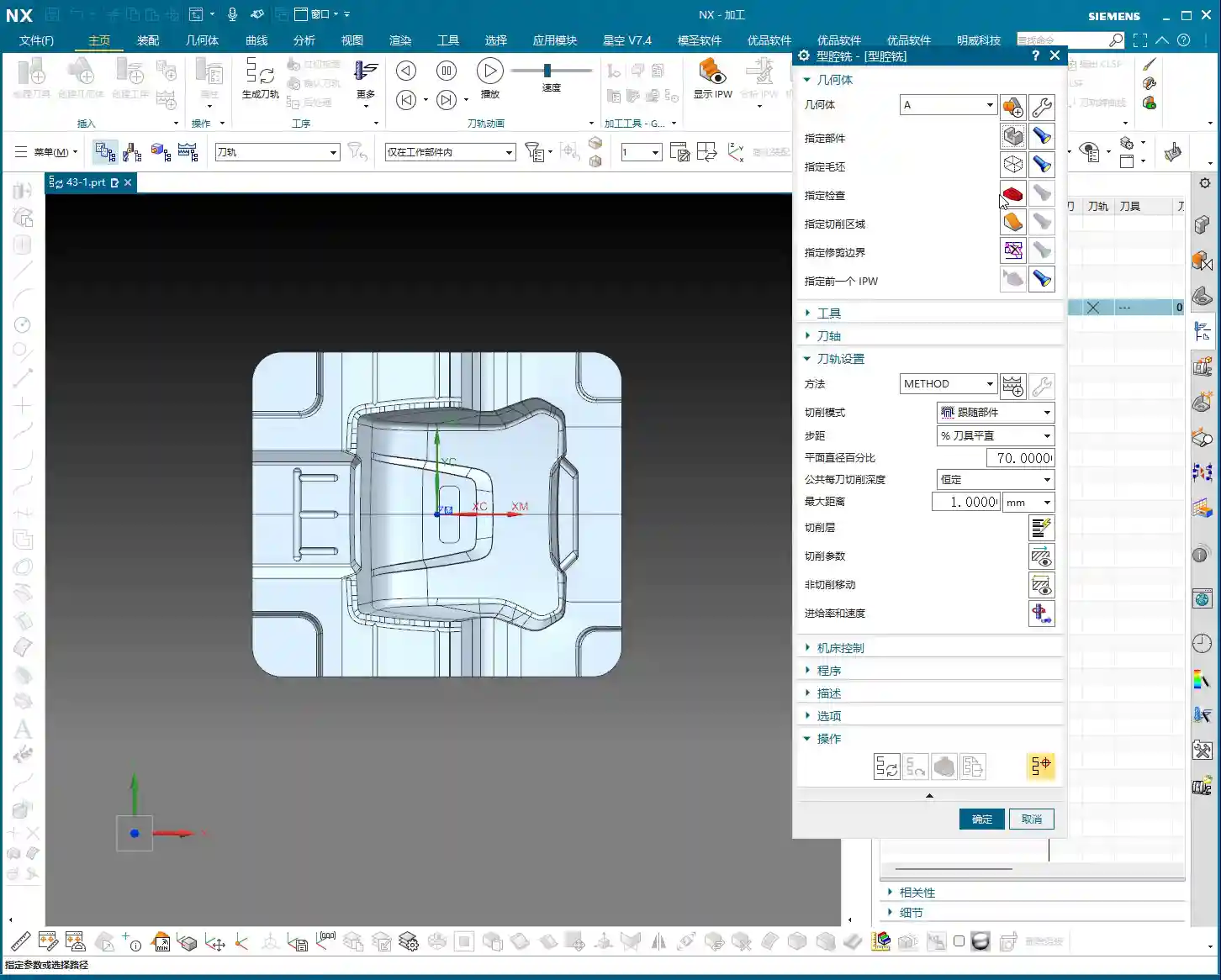
Listen closely, here’s one of the most important aspects of Cavity Milling: you “must define the part and blank geometry.” Without a blank, where do you expect the software to start roughing? It has no idea how large the raw material you’re working with is. Therefore, blank definition is paramount!

Specify Part: Your Target!
As we discussed earlier, this is the final part model you intend to machine. It tells NX what your ultimate goal looks like.
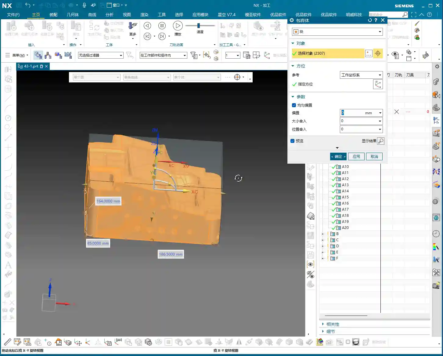
Specify Blank: Raw Material – Get It Right!
The blank is the raw material you’re starting with. You need to tell NX what this raw material looks like and how large it is, so it knows where to begin cutting and how much to remove. In NX, blanks are typically created using a “Bounding Body,” such as a block or cylinder. I’ll directly select “Bounding Body,” choose “Block” as the type, and set the offset to 0.
Why an offset of 0? Because the material I have on hand is a net-size blank. This means the material might already be a precision casting, a precision forging, or has undergone prior roughing operations, so its external dimensions are very close to the final part’s shape, or rather, it is the part’s actual size. Of course, if your raw material is oversized compared to the part, you’ll need to set the offset accordingly, for example, leaving a 1mm allowance all around. But for today’s example, we’ll treat it as a net-size blank.
(Master Wang creates a bounding body blank in NX and selects it.)

So, however large the material you actually have, that’s how large you should create and select your blank. This reflects the most realistic machining scenario; don’t just imagine it.
Specify Check Geometry: Stay Clear of Collision Zones!
Collision risk is high here! Think about it: when you machine a part, don’t you often use fixtures and clamps to hold the workpiece? You definitely don’t want the cutting tool to hit them, right? At this point, you need to model these fixtures and clamps, then specify them as Check Geometry. This way, when NX calculates the toolpath, it will automatically avoid these areas, ensuring your tool doesn’t collide with the fixtures. It saves you headaches and effort.
You could also include the fixture models within “Specify Part” to make the tool avoid them, but using Check Geometry is clearer and more logical. Whichever method you use, the goal is clear: no tool collisions – that’s the absolute bottom line!
Specify Cut Area: Unnecessary Complication or Valuable Addition?
What does “Specify Cut Area” mean? It tells the software precisely where you want the tool to cut. But my apprentices, you must remember this: if you’ve already defined the blank, absolutely do not easily go and specify the cut area!
Why? Because once you’ve specified the part and the blank, NX already clearly understands where there’s material to remove and what the finished part looks like. It figures out the cut area itself. If you manually specify it again, especially by selecting the entire part, how is that different from not specifying a blank at all? It can easily mess up your toolpaths and even cause issues.
Typically, selecting either Specify Blank or Specify Cut Area is sufficient. Personally, when I’m working, in 90% of roughing scenarios, I only specify the blank. This is because the blank represents the actual incoming material, and it most accurately defines where excess material exists. Only in very specific situations, such as when you only need to machine a small region of the part, should you consider specifying a cut area. But that’s a topic for another time. For now, don’t overthink it, just remember my experience.
Summary: Pitfall Avoidance Guide
- Don’t just rely on software simulations; watch the cutting sparks! No matter how brilliant your programming is, the final result depends on the machine. Spend more time on the shop floor, observing actual cutting, listening to the sounds, and watching the sparks – that’s where true skill lies.
- Blank definition is the cornerstone of Cavity Milling; understanding it will yield twice the results with half the effort. The blank is the raw material you start with; it dictates where the tool begins “eating away” material. Define it accurately, and your toolpaths will naturally be logical and efficient.
- After specifying the blank, avoid unnecessarily specifying the cut area unless there’s a special circumstance; it only adds complexity. The software is smart; once you provide the blank, it knows where to cut and where not to cut. Don’t overcomplicate things.
- Always avoid fixtures, either by using check geometry or by planning your process in advance. This is basic safety common sense. One tool collision can waste days of work, or even damage equipment and tooling.
👤 About the Author:
The author is a veteran CNC machining professional with 15 years of industry experience, specializing in UG NX programming. This article is an original work representing personal practical insights.
⚠️ Copyright Notice: Unauthorized reproduction or distribution without prior communication is strictly prohibited.