📝 Key Takeaways:
Practical Machining of Complex Parts in Siemens NX
Hello everyone, I’m Master Wang. Today, we’re going to discuss machining this particul…
Hello everyone, I’m Master Wang. Today, we’re going to discuss machining this particular part in Siemens NX. Don’t let this model’s apparent simplicity fool you; there’s a lot more to it than meets the eye. Having mentored apprentices for many years, I’ve noticed that many people just know how to click buttons, but get lost when faced with real-world problems. Today, I’m going to personally teach you these practical tips and tricks—the “things you won’t learn from textbooks.”
I. Part Analysis and Preparation: Sharpening the Axe Before Chopping Wood
Listen up. When you get a new part, don’t rush into cutting. You need to “see through” the part first—that’s what we call “sharpening the axe before chopping wood.”
1. Geometric Feature Inspection: Radii and Draft Angles
First, use Siemens NX’s built-in analysis tools, such as “Draft Analysis” and “Geometric Properties.” Check the draft angles. If everything is green, it means there are no negative draft angles, and the tool can descend smoothly. If you see red, be cautious; you’ll need to find a way to avoid it or redesign the process.

Next, inspect the radii (R-angles). For this part, I see R5, R8, and R3. You must remember these areas, as they directly determine the maximum tool size you can use and your Corner Cleanup strategy. This is like reconnoitering the terrain; understanding the complex areas beforehand saves you a lot of detours.
Practical Tip: Around 01:30, we discover a critical location where the CAD model surprisingly lacks a radius! This is absolutely unacceptable in actual machining. Without a radius, the tool can easily “gouge” the material and won’t machine the area correctly, often leading to stress concentration or even a scrapped part. In such cases, we can’t just wait for the design department to revise the drawing. We must proactively add a radius, for example, R5.5. This demonstrates your ability to solve problems on the shop floor; don’t just follow the drawing, consider if the tool can actually cut smoothly.

2. Stock Definition and Coordinate System Setup
For Stock definition, my personal habit is to set it to 100%. This ensures the tool has enough safe distance before engaging the workpiece, reducing the risk of accidents. You can also adjust it based on the actual raw material dimensions, but remember, safety first.
Setting up the Work Coordinate System (WCS) is an old topic; it must be correctly oriented and aligned with the machine’s zero point. This is the absolute fundamental; if this step is wrong, everything else is moot.
II. Roughing Strategy: Tool Selection and Path Optimization
Roughing aims to quickly remove most of the material, leaving adequate stock for finishing. But fast doesn’t mean careless; tool selection and toolpath planning are crucial.

1. Area Roughing: Cavity Milling and Toolpath Pitfalls
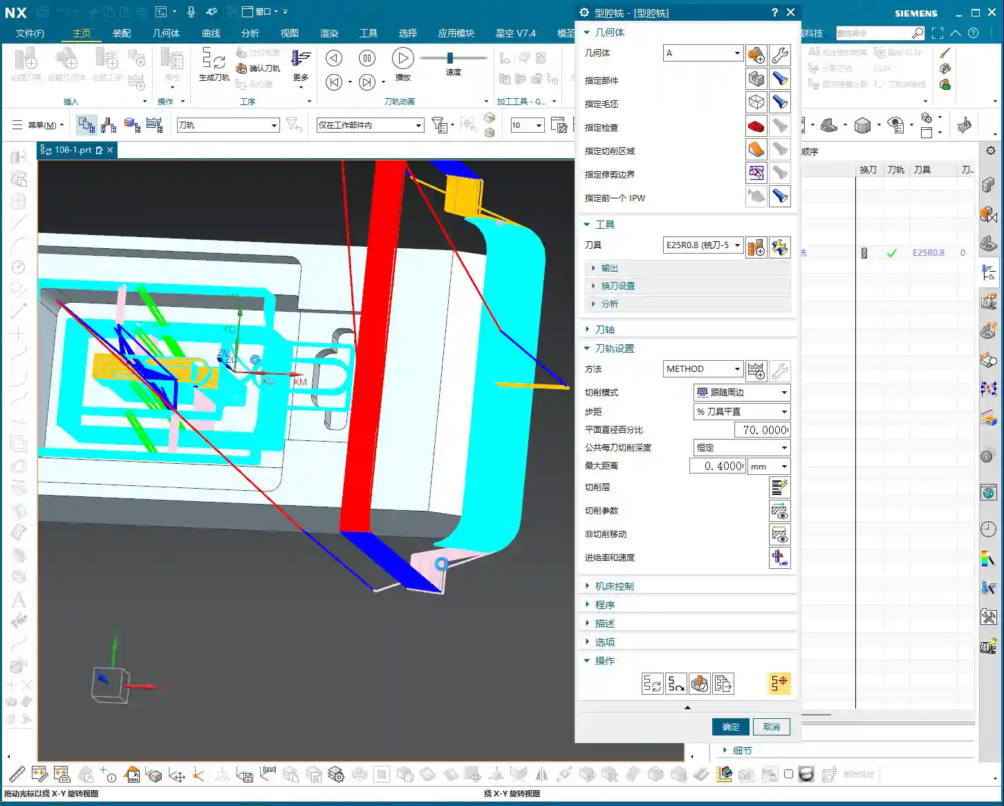
For roughing the top and most other areas, we can use a “Cavity Milling” operation. Initially, we can use a Φ6 flat-end mill, followed by a Φ10 ball-end mill for Corner Cleanup; these are standard practices. However, this part has many areas of different widths, such as 60mm, 50mm, and 25mm sections. This means you’ll need to progressively switch to smaller tools—that’s common sense.
But here’s a pitfall: the video initially uses “Delete Blanking” (DBT) for roughing, which requires you to repeatedly select regions, making it very cumbersome, and the toolpath might not be ideal. In such cases, it’s more advisable to use “Cavity Milling” with well-defined boundaries. Don’t just rely on the software’s simulation; observe the sparks during actual cutting! The color and shape of the sparks will tell you about the tool’s load condition.
For the initial Roughing pass, we selected a Φ25R0.8 bull-nose end mill (or large corner radius end mill). The single Depth of Cut (DOC) was set to 0.2-0.4mm. Don’t think this amount is small; steady progress is key. When you’re first programming, parameters can be slightly conservative; safety first, don’t scrap a part for the sake of speed.
2. Auxiliary Geometry and Path Control
Around 04:22, you’ll notice a “cornering” issue in the generated toolpath: the tool went where it shouldn’t, even running outwards for a segment. This kind of toolpath is extremely dangerous; at best, it will lead to tool collision; at worst, a machine crash or irreparable part damage. This is what I often refer to as “practical experience you won’t learn from textbooks.”
When you encounter this, the internal cavity might be fine, but the toolpath for the outer wall isn’t perfect. The solutions are:
- Create Auxiliary Geometry: In Siemens NX, create a simple auxiliary body and place it in the area where you want to restrict the tool. Then use it as a boundary for the machining region, forcing the tool to follow your intent.
- Delete and Regenerate: If the toolpath is too messy, it’s better to delete the program directly and regenerate it with a different strategy or tool. Don’t expect to “patch it up” and solve the root problem.
Around 05:30, I directly deleted the problematic program. Because some toolpaths will only cause problems if forced, it’s better to be decisive and start from scratch; that’s the mark of an experienced professional.
III. Finishing and Corner Cleanup: Balancing Precision and Efficiency

Once roughing is complete, we move on to finishing and Corner Cleanup, focusing on part dimensional accuracy and surface quality.
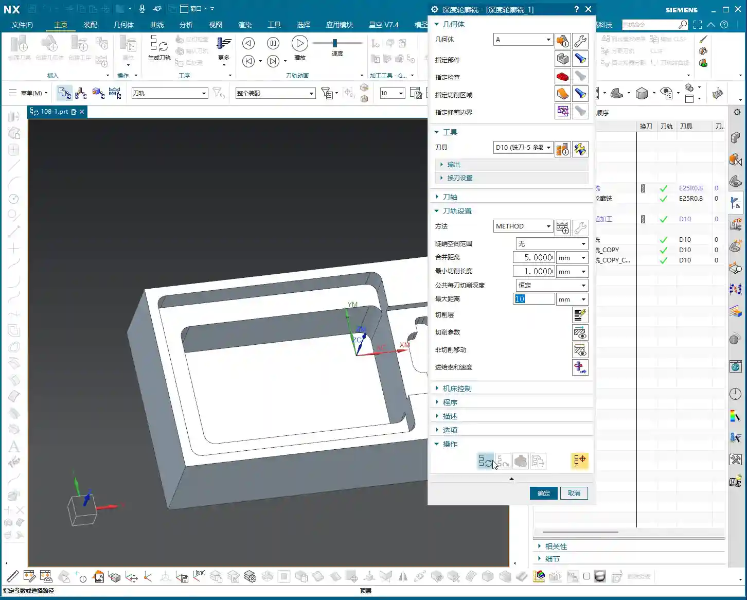
1. Deep Milling: Finishing Inner Cavity Walls
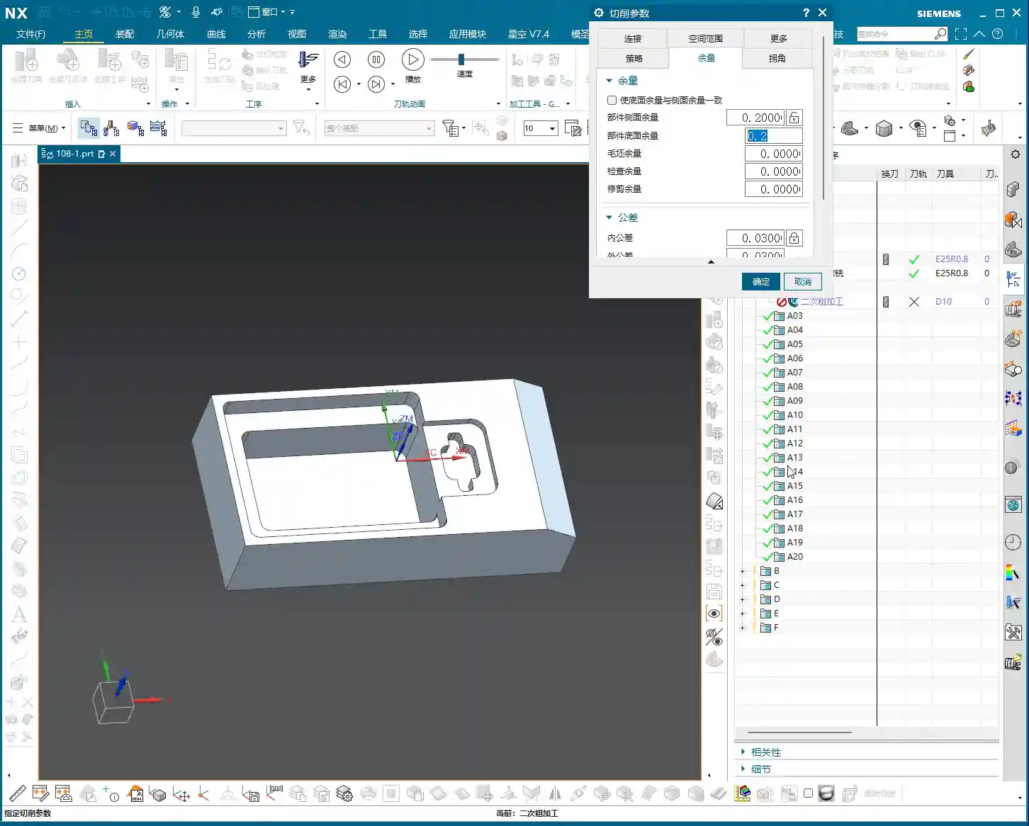
For machining the inner cavity of the part, we can use “Deep Milling.” Again, use a Φ25R0.8 tool. When selecting machining faces, clearly distinguish between sidewalls and the bottom surface. We can temporarily avoid machining the bottom surface by setting a +1mm stock allowance, focusing on the sidewalls first.
The Finishing allowance must be precisely set, typically 0.2mm or 0.15mm. Select a linear cutting method, and the Stepover (lateral feed per pass) can initially be set to 55%. For the final finish pass, change it directly to 0 to run a single pass all the way down, which ensures surface finish quality.
2. Corner Cleanup Strategy and Reference Tool
Corner Cleanup is a critical step in finishing, especially for internal corners that roughing tools couldn’t reach. This time, we’re using a Φ10 ball-end mill for Corner Cleanup, with a Depth of Cut (DOC) of 0.3mm and a stock allowance of 0.15mm. Here’s a very important trick: when setting up a Corner Cleanup operation, you absolutely must select the roughing tool you used previously (in this case, the Φ25 tool) as the “reference tool.” This tells Siemens NX where remaining stock needs to be cleaned up, allowing it to precisely generate Corner Cleanup toolpaths and avoid idle passes.

However, at 09:12, the Corner Cleanup toolpath “misbehaves” again, running into areas it shouldn’t. Don’t panic; this is common. The solution is: precisely select the specific areas or points you want to machine to forcefully restrict the toolpath range. This is much more efficient than blindly changing parameters and is key to improving efficiency and avoiding idle passes. Finally, use a Φ6 tool for fine finishing of particularly small areas, then use a Φ10 tool to finish the sidewalls and bottom surface. This combination ensures the part’s accuracy and surface finish.

IV. Mirroring Operations: The Secret to Efficiency for Symmetrical Parts
For this part, the video only demonstrates one side. But if it’s a symmetrical component, for example, with similar features on both the left and right sides, do we really need to program both sides from scratch? That would be incredibly inefficient! What about efficiency? What about cost?
1. Why Use Mirroring Operations?
This is where our efficiency-boosting tool—Mirroring Operations—comes in. For most symmetrical parts, you only need to program one side, and then use the mirroring function to quickly generate the toolpaths for the other side. The benefits are obvious:

- Significantly reduced programming time: Program one, get two, doubling efficiency.
- Ensured toolpath consistency: Mirrored toolpaths have identical parameters, avoiding potential deviations from manual programming.
- Reduced human error: Automated generation minimizes the chance of mistakes.
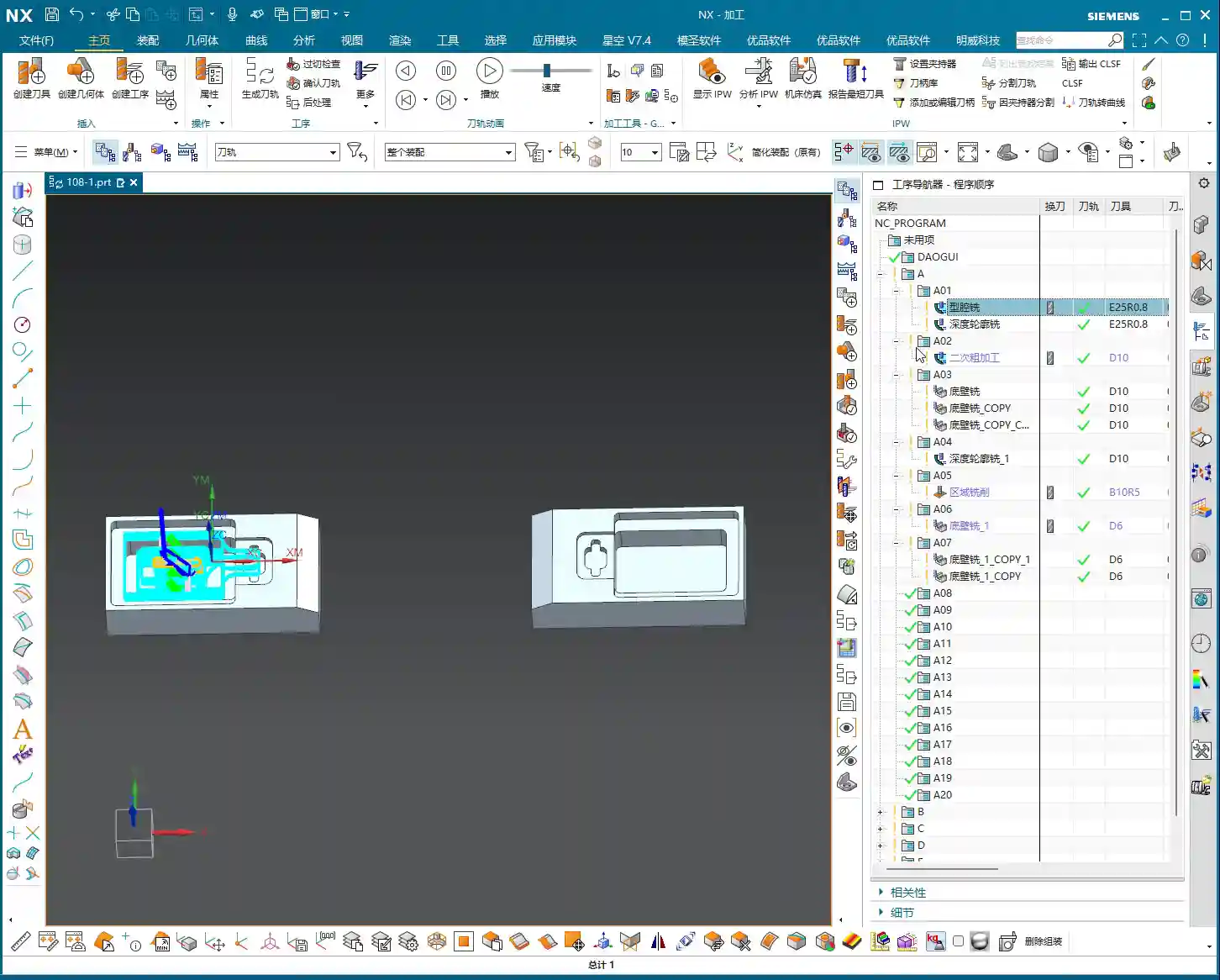
2. How to Implement Mirroring in Siemens NX
Implementing mirroring in Siemens NX is very convenient. In the “Operation Navigator,” you can select the operation or operation group you want to mirror, then right-click. You’ll usually find “Transform” -> “Mirror Geometry” or a direct “Mirror Feature” option. The key is to select the correct mirror plane. This plane is typically the part’s plane of symmetry.
After mirroring, the system will automatically generate new operations for you. Don’t forget to regenerate the toolpaths and verify them. If your machine supports it, the post-processed G-code might contain mirroring commands such as G51.1 or G68, which require both your machine and post-processor file to support them for proper execution.
3. Considerations for Mirroring Operations
While mirroring operations are powerful, they’re not a panacea, and there are pitfalls to watch out for:

- Tool type: If you’re using non-symmetrical, special-form tools, or if the tool’s mounting direction has specific requirements, you need to carefully check after mirroring. Sometimes, you might need to adjust the tool orientation or reselect the tool.
- Fixturing method: For mirrored operations, the part’s fixturing method might also need to be mirrored or redesigned to ensure stability and avoid interference.
- Machine accuracy: Even on the same machine, there might be subtle differences in machining accuracy between mirrored sides, especially with high-precision requirements like ±0.005mm (approx. ±0.0002 inch). In such cases, ensure sufficient finishing allowance and, if necessary, perform compensation machining.
- Post-processing verification: The G-code generated from mirroring operations must undergo thorough simulation and verification to confirm that the machine can correctly recognize and execute the mirroring commands.
Summary: Pitfalls to Avoid
- Missing radii are common: CAD models are not always perfect; always check critical radii before machining. Add them if necessary, or compensate through process planning. Don’t expect design to solve all issues.
- Sharp corners in toolpaths are a hidden danger: Relying solely on software simulations isn’t enough; you must use your cutting experience to judge the tool’s load condition. When toolpaths run wild or have “sharp corners,” auxiliary bodies and point-selected regions are powerful tools for controlling the toolpath.
- Stock allowance settings must be precise: Roughing and finishing allowances need to be allocated appropriately. During Corner Cleanup operations, always remember to select the “reference tool” to allow the system to calculate the remaining stock and avoid idle passes.
- Mirroring operations are powerful tools when used correctly: For symmetrical parts, mirroring can significantly boost efficiency. However, you must consider the impact of tooling, fixturing, and machine accuracy; it’s not a simple one-click solution.
- Understand the implications of parameter modifications: Don’t just “randomly change” parameters. Every parameter has a physical meaning and an impact on the machining results. You need to know what you’re changing, why you’re changing it, and what the consequences will be.
👤 About the Author:
The author is a veteran CNC machining professional with 15 years of industry experience, specializing in UG NX programming. This article is an original work representing personal practical insights.
⚠️ Copyright Notice: Unauthorized reproduction or distribution without prior communication is strictly prohibited.