📝 Key Takeaways:
Pre-Programming Analysis for Multi-Process Parts
Alright folks, I’m Old Wang, your Master Wang. Today, we’re skipping the theoretical fluf…
[VIDEO_HERE]
Alright folks, I’m Old Wang, your Master Wang. Today, we’re skipping the theoretical fluff and getting straight to the practical stuff. I’m going to walk you through how to analyze a multi-process part – this is the crucial first step before programming. A solid analysis upfront will save you a ton of trouble down the line!
Initial Part Analysis: Know Your Part, Win the Battle
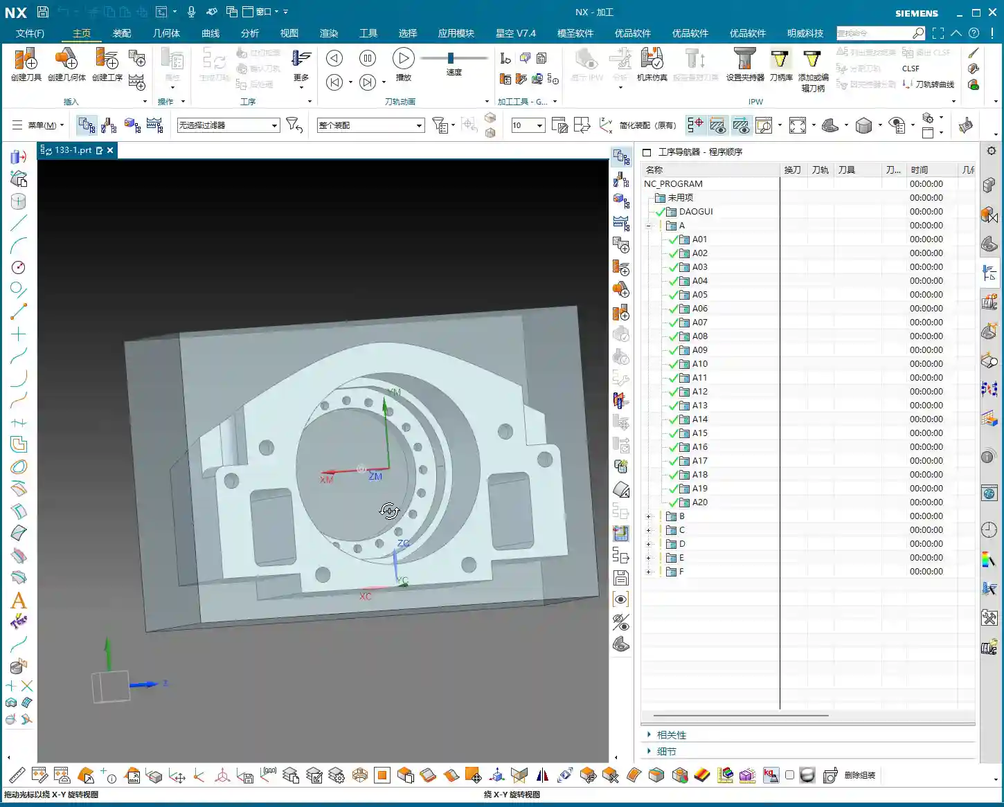
Part Overview and Machining Surface Identification
Now, take a look at this part. It’s a 3-axis component, seems straightforward, but there are plenty of intricacies in machining it. It has four main machining surfaces: a front face, a back face, and two side faces. Don’t underestimate it just because it’s a 3-axis part; if you don’t plan your machining sequence and fixturing strategy carefully, you’ll definitely run into trouble.
Listen up, while theoretically you could machine it flat, in practical operations, especially for certain deep pockets or side features, I prefer to machine it vertically. This allows for better control over tool stick-out, reduces chatter, and improves machining efficiency and surface quality. Don’t underestimate this decision; it directly impacts your subsequent fixture design and toolpath strategy.

Material Properties and Raw Stock Considerations
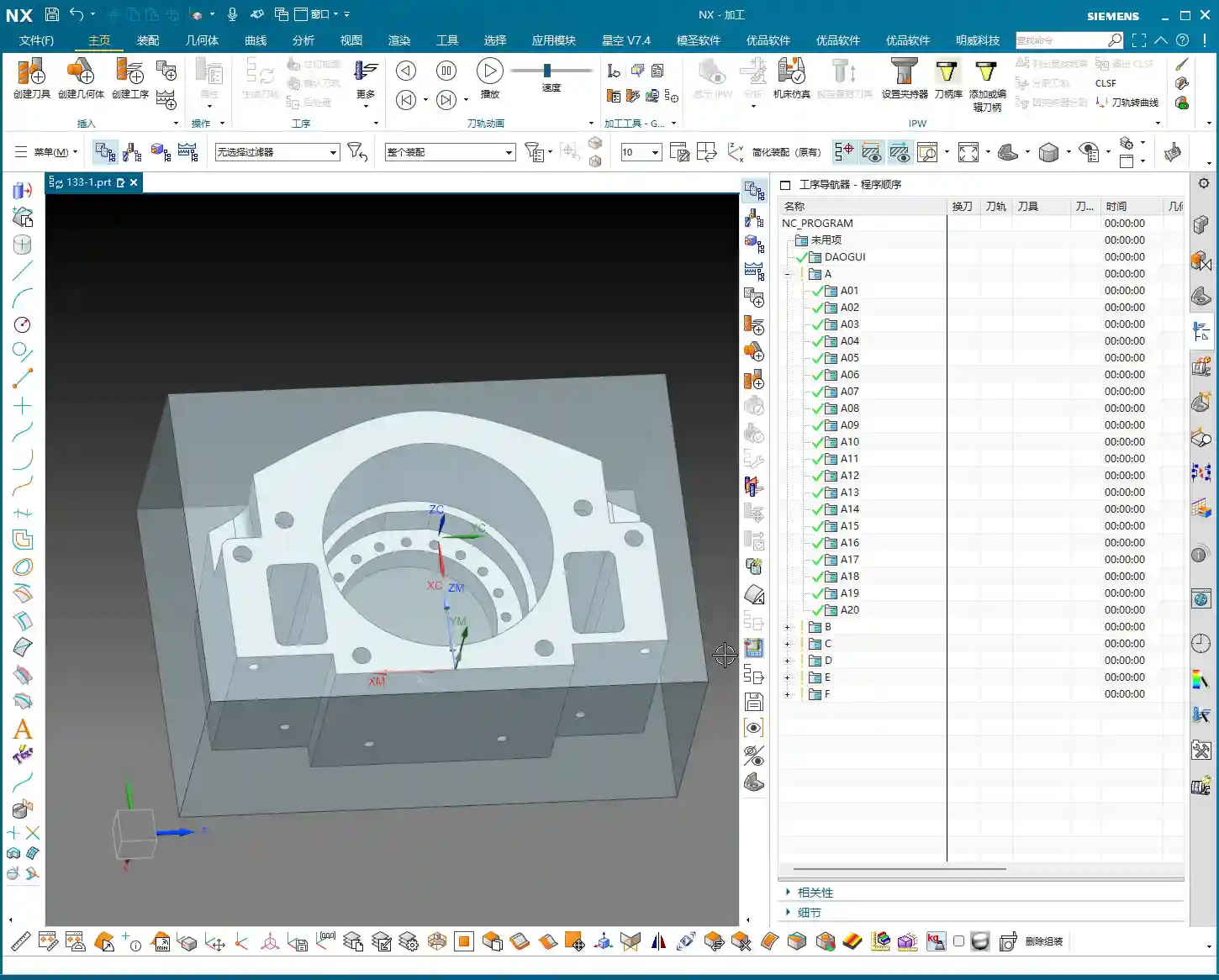
The material for this part is 3Cr13, which is fairly hard. You need to pay close attention to tool selection and cutting parameters during machining. Don’t just chase speed and burn up your tools; that’ll drive up costs. Also, this is customer-supplied raw stock, and it’s quite large. This reminds us that the dimensions and shape of the raw stock are the starting point for programming. We must determine your machining origin and the stock allowance distribution for each operation based on the actual raw stock condition.
For this job, we’ll work directly with these actual raw stock dimensions. We won’t perform any additional Face Milling; we’ll jump straight into Roughing. This isn’t laziness; it’s a decision based on the actual raw stock, reducing unnecessary operations saves time and cost.
Preliminary Process Flow Planning
Let me outline the overall machining strategy for you first; this is our “machinist’s mindset”:
- Roughing the First Face: First, rough the “back face” of the part. This face needs to provide sufficient datum features and stock allowance for subsequent flip-over machining. We’ll leave a 3 mm roughing stock allowance. For internal pockets designed for weight reduction, we can leave slightly less, for example, 1 mm, but the outer contour and critical dimensions will still have a 3 mm allowance.
- Roughing the Second Face after Flipping: Flip the part over and rough the “front face,” leaving a 3 mm allowance as well.
- Heat Treatment: After roughing, the part needs to undergo heat treatment to relieve internal stress and increase hardness.
- Finishing after Heat Treatment:
- First, finish certain datum faces using manual grinding or specific tools.
- Then, clamp it in a vise and finish the front face.
- Next, use a face mill to finish machine the back face.
- Flip it again, and use a face mill to finish machine the other face.
- Finally, orient the part vertically and finish machine the side features.
In total, that’s six operations: two roughing passes and four finishing passes. This sequence is battle-tested and ensures maximum precision and efficiency.

NX Slope Analysis: Identifying Potential Toolpath Issues
In NX, don’t rush into generating toolpaths. First, run a Slope Analysis. This will quickly help you identify if the part has undercuts or insufficient clearance areas. For example, if you view it from above and everything is green, there are generally no undercuts. But if a certain face appears as an undercut from a particular angle, and we’re planning to machine from that direction, then we’ll need to adjust the process. After analyzing this part, we found no significant undercuts, which keeps things straightforward and saves a lot of headaches for subsequent programming.
Remember this: While we can set aside design drawing tolerances for programming practice, in actual machining, when precision requirements reach levels like ±0.005mm, you absolutely must consider tool compensation. During the programming phase, stick to theoretical dimensions and leave sufficient stock allowance. Then, fine-tune during finishing by using the machine’s tool compensation function. That’s a veteran machinist’s secret.
NX Programming in Practice: Strategy First, Toolpath Optimization

Establishing Coordinate Systems and Machining Datums
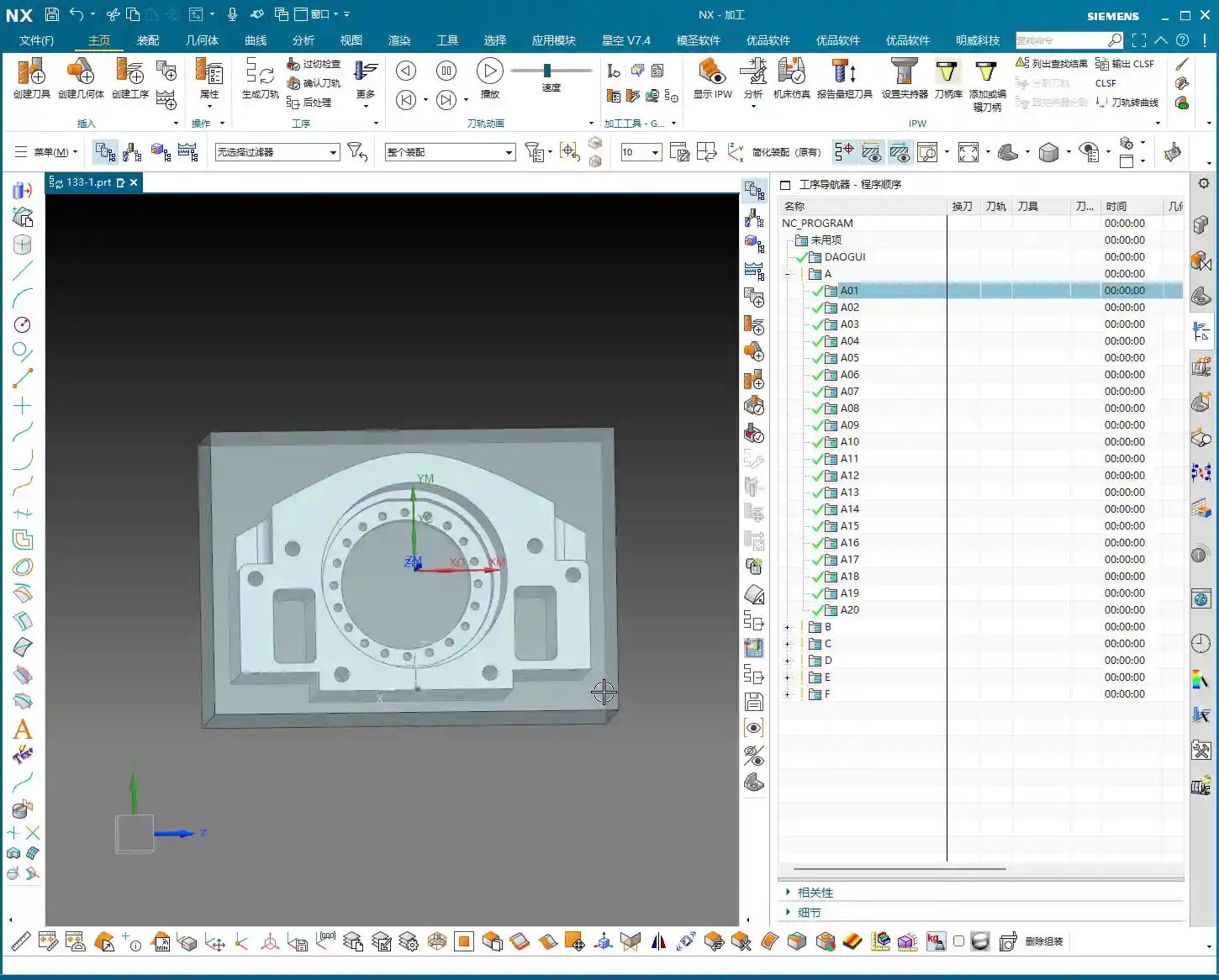
The first and most crucial step in programming: establishing your coordinate system and machining datums.
In NX, first click to create a coordinate system. Use the automatic detection feature to place the coordinate system at the center of the part’s top face, with the Z-axis pointing upwards. This top face will serve as our zero datum (Z=0) for all subsequent machining operations.
Here’s a tip: Before actual machining, this top face must first be face milled (Face Milling) with an end mill to make it flat and smooth, ensuring an accurate datum. Don’t underestimate this step; if your datum isn’t accurate, all subsequent machining will be wasted. After face milling, we’ll then set the Z-axis zero point on this newly milled flat surface. For our raw stock, we’ll simply define it as a rectangular block, roughly 200 by 100-something millimeters, and quite tall.
Roughing Tool Selection and Path Planning
Next up is roughing tool selection, which must be based on the part’s feature dimensions.
- Internal Pocket Roughing: We measured the internal pocket, and its diameter is approximately 20 mm. Considering corner stock allowance and strength, we can choose a 32 mm diameter, R2.8 ball end mill (or a bull nose end mill with a corner radius) for roughing this pocket.
- External Feature Roughing: Some external features on the part have widths in the 30+ mm range. Initially, we might think of a 16 mm tool, but after a closer measurement, there’s an edge dimension around 30 mm. A 32 mm tool might risk cutting into corners or not fitting. Therefore, for roughing the outer contour, we can use a 63 mm diameter end mill to machine the entire profile, quickly removing most of the stock.
- Roughing for Narrow Slots or Small Areas: For roughing some narrower widths (e.g., close to 16 mm) or detailed areas, we’ll keep a 16 mm diameter end mill on standby. Combining large and small tools like this ensures maximum efficiency.
In summary, for this roughing operation, we’ll stick with these three tools: Ø32mm R2.8, Ø16mm, and Ø63mm.
Regarding toolpath planning, for roughing, we typically choose Cavity Mill. When setting up the path, for efficient chip evacuation and to reduce re-cutting, I’ll select “Follow Periphery” and set it to cut “Outward”. This way, the tool moves from the center outwards, resulting in more stable cutting.

Critical Detail: Through Machining and Subsequent Datums
Here’s a critically important point, listen up! For holes or pockets that need to be machined completely through from one side to provide an accurate locating datum after flipping, we absolutely must perform through machining.
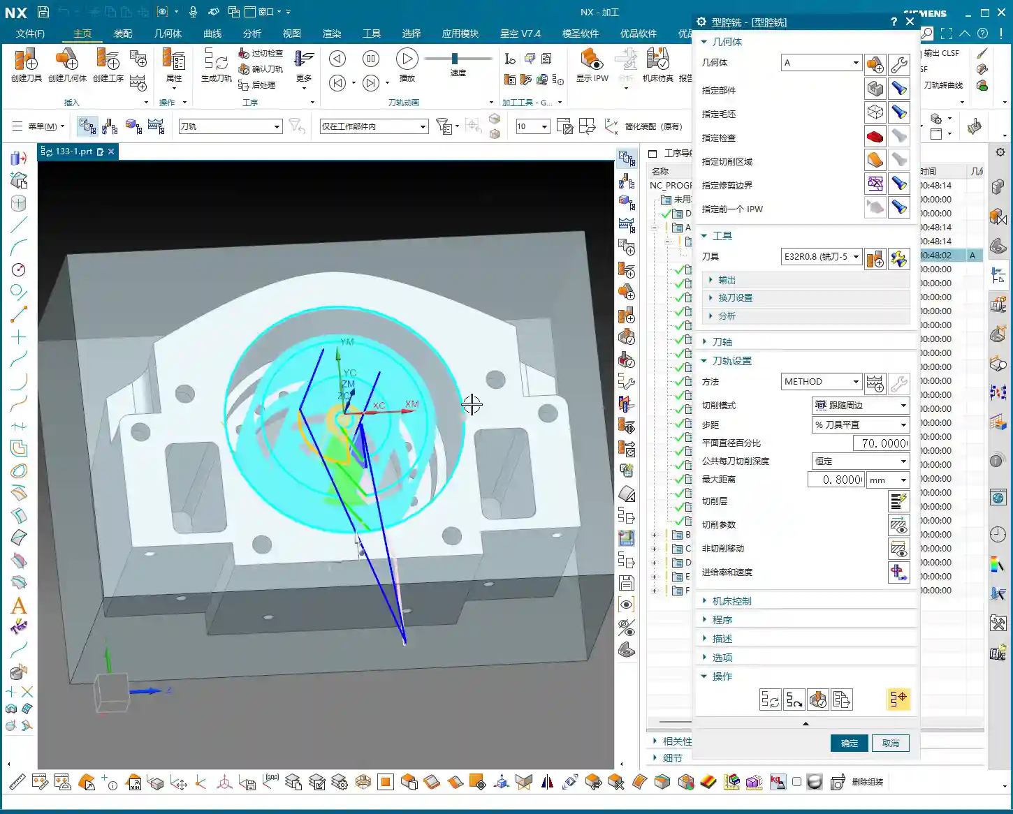
For example, this internal pocket is set to be machined starting from the top face (Z=0). The Depth of Cut needs to extend 4 mm deeper than the theoretical depth. Why the extra 4 mm? Because when we flip the part and machine the back face, that side still has a 3 mm roughing stock allowance. If you don’t mill through, that 3 mm allowance will remain after flipping, and you won’t be able to accurately use the edge of this hole as a centering datum. If the centering isn’t accurate, all subsequent machining will be ruined! Therefore, through milling is critical for ensuring the precision of subsequent operations.
After flipping, the round edge of this pocket can then serve as our new machining datum, facilitating accurate secondary clamping and programming.
Summary: Pitfall Avoidance Guide
- Raw Stock is King: Before programming, always meticulously verify the dimensions and shape of the raw stock provided by the client. It’s the starting point for all process planning. If the raw stock dimensions are off, everything else is wasted effort.
- Don’t Neglect Pre-Analysis: Don’t be lazy; make good use of NX’s built-in tools like Slope Analysis and dimension measurement. They help you proactively identify potential undercuts, tool interference, and other issues. Better to find problems now than when you’re actually on the machine – that wastes not just time, but real money.
- Stock Allowance and Through Machining: For multi-sided parts, stock allowance settings require comprehensive consideration. Especially for features requiring through machining, always allow sufficient Depth of Cut to ensure complete penetration, providing a stable locating datum for the next operation. Otherwise, you’ll find it impossible to accurately center during secondary clamping.
- Tool Selection and Dimension Verification: Don’t just guess your tool selection based on experience; measure the actual dimensions of the part features. For narrow slots or small radii in particular, a large tool might not fit, while a small tool will be inefficient. Spending extra time evaluating upfront will lead to the most suitable tool combination.
- Precise Boundary Control: Be extra careful with Boundary settings in NX, such as trim regions. If the raw stock edge coincides with the trim boundary, sometimes the software can glitch, generating unwanted toolpaths or even errors. In such cases, try offsetting the trim boundary slightly outwards or inwards to give the software some “breathing room.”
- Cost Efficiency is Core: For any programming decision, always keep “practicality first” and “cost efficiency” in mind. Optimizing toolpaths to reduce air cuts and choosing tools wisely to extend their lifespan are key factors directly impacting your machining costs and product competitiveness. Don’t just stare at the software simulation; watch the cutting sparks and listen to the cutting sound – that’s the real machining floor!
👤 About the Author:
The author is a veteran CNC machining professional with 15 years of industry experience, specializing in UG NX programming. This article is an original work representing personal practical insights.
⚠️ Copyright Notice: Unauthorized reproduction or distribution without prior communication is strictly prohibited.