📝 Key Takeaways: Master Wang guides you through practical Siemens NX Guiding Curve Machining, focusing on how to select guiding curves in ‘Deformed Mode.’ Emphasizes that guiding curve arrow directions must be consistent to avoid chaotic toolpaths and scrap. Reveals the secret to controlling toolpath direction via guiding curves, solving complex surface machining challenges, enhancing machining accuracy and efficiency, and preventing thermal deformation.
Hello everyone, I’m Master Wang. Today, we’re going to continue digging deep into the intricacies of Siemens NX programming to discuss ‘Guiding Curve Machining,’ a feature that often baffles newcomers but is indispensable for experienced machinists. This powerful tool has only been available since Siemens NX 12.0; older versions didn’t have this capability!

Master Wang’s Lecture: Siemens NX Guiding Curve Machining – An Expert’s Guide to Avoiding Pitfalls
Listen up. This ‘Guiding Curve Machining’ is quite similar to ‘Surface Milling,’ which we’ve covered before. Both are used for finishing passes. Especially for complex surfaces and small radii, both can generate excellent toolpaths. Sometimes, the programs they produce can even be identical.
Guiding Curve Machining vs. Surface Milling: Different Approaches, Complementary Strengths
Don’t underestimate these two; although they seem similar, each has its own quirks. For some jobs, Guiding Curve Machining performs better, generating a smoother toolpath; for others, Surface Milling is the way to go. So, don’t be rigid – if one doesn’t work, switch to the other. That’s practical experience talking! I’m telling you, textbooks won’t teach you these adaptable methods. For example, when machining certain complex freeform surfaces, Guiding Curve Machining often conforms better to the surface, reducing retracts and improving efficiency. Whereas Contour Milling (a type of Surface Milling) might perform better on steep areas.


Advanced Siemens NX Feature: The Evolution of the Guiding Curve Command
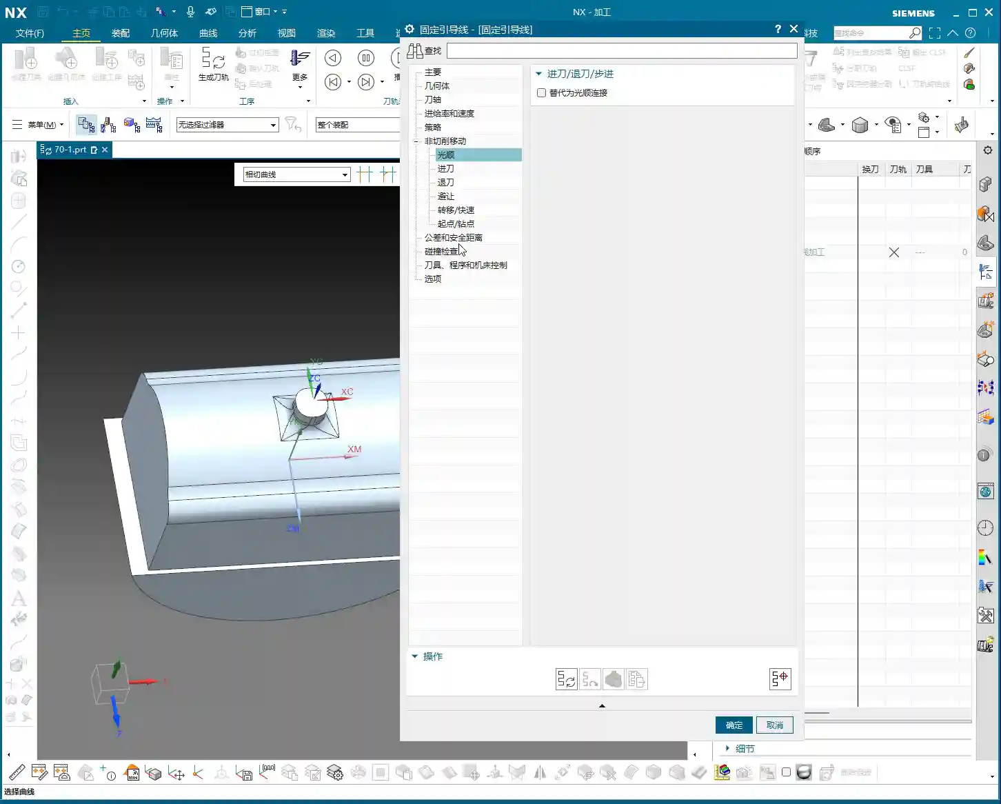
The true power of this ‘Guiding Curve Machining’ command began to emerge with Siemens NX 12.0; it wasn’t available in earlier versions. Its biggest change is the interface. Now, if you open this command in Siemens NX 1980 or higher, you’ll find its parameter interface is different from before; many options have moved to a sidebar, making it look cleaner. But let me emphasize: What if the interface changed? The core parameters and underlying algorithms remain the same! So, when you’re learning, just grasp the core logic; don’t get bogged down by minor interface changes. Personally, I prefer the higher version interface; it’s more efficient to operate.
Practical Essentials: Machining Workflow and Key Settings
Step One: Coordinate System Setup and Workpiece Fixturing
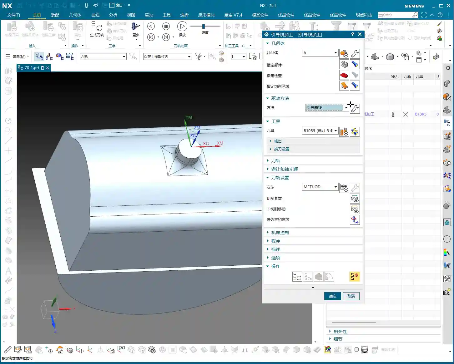
Standard procedure: before you start working, the Work Coordinate System (WCS) must be correctly oriented. You can place it anywhere, as long as you’ve clearly defined the directions of the X, Y, and Z axes. Remember, for 3-axis machining, the tool axis direction is generally fixed, so establish your WCS first to avoid issues later. It’s the same principle as drafting: a shaky foundation leads to collapse!

Tool Selection and Machining Area: The Foundation of Finishing Passes
Next, select your tool. For finishing passes, you typically use a ball end mill. The tool diameter will depend on the fillet radius of your part and the required accuracy. Then, select the area you intend to machine – it could be a single face or multiple faces. Don’t just rely on standard tools from the library; sometimes, for optimal machining efficiency and surface quality, I’ll even grind a custom tool myself. That’s not something you learn from textbooks; it comes purely from experience.

One more thing to note: options like tool axis control (e.g., ‘Axis and Necessary’) are generally not used in 3-axis machining; those are for 5-axis operations. Leave them alone for now, or you’ll just get yourself confused.

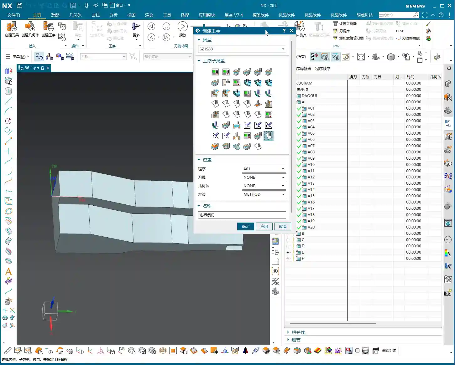
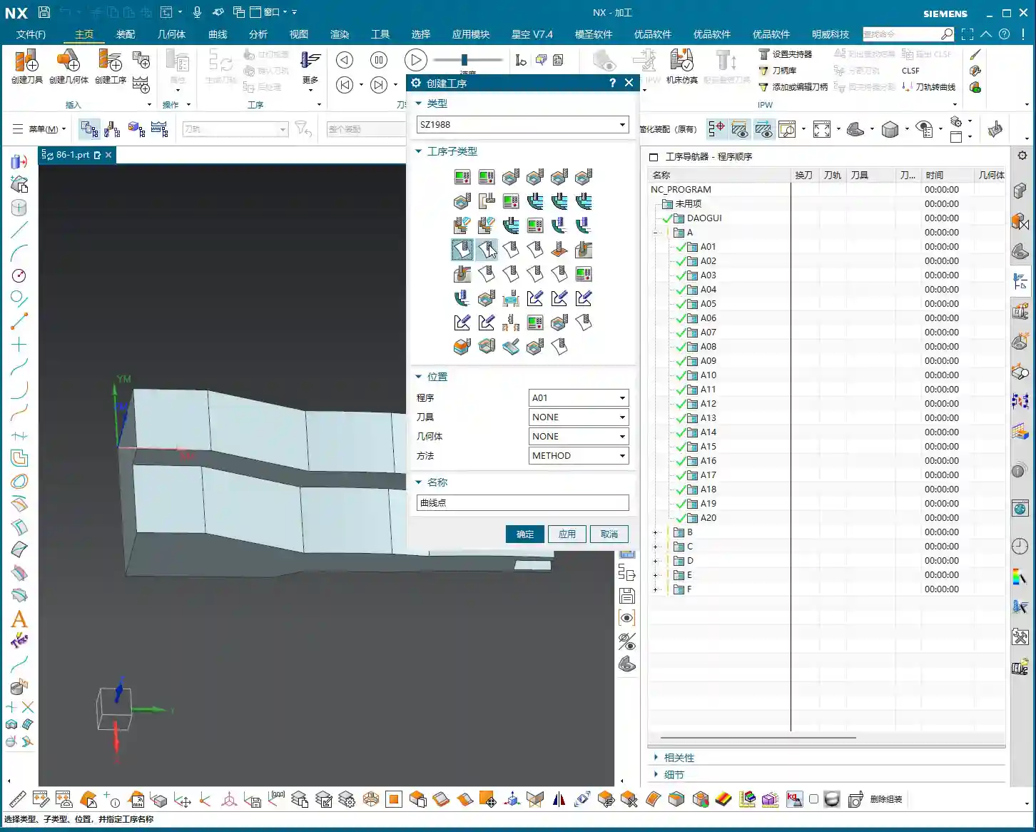
Mode Type: Understanding the ‘Deformed’ Selection and Its Function
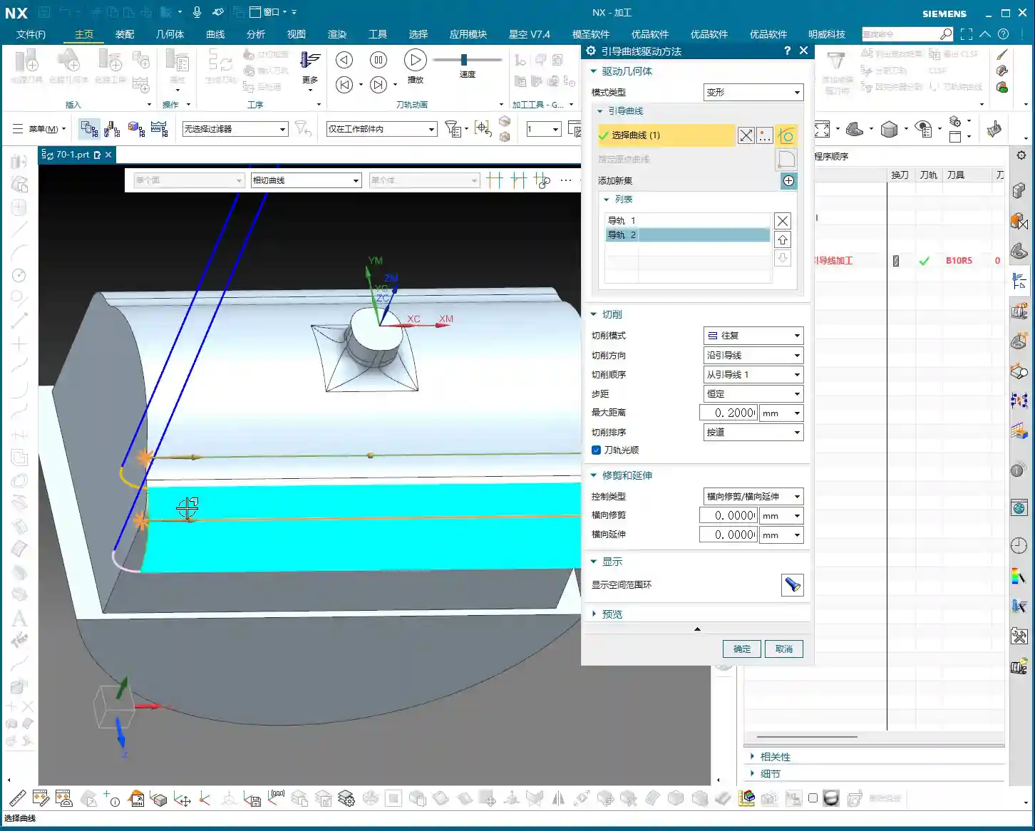
Here’s the critical part! In the parameter settings for ‘Guiding Curve Machining,’ there’s an option called ‘Mode Type.’ Click the ‘wrench’ icon next to it (which is the ‘Edit’ button), and you’ll see several modes. The most commonly used are ‘Deformed’ and ‘Constant Offset.’ Today, we’ll focus on ‘Deformed’ as an example.


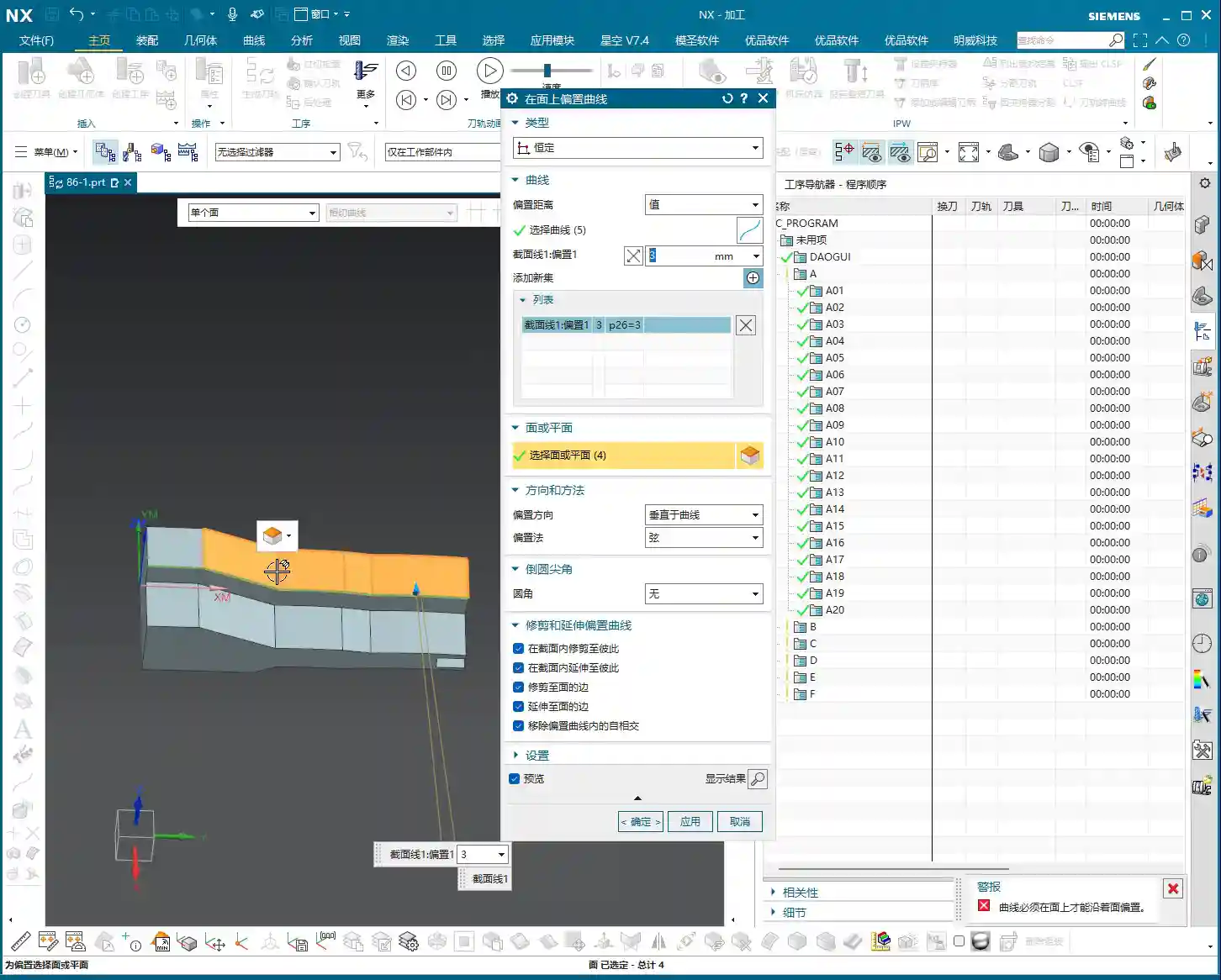
The ‘Deformed’ mode has its own peculiarities; it requires you to select two guiding curves. These two curves act like a ‘track’ for the tool; the tool will operate between them, forming the machining path. This is somewhat similar to selecting two boundary lines when we learned ‘Planar Profile Milling,’ both serving to define the tool’s range of motion.

Master Wang’s Secret Techniques: The Mysteries of Guiding Curve Selection and Direction Control
Selecting Guiding Curves: Where from, where to?
Selecting guiding curves is straightforward, just like selecting wireframe geometry. First, click the initial curve, then click ‘Add New Geometry’ or simply press the middle mouse button, and then select the second curve. These two curves can be closed or open, as long as they define your desired machining area.


However, there’s a crucial detail here, and it’s where many newcomers stumble.
🚨[Pitfall Alert] The Iron Rule of Direction: Guiding Curve Arrows MUST Match!🚨
After you select two guiding curves, you’ll see a small arrow on each curve. This arrow indicates the curve’s direction. Listen carefully: the arrow directions of these two guiding curves must, and can only, be consistent! They either both point in one direction or both point in the other. Absolutely never one left, one right!

I’ve seen too many newcomers fail to pay attention to this when selecting curves, resulting in toolpaths that are either chaotic or immediately trigger errors. Sometimes, even the software simulation looks fine, but the moment you put it on the machine, the cutting sparks look wrong, the part precision is way off, or it even experiences tool deflection and becomes scrap! This is no joke; one wrong direction, and your whole day’s work is wasted, with costs pouring out! If you find the arrow directions inconsistent, simply right-click the curve and select ‘Reverse’; it’s quite simple.
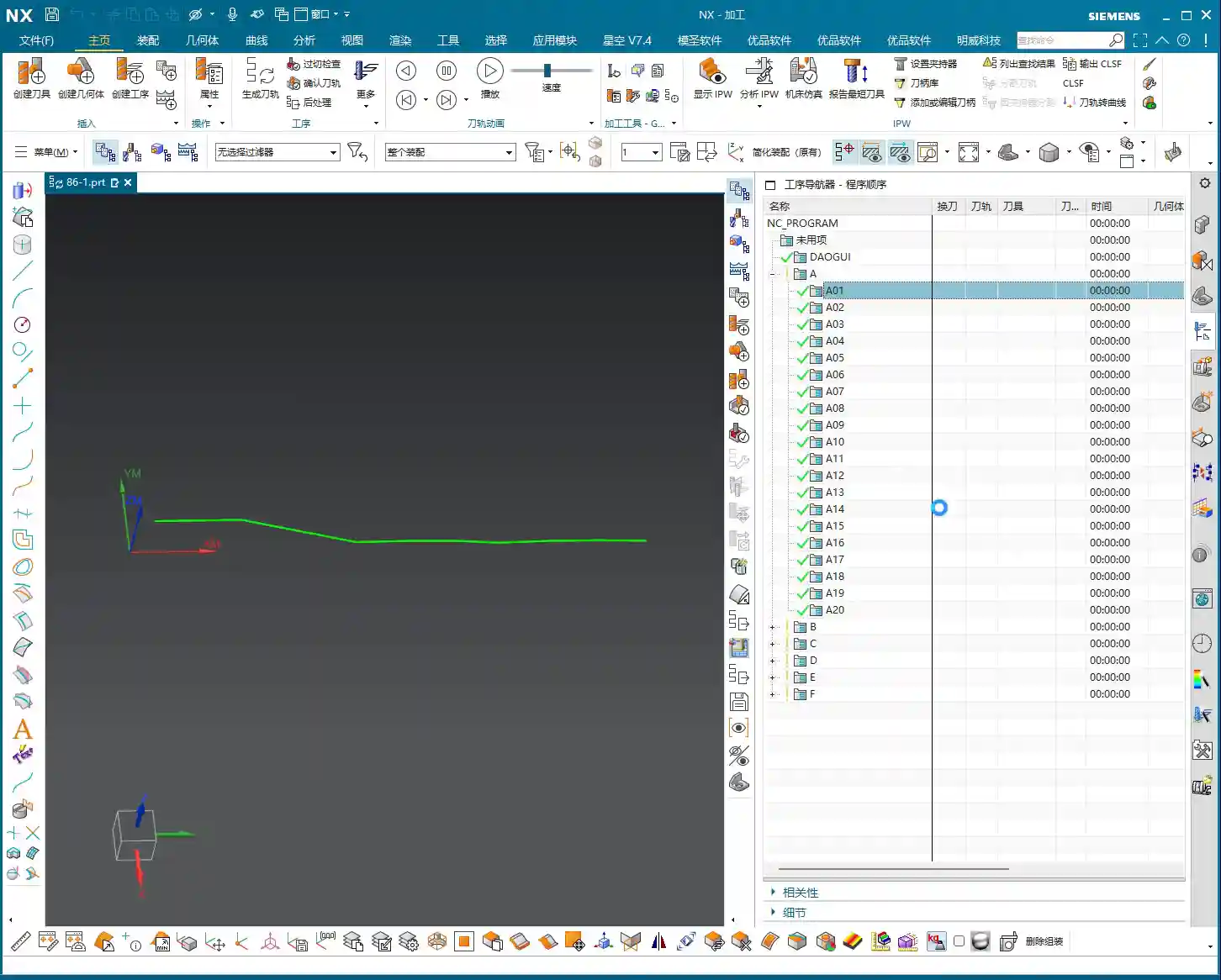
Impact of Different Guiding Curve Selections on Toolpath Direction
The most powerful aspect of this ‘Deformed’ mode is that your chosen guiding curves directly determine the toolpath direction. This is crucial in practice for controlling machining patterns, preventing thermal deformation, and even for fine error compensation!
-
Case One: Horizontal Guiding Curves, Vertical Machining.
If your selected two guiding curves are two parallel horizontal lines on the upper part of the workpiece (e.g., the upper and lower edges of a curved surface), then the generated toolpath will machine from top to bottom, or bottom to top, along a direction perpendicular to the guiding curves. This is like using a roller to paint a wall from top to bottom.
-
Case Two: Vertical Guiding Curves, Horizontal Machining.
Conversely, if your selected two guiding curves are two parallel vertical lines on the sides of the workpiece (e.g., the left and right edges of a elongated feature), then the generated toolpath will machine from left to right, or right to left, along a direction parallel to the guiding curves. This is like using a roller to paint a wall from left to right.
See that? The choice of guiding curves dictates your tool’s cutting direction! This is especially crucial during finishing passes. For instance, some materials, like titanium alloys or high-temperature nickel-based alloys, are highly sensitive to cutting direction and cutting forces. If the direction is incorrect, it can easily lead to work hardening or thermal deformation. By precisely selecting the guiding curves, you gain control over the tool’s path, bypassing the material’s ‘temperament’ and ensuring part quality and accuracy. What’s more, even when facing minute machine precision errors of around ±0.005mm (approx. 0.0002 inch), I resolve them by adjusting guiding curves and implementing process compensation – now that’s true expertise!
So, practice frequently, generate toolpaths using different guiding curve combinations, and observe the variations. Gradually, you’ll grasp the subtleties. This is far more useful than simply memorizing theoretical formulas!
Summary: Pitfall Avoidance Guide
- Mode Type Selection: For machining complex surfaces, especially when toolpath direction control is critical, prioritize ‘Deformed’ mode or ‘Constant Offset’ mode.
- Two Guiding Curves Required: ‘Deformed’ mode necessitates selecting two guiding curves, which define the tool’s operating range.
- The Iron Rule of Arrow Direction: Regardless, the arrow directions of both guiding curves must be consistent! This is crucial for correct toolpaths and avoiding scrapped parts. Otherwise, the toolpath will be chaotic, cutting will be unstable, and accuracy will be completely compromised.
- Toolpath Direction Control: By selecting guiding curves in different orientations, you can precisely control the tool’s cutting direction. This is vital when dealing with material characteristics, surface finish, and preventing deformation.
- Software Version Differences: While interfaces may differ between older and newer versions, core parameters and functionalities remain constant. Learn to apply knowledge broadly and grasp the underlying logic.
Alright, that’s all for today. Practice and experiment a lot; you’ve got to get hands-on with these machines; you won’t learn by just watching. Next time, we’ll discuss other practical tips. See you then!
[EXCERPT]: Master Wang guides you through practical Siemens NX Guiding Curve Machining, focusing on how to select guiding curves in ‘Deformed Mode.’ Emphasizes that guiding curve arrow directions must be consistent to avoid chaotic toolpaths and scrap. Reveals the secret to controlling toolpath direction via guiding curves, solving complex surface machining challenges, enhancing machining accuracy and efficiency, and preventing thermal deformation.
👤 About the Author:
The author is a veteran CNC machining professional with 15 years of industry experience, specializing in UG NX programming. This article is an original work representing personal practical insights.
⚠️ Copyright Notice: Unauthorized reproduction or distribution without prior communication is strictly prohibited.