📝 Key Takeaways: Engineer Wang provides expert insight into core parameters for NX Deep Contour Milling: Merge Distance to control tool lifts, Minimum Cut Length to prevent inefficient micro-cuts, and a multi-layered Depth Layer strategy for fine-tuned machining. This guide will help you optimize your toolpaths and boost machining efficiency.
Hello everyone, this is Lao Wang, Engineer Wang. Today, let’s continue to discuss those seemingly minor parameters in Siemens NX that actually dictate your machining efficiency and part quality. Listen up, these are practical experiences you won’t find in textbooks.
I. Merge Distance: Connecting Toolpaths, Reducing Idle Moves
We’ve discussed “Merge Distance” before in other operations, like DB-type machining and Planar Profile Milling. Simply put, it controls whether the tool will lift and rapid traverse or remain engaged and connect between different cutting regions.
Practical Example: Deciding Between Tool Lifts and Continuous Motion
For instance, imagine you’re machining a part with an empty space in the middle, or a 5 mm gap between two cutting regions. If you set the Merge Distance to 10 mm, Siemens NX will consider these two areas connected because 10 mm is greater than the 5 mm gap. The tool will then move directly across without lifting. The machining path will be continuous.
However, if you set the Merge Distance to 1 mm, NX will recognize that 1 mm is much smaller than the 5 mm gap, indicating a definite need for a tool lift. In this scenario, you’ll see the tool rapidly lift, then move to the next cutting point before re-engaging. This is what we call a “tool lift” or “rapid traverse,” which is represented by blue rapid move lines (G00) in the program.
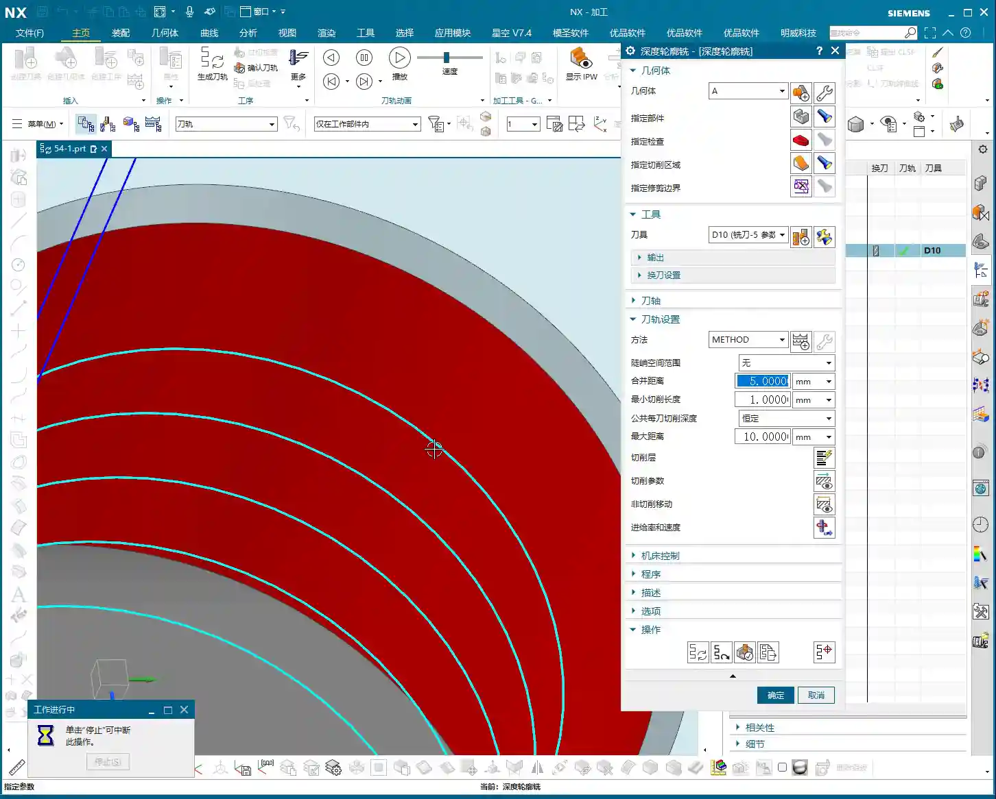
So, this parameter gives you a choice: if you want the tool to maintain continuous motion to avoid unnecessary tool lift and plunge times, set it larger. If you prefer explicit tool lifts for clearer path segmentation, set it smaller. The specific value depends on your part’s features and your efficiency requirements. However, if your part is a fully continuous circle or any other closed, continuous shape, then “Merge Distance” becomes irrelevant, as there are no gaps to “merge.” You can simply ignore it.

II. Minimum Cut Length: Avoiding Short, Inefficient Paths
The “Minimum Cut Length” parameter, as its name suggests, controls the shortest distance the tool will machine. In complex contours, Siemens NX sometimes generates very short cutting paths, perhaps just a few tenths of a millimeter. These short paths are inefficient on a real machine, prone to chatter, and can accelerate tool wear.
Practical Example: Eliminating Ineffective Micro-Cuts
If your Minimum Cut Length defaults to 1 mm, Siemens NX will ignore all cutting paths shorter than 1 mm. This effectively eliminates those “junk” micro-cuts. The tool will only execute a cut when its length meets or exceeds your set value. This is beneficial for maintaining stable toolpaths, reducing unnecessary tool wear, and improving overall efficiency.
Typically, the default 1 mm is sufficient. In my years of experience, I rarely change this parameter. It primarily addresses fragmented geometric features, helping to keep the toolpath “cleaner.” For these less common scenarios, it’s good to simply be aware that this function exists.

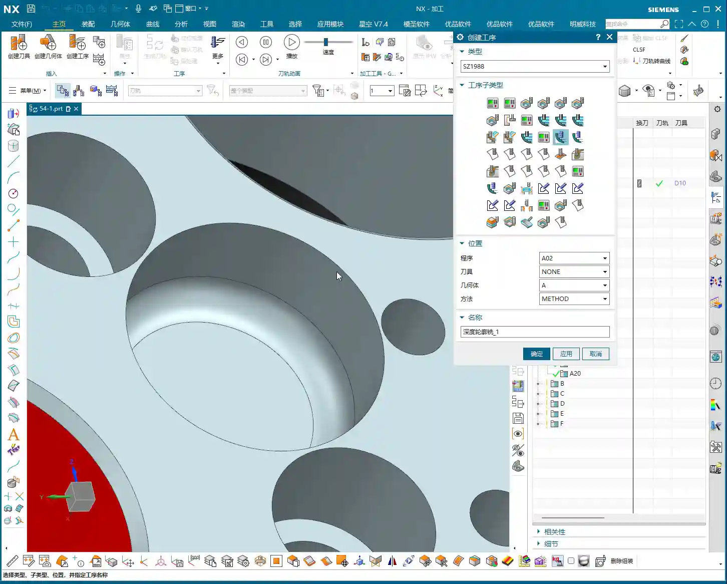
III. Depth Layers: Fine-tuned Control for Deep Machining
Alright, here’s the main event. These “Depth Layers” are one of the core elements in Deep Contour Milling, something I’ve emphasized repeatedly in Cavity Milling. Frankly, how well you program in Siemens NX and how optimized your toolpaths are largely depend on your understanding and application of “Depth Layers.”
Depth Layers Basics: Why Only One Layer?
When you open “Depth Layers,” do you find it defaults to “One Layer”? Don’t be surprised, it’s completely normal. This is because there might only be a single flat area requiring machining between the tool and the part, or the system automatically determines that only one depth layer is needed to achieve the goal. For example, if you’re simply side milling a straight wall, one depth layer is sufficient.

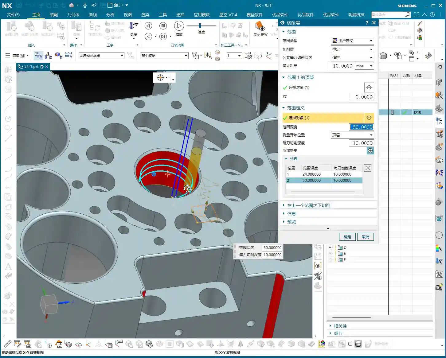
Top Face and Bottom Face: Controlling the Start and End of the Cut
The “Top Face” and “Bottom Face” options are used to precisely define the start and end positions of your cut. Whichever face you select, the tool will begin or end its deep machining operation from that face. For example, if you select the part’s top face as the “Top Face,” the tool will start its downward cutting motion from there.
Another example: for a 48 mm deep circular hole, if you set the “Bottom Face” to Z=-20 mm, the tool will only machine to that depth, effectively machining half the hole. This is extremely useful in practical machining, for instance, if you only want to machine a specific region or if you’re machining in stages.
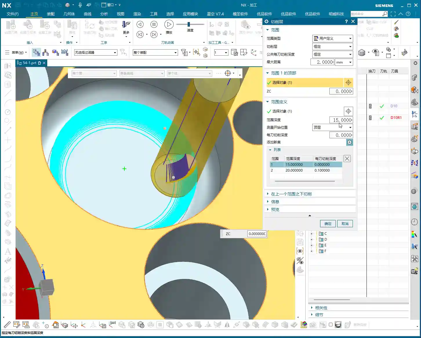
Multi-Layer Depth of Cut: Flexible for Complex Geometries
The most powerful aspect of “Depth Layers” is the ability to add multiple layers and define a different “Depth of Cut (DOC) per pass” for each. For example, on a part where the first 20 mm is a straight wall and the subsequent 30 mm is a large fillet. For the straight wall section, you can take a deeper cut, say 5 mm DOC per pass. When you reach the fillet, to ensure surface finish, you might need to reduce the DOC per pass to 1 mm or even smaller. This allows for much finer control.
The operation is straightforward: add a new layer, then specify a new Z-axis depth range for this layer, and finally, set an independent Depth of Cut (DOC) per pass for it. This way, the tool can machine with varying depths of cut in different Z-axis regions.
This principle is similar to how we sand a panel: for rough grinding, you remove more material; for fine grinding, you go thinner; and for polishing, you need an even shallower Depth of Cut (DOC). The same logic applies in the software: the closer you get to finishing passes, especially in areas with demanding curved or angled surfaces, the smaller your Depth of Cut (DOC) needs to be, and your Stepover should be adjusted accordingly. Conversely, for straight walls or roughing stages, both Stepover and Depth of Cut (DOC) can be more aggressive, prioritizing efficiency.
Optimization Options and Standard Practices
There’s also an “Optimization” option within “Depth Layers,” which is quite complex and involves strategies for optimizing toolpath connections. We’ll skip that today. Later, when I program a more intricate part, I’ll dedicate a separate lesson to thoroughly explain what this “optimization” means and how to use it to truly boost efficiency.
However, there’s one point I want to emphasize: in Deep Contour Milling, we have a standard practice. Regardless of whether you’re only machining one face, if the part has clear top and bottom faces, we tend to select both of them. Why? This ensures that Siemens NX, when calculating the depth layers, can more accurately capture the part’s overall depth information, leading to more logical toolpaths. While sometimes, if you’re only machining one face, selecting both might not make a difference, cultivating this good habit can prevent many subsequent issues.

Practice, Practice, Practice!
These “Depth Layers” are absolutely critical for us in Siemens NX programming. Not just in Deep Contour Milling, but in Cavity Milling as well. Their utility is immense. So, I highly recommend you all go back and practice. Sketch a few parts with varying depths and shapes, then try using “Depth Layers” to control the Depth of Cut (DOC) for each pass and observe the toolpath changes. Only by hands-on practice and critical thinking can you truly master these practical tips.
Summary: Pitfall Avoidance Guide
1. Merge Distance: Bigger Isn’t Always Better
- Don’t blindly set the Merge Distance to a very large value. While it can reduce tool lifts, if there are obstacles or non-cutting regions in between, it could lead to tool collisions or inefficient cutting.
- Select an appropriate value based on the actual gaps in the workpiece to ensure both efficiency and safety. If the gap contains features like bosses, even if a continuous cut is possible, you must consider whether the tool will interfere with these features.
2. Minimum Cut Length: Be Careful Not to Delete Critical Paths
- The default value of 1 mm is usually sufficient, but if you encounter tiny features that genuinely require machining, and your set Minimum Cut Length is too large, these features might be ignored, leading to incomplete machining.
- For parts with extremely high precision requirements and very small feature sizes, this value might need to be set smaller, but you must balance tool life and machining stability.
3. Depth Layers: Don’t Treat Theory as a Panacea
- Multi-layer Depth of Cut (DOC) offers flexible control, but you must consider material, tooling, and machine rigidity holistically. Not all situations are suitable for large or small depths of cut.
- Newcomers often focus solely on beautiful software simulations, neglecting real-world machining issues like chatter, chip evacuation, and cutting forces. Remember: Don’t just rely on software simulations; observe the cutting sparks, listen to the cutting sound, and feel the machined surface!
- The Z-axis ranges and DOC per pass for multi-layer cutting must be precise, especially for the final finishing pass layers. The depth of cut should be small, and the Stepover should also be fine to ensure surface quality.
- Make it a habit in Deep Contour Milling to always select the workpiece’s top face and bottom face as the boundaries for your depth layers. Even if the current operation doesn’t strictly require it, this provides the system with more comprehensive geometric information, facilitating subsequent adjustments and optimizations.
👤 About the Author:
The author is a veteran CNC machining professional with 15 years of industry experience, specializing in UG NX programming. This article is an original work representing personal practical insights.
⚠️ Copyright Notice: Unauthorized reproduction or distribution without prior communication is strictly prohibited.