📝 Key Takeaways:
Planar Profile Milling: Practical Parameters and Pitfalls
Hello everyone, I’m Master Wang. Last lesson, we covered Planar Milling. T…
Hello everyone, I’m Master Wang. Last lesson, we covered Planar Milling. This time, we’ll continue our discussion and dive into “Planar Profile Milling.” Don’t let the similar name fool you; there’s a lot more to it, especially some practical tricks you won’t find in textbooks. Today, I’ll break it down and explain everything clearly for you.
Command Overview: What Exactly is Planar Profile Milling?
Don’t Get Confused: It’s All About the “Edges and Sides”
Listen up: Planar Profile Milling, as the name suggests, is primarily used for machining the “profiles” or “side walls” of a workpiece. Unlike the broad, aggressive roughing of standard Planar Milling, Planar Profile Milling is more like a precision edge-finishing specialist. It can only follow the contour lines you select, such as the side wall of a slot or the outer edge of a boss.

For example, if you have a small slot, 18 mm wide, and you use a ∅10 tool to mill it, Planar Profile Milling will only follow the two side walls of the slot, finishing them or roughing the side wall stock. It won’t clear out the entire interior of the slot like Planar Milling would. You absolutely *must* distinguish this, otherwise, you’ll make mistakes!

It Can Handle Roughing and Finishing, But Your Approach Must Be Correct
This command isn’t picky; it can be used for roughing the stock on side walls, for a finishing pass on side walls, and even for chamfering. The key is to have the right “approach.” When you want to machine the side of a particular contour, this command comes into play. But remember, its core function is to follow the contour, not for planar Corner Cleanup or floor clearing.
You can think of it as a specialized function within the larger framework of Planar Milling in NX, specifically for machining “boundary walls.” Use it flexibly, and you’ll save a lot of trouble; but use it incorrectly, and you’ll run into big problems.
Core Settings: Part Boundaries and Toolpath Direction

Curve Selection: Order is Key, Never Skip Around
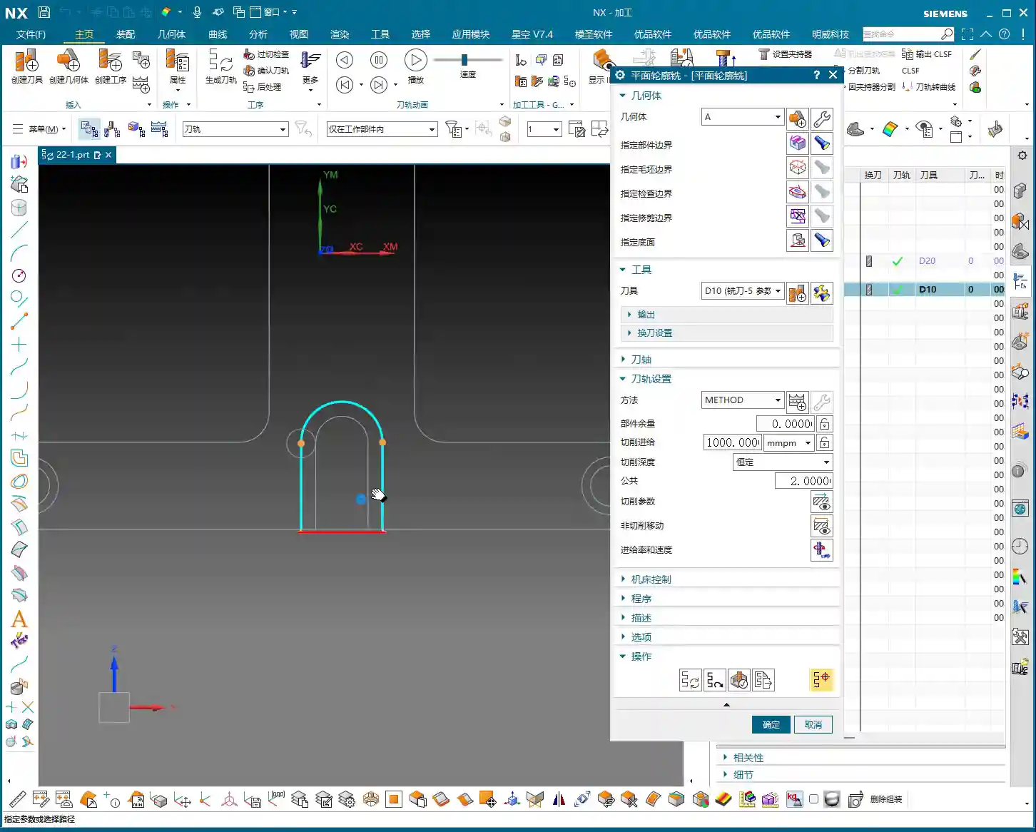
Let’s go straight into the NX interface and select “Planar Profile Milling.” The first step is to “Specify Part Boundaries.” Here, select the “Curve” method, which is the most commonly used.

Listen closely, this is critical! When selecting the curves that form the profile, you must select them sequentially and continuously. For a closed contour, for example, you need to click each segment in order along one direction (clockwise or counter-clockwise). For an open contour, also select them sequentially along the tool’s travel direction.
Remember, never skip around! For instance, if you select one line here, then jump to another line over there, NX will assume you want to connect these two lines for machining, leading to a chaotic toolpath or even an error. This is something textbooks don’t teach, and it’s a common rookie mistake in actual operation!
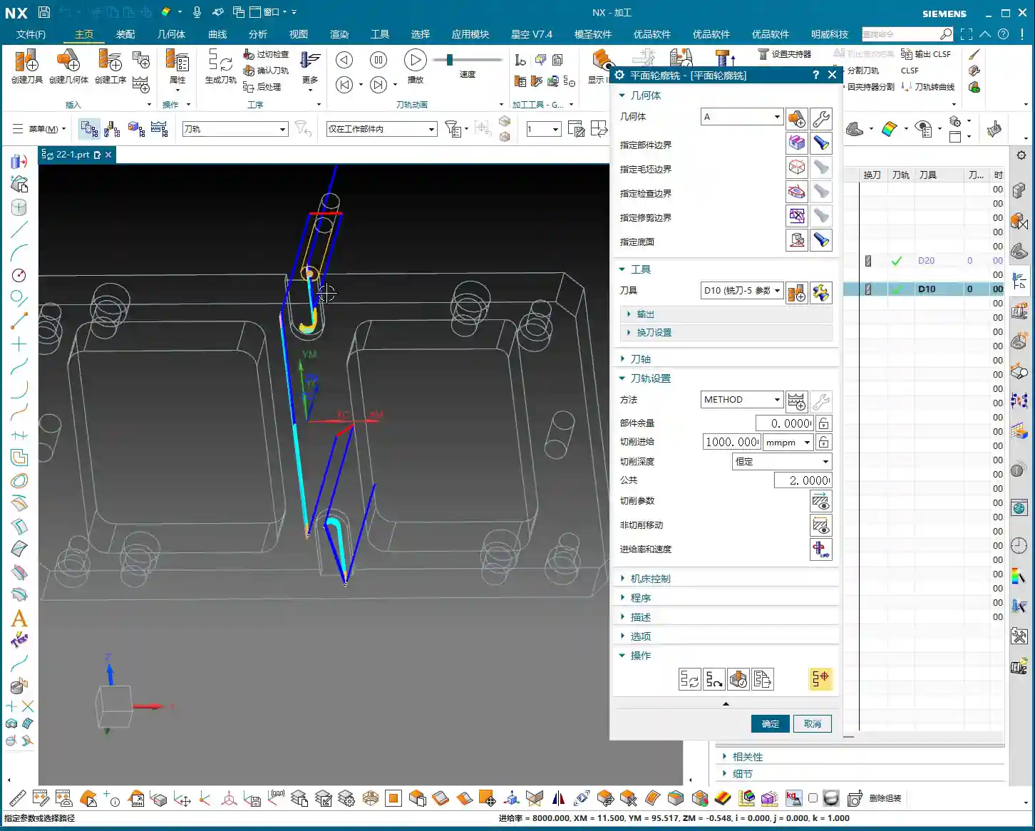
Toolpath Direction: The Small Circle Dictates Inside or Outside!
After selecting the curves, let’s look at the “Tool Side” option. Here you’ll see a small circle, which indicates on which side of the selected curve the tool center will be.
- If the small circle is on the outside, it means the tool will move to the outside of the contour, which will almost certainly cause “overcutting” and scrap your workpiece!
- If the small circle is on the inside, the tool will move to the inside of the contour, which is typically what we want.
Therefore, if you ever notice something off with the toolpath, the first thing to check is whether the “Tool Side” is set to “Left” or “Right.” Based on the geometry you’re actually machining, select the correct direction to ensure the tool is cutting on the inside of the contour.
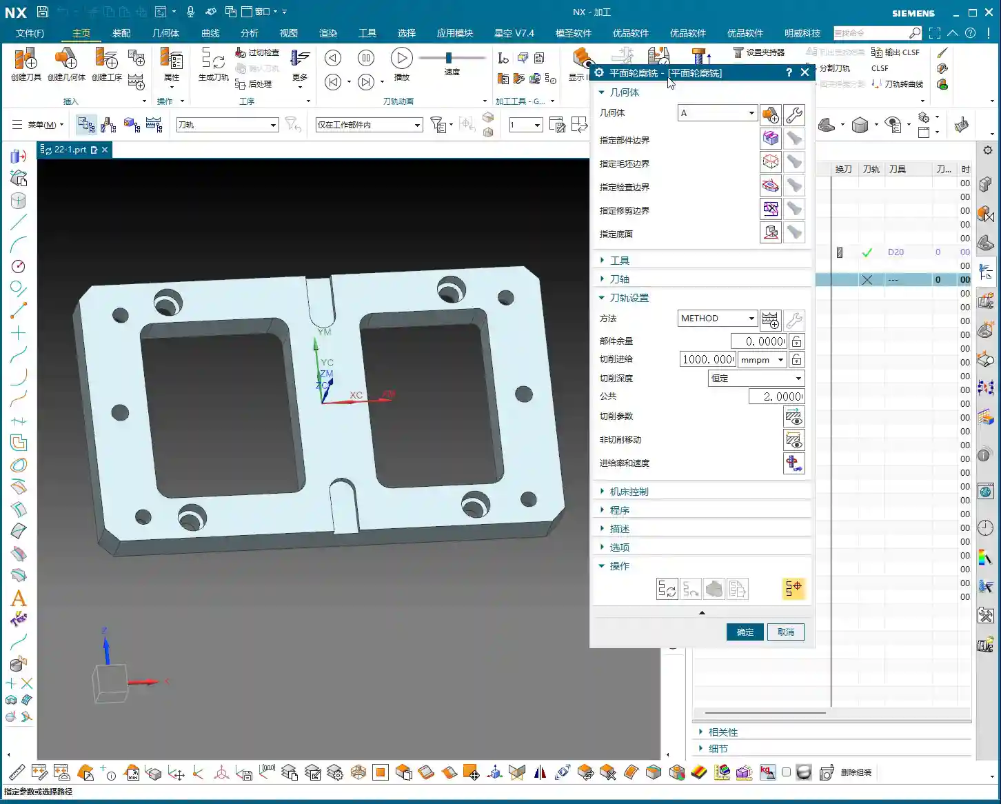
Then, for “Specify Bottom Face,” this is the same as Planar Milling; just select the bottom plane you want to machine, no need to elaborate.

Pitfall Alert: No Software Error Doesn’t Mean No “Scrap”
Let me tell you a plain truth: when generating these contour toolpaths, if you select the wrong “Tool Side,” NX (and many other CAM software packages) won’t necessarily throw an error immediately! It will dutifully generate a toolpath that “runs outwards.” The moment that hits the machine, it’s not “cutting,” it’s “scrapping” the part! At best, you’ll ruin the part; at worst, you’ll damage the tool or even the machine.

So, don’t just rely on software simulation; review the toolpath multiple times, paying close attention to the position of that small circle. “Simulate” with your eyes. Developing this habit can save you significant machining costs and time.
Lead-in/Lead-out Optimization: Say Goodbye to “Plunge-in” and “Air Cutting”

Linear Lead-in/Lead-out: Smooth Engagement, Protect the Tool
With the initial generated toolpath, you might find the tool “plunging” directly into the material, or after finishing one area, it lifts instantly and “jumps” to a distant spot before plunging in again. Such “plunging” and “air cutting” are not only inefficient but also prone to damaging the tool and reducing surface quality.
The solution lies within “Non-Cutting Moves,” specifically under the “Lead-in/Lead-out” options.
- Change the default “Arc” lead-in/lead-out to “Linear,” so the tool enters and exits the cut at a smooth, gradual angle.
- Set the angle typically to around 5 degrees, and the length to 75% of the tool diameter (or adjust according to actual conditions). This way, the tool “slides” in rather than “plunging” in, which benefits both tool life and machining stability.
If multiple cutting layers are needed, this is usually set under “Cutting Depth,” which follows a similar logic to Planar Milling, so I won’t elaborate further here. By adjusting the stepover, for example, by making the tool machine the side wall in three passes, this ensures the proper Depth of Cut (DOC) and reduces the load on each individual pass.

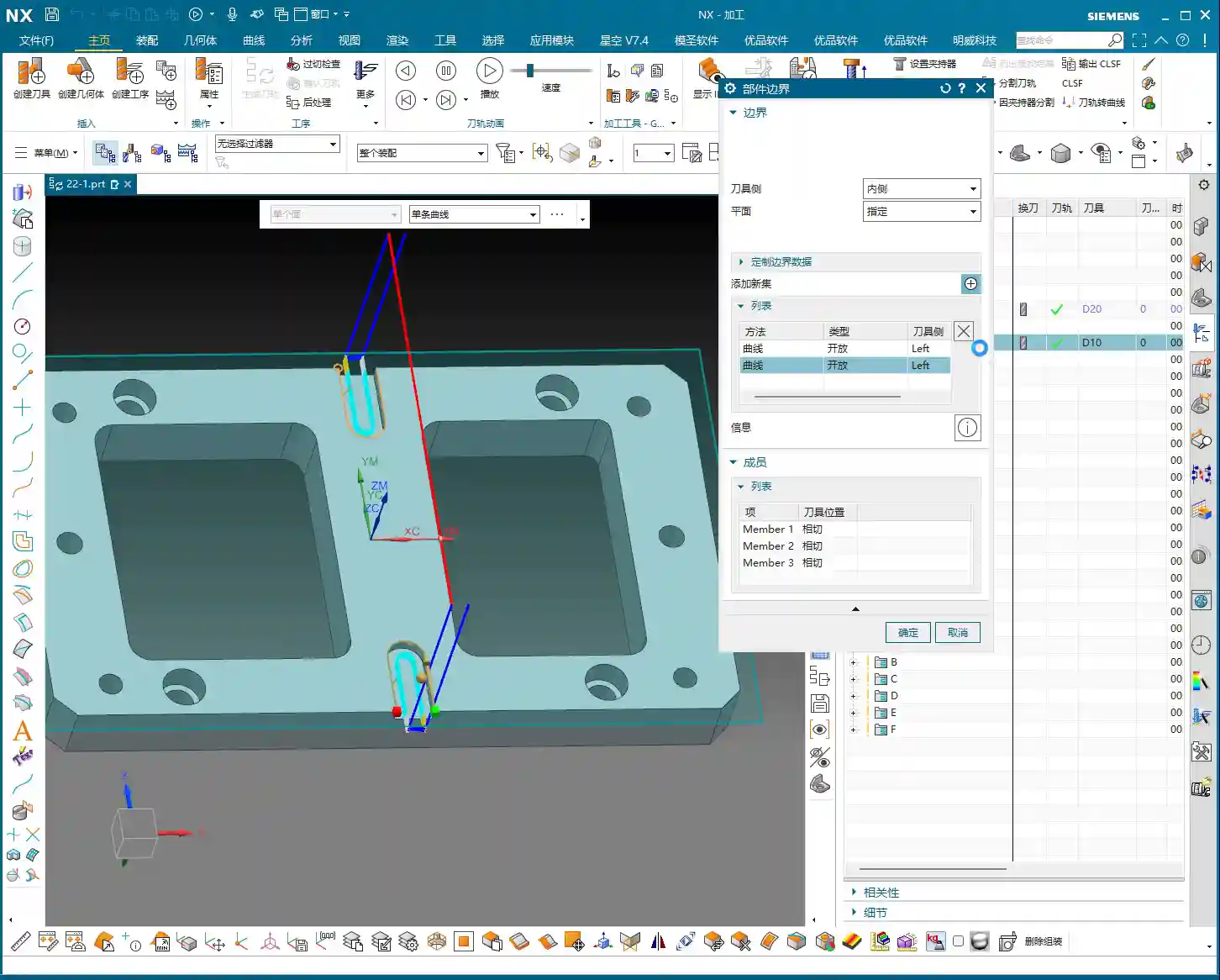
Multi-Region Machining: One Region, One Boundary
Crucial! Add New Boundary or Press Middle Mouse Button
Often, our workpieces have multiple independent contours that need machining. For instance, after milling the inner side wall of one slot, you might want to mill the outer side wall of another boss.
Here’s another common mistake beginners make! If you simply continue selecting new curves, NX will assume you want to “connect” the previously selected boundaries with the newly selected ones. The result will be erratic toolpaths, or they might not generate at all.
The correct procedure is: after you complete the curve selection for one contour region, you must click the “Add New Boundary” button, or, more quickly, press the “middle mouse button” once. This is equivalent to telling the software: “I’ve finished selecting the boundaries for this region; now I want to define a new, independent machining area.”
After adding a new boundary, proceed as described earlier: sequentially select the curves for the new region and check the “Tool Side” direction. This way, different contour regions will generate correct toolpaths independently, without interference. This is much faster and more reliable than having to rework and modify the program afterward.
Summary: Pitfall Avoidance Guide
- Clarify Purpose: Planar Profile Milling is *only* for machining “side walls” or “profiles”; don’t use it to clear out an entire planar area.
- Consecutive Curve Selection: When “Specifying Part Boundaries,” curves within the same region must be selected sequentially and continuously; do not skip selections.
- Check Tool Side: Always observe the position of the small circle to ensure the tool is cutting on the inside (or your desired side) of the contour, preventing overcutting. No software error does *not* mean the toolpath is correct!
- Separate Multi-Regions: When machining multiple unconnected contour regions, after completing the selection for one region, you must click “Add New Boundary” or press the “middle mouse button” to define the boundaries of different regions separately.
- Optimize Lead-in/Lead-out: In “Non-Cutting Moves,” under “Lead-in/Lead-out” settings, change the default arc to linear and adjust the angle and length to achieve smooth tool engagement and reduce tool impact.
- Develop a Checking Habit: After every toolpath generation, simulate and observe repeatedly. Use the experience of a seasoned machinist to judge if the toolpath is reasonable, instead of blindly trusting the software.
Alright, that concludes today’s practical essentials for Planar Profile Milling. These are all experiences I, Master Wang, have distilled from fifteen years in the trenches. Remember them, and you’ll navigate machining with far fewer detours and mistakes. Go ahead, digest this information thoroughly, because practice is where true knowledge is gained!
👤 About the Author:
The author is a veteran CNC machining professional with 15 years of industry experience, specializing in UG NX programming. This article is an original work representing personal practical insights.
⚠️ Copyright Notice: Unauthorized reproduction or distribution without prior communication is strictly prohibited.