📝 Key Takeaways:
NX CNC Machining Practice: Complete Part Simulation
Hello everyone, I’m Engineer Wang. Today, let’s discuss how to streamline the entire…
[VIDEO_HERE]
Hello everyone, I’m Engineer Wang. Today, let’s discuss how to streamline the entire Siemens NX (UG) CNC machining process for a part, from roughing to finishing, and all the way through final simulation and verification. This session marks the final stage of machining for this particular part, focusing on finishing all the top surfaces to complete the job. Listen up, this is all based on real-world experience.
Coordinate System and Stock: Laying a Solid Foundation
First, we need to establish the ground rules. The coordinate system and stock are the foundation of our machining. If the foundation isn’t solid, any structure built on top, no matter how elaborate, will be useless.
Coordinate System Selection and Clamping Considerations
For the final operations on this part, I’ve positioned the Work Coordinate System (WCS) at the front clamping location. Why there? Because this most accurately reflects the actual clamping setup and makes it easier to observe the toolpaths. X-axis centered, Y-axis to the front, Z-axis at the bottom face – this is the most reliable approach. Don’t just think about a pretty model; consider if the part can be securely clamped on the machine and if there will be any interference.
Stock Size Setting is Critical
When creating the program group, select a milling type, for instance, “Face Milling”. Initially, I tried a stock size of 200 mm. After some consideration, it felt a bit small, so to be safe, I directly set it to 250 mm. Better to be a bit larger than too small; leave sufficient material for flexibility. During the later finishing passes, if the stock size is set improperly, “undercutting” or “overcutting” issues can easily occur, which always leads to rework, wasting both time and effort.

Roughing Strategy: Aggressive Cuts, Efficiency is King
Roughing emphasizes “speed, precision, and aggressiveness” to remove most of the material, easing the burden for subsequent finishing passes. However, speed doesn’t equate to recklessness; you need to be precise with tool selection, parameters, and toolpaths.
Tool Selection and Machining Area Division
For the upper section of this part, we have two approaches. The first is to perform roughing with a D10 or D16 tool to remove bulk material, then switch to a D10 tool for a finishing pass. The second is to use a D12 tool directly to complete the job in a single pass. I generally prefer the second option, as it avoids tool changes and, provided the tool’s rigidity is sufficient, it’s more efficient to complete in one shot.
Cavity Milling and Bottom Face Roughing Parameter Settings
We’ll use Cavity Milling for side wall machining. Select a D12 tool, and set the single Depth of Cut (DOC) (step) to 0.2 mm. This parameter needs to be adjusted based on the material and machine rigidity; don’t just blindly chase speed. For the side walls, we’ll initially leave 2 mm of stock, and also leave 2 mm of stock on the bottom face. Why? Because the bottom face will be finished later with a smaller tool; leaving a larger allowance now prevents interference with the larger tool. Cutting layer settings are crucial; don’t let the tool plunge directly to the bottom; leave enough space for the subsequent finishing pass.
For bottom face roughing, we’ll use a D10 tool. The single Depth of Cut (DOC) will still be 2 mm, and the bottom face stock allowance will be 0.15 mm. The purpose of roughing is to remove the bulk material, leaving just a small allowance for the finishing pass.

Avoid Air Cuts and Optimize Toolpaths
No matter how powerful NX’s simulation is, it cannot replace your judgment of actual cutting conditions. Air cuts not only waste time but can also lead to machine chatter, affecting machining quality. When programming, always consider how to make toolpaths more compact and reduce unproductive travel. For instance, the stock allowance set earlier for the bottom face is specifically to prevent the large tool from making ineffective cuts, or it’s a deliberate arrangement for the subsequent finishing pass.
Finishing Passes: Details Determine Success
Roughing removes the bulk material; finishing is about refining the contours. At this stage, toolpaths, stock control, and cutting parameters must be meticulous; there’s no room for error.
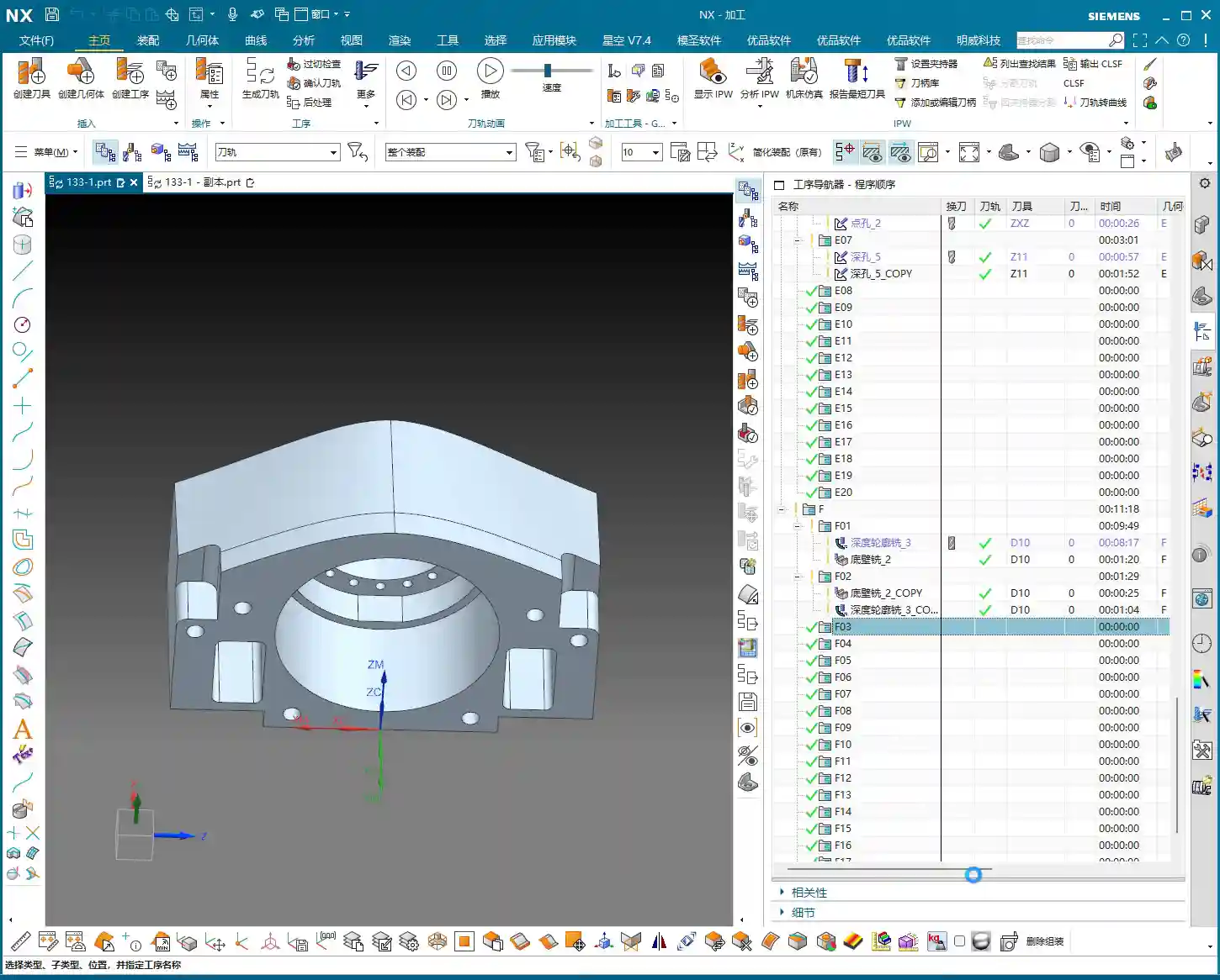
Implementing Bottom Face and Side Wall Finishing Passes
After completing bottom face roughing, simply copy that operation. Set the bottom face stock allowance to 0, and that becomes your finishing pass. The same applies to the side walls: copy the roughing operation and set the side wall stock allowance to 0. Remember to change the cutting layers to automatic, allowing the system to determine them. At this point, you’ll need to observe the cutting sparks and listen to the sound. If something sounds off, stop immediately and check.

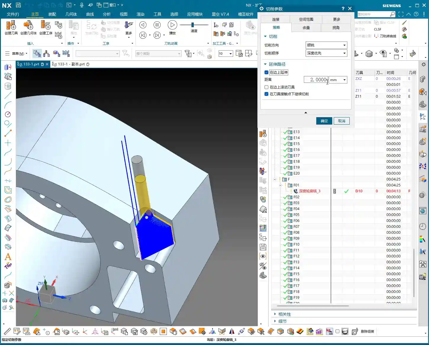
Flexible Use of Tool Extension
When making a finishing pass, if you feel the tool isn’t cleanly cutting the edges, you can appropriately add a bit of tool extension, for example, 2 mm. This ensures the tool completely exits the workpiece, preventing residual material. But don’t extend blindly; excessive extension could lead to collision with the fixturing or moving to an unintended area, causing an accident.
Complex Area Machining: Ball-End Mills to Tackle Tricky Corners
For areas with curved surfaces or fillets, you must use Area Milling. We’ll select a ball-end mill, select the entire area directly, and perform a finishing pass. Since roughing has already been performed, there’s no need to leave any stock allowance here; go straight to the final depth. The advantage of a ball-end mill is its ability to handle various complex surfaces and transitions, resulting in a smoother part surface.
Precise Control of Cutting Layers to Avoid Recutting
When performing Area Milling, a common issue is frequent air cuts. NX allows you to solve this by controlling the cutting layers. For instance, you can specify the tool to start machining from the side wall of the part, rather than plunging from thin air. This not only reduces idle travel time but also prevents secondary cutting of already machined surfaces, ensuring surface quality.

Simulation Verification: Seeing is Believing, Mitigating Risks
Once programming is complete, the most important step is simulation. Don’t think NX simulation is just for show; it’s your “safety fuse” for discovering potential issues and preventing machine crashes!
Critical Precaution Before Simulation
Listen up, this is a hard-learned lesson from Engineer Wang: Before performing any simulation, always save your program! Although NX’s simulation is powerful, it can sometimes freeze or even crash when encountering complex toolpaths or model issues. If you haven’t saved at that point, all your previous effort will be wasted.
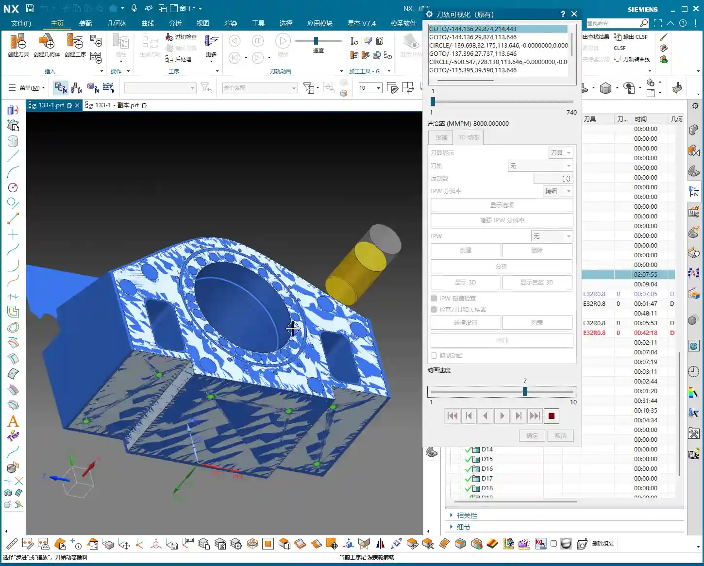
Key Points to Observe During Simulation
During simulation, don’t just watch how fast the tool moves; observe carefully:
- Are there any overcuts or undercuts? Check if the machined model surface is smooth, if there’s any excess material (undercut), or if areas that shouldn’t be cut have been removed (overcut).
- Is there any tool-fixturing interference? This is a critical mistake! The purpose of simulation is to detect interference points beforehand to prevent machine crashes.
- Is the toolpath logical and efficient? Are there excessive air cuts? Are entry and exit moves smooth? These all relate to machining efficiency and surface quality.
Although this part appears simple, we actually divide it into six operations: roughing, semi-finishing, followed by heat treatment, and then the final finishing passes. Don’t underestimate these steps; not one can be skipped, and each has its own rationale.
“Complex” Operation Planning for Seemingly Simple Parts
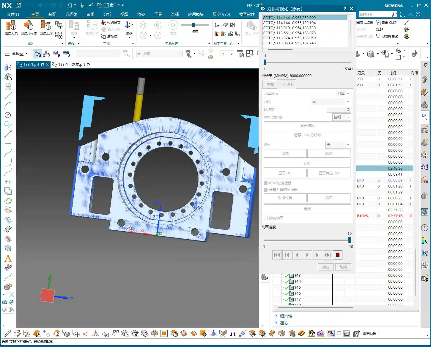
In the simulation, we will see:
- First, roughing down to the bottom face to remove the bulk of the material.
- Then, preparation for finishing (semi-finishing), at which point heat treatment may still be required, so some stock allowance is left.
- Next is drilling.
- Finally, the final finishing and finish cuts, machining all surfaces to the required dimensions.
Although some minor display issues may occur during simulation, such as lag or incomplete graphic rendering, as long as the core toolpaths and cutting actions are correct, these are usually not major problems and can be ignored. What’s important is that through simulation, we can ensure all machining steps and toolpaths meet requirements and that no mishaps occur during actual machining.
Summary: Pitfall Avoidance Guide
- Secure Coordinate System Setup: Always prioritize actual clamping for stable and precise machining.
- Sufficient Stock Size Allowance: Better to be slightly oversized than undersized, leaving room for subsequent operations and avoiding undercuts.
- Roughing for Efficiency, Finishing for Detail: Proper tool and parameter selection, precise stock allowance control.
- Eliminate Air Cuts: Optimize toolpaths and precisely control cutting layers to reduce unproductive travel and enhance efficiency.
- Ball-End Mills are Key for Surface Machining: Utilize ball-end mills effectively for complex contours, but pay attention to cutting layer control.
- Always Save Before Simulation: This is your last line of defense for protecting your work!
- Simulation is Not Just for Show, but for Insight: Pay attention to overcuts, undercuts, interference, and toolpath rationality.
- Multi-Operation Processes are Standard: Many seemingly simple parts inevitably require multiple operations to ensure quality, especially those involving heat treatment.
That concludes this discussion. Remember, textbook theory is foundational, but real-world experience on the shop floor is true gold. Observe more, think more, and get hands-on experience, and you’ll become a true master!
👤 About the Author:
The author is a veteran CNC machining professional with 15 years of industry experience, specializing in UG NX programming. This article is an original work representing personal practical insights.
⚠️ Copyright Notice: Unauthorized reproduction or distribution without prior communication is strictly prohibited.