📝 Key Takeaways: Master Wang guides you step-by-step through practical techniques for Corner Cleanup Regions in Siemens NX. Learn to create, split, merge, and delete regions, with an in-depth analysis of how to leverage these functions to optimize toolpaths, reduce air cuts, and prevent chatter. Master practical machine operation and efficiency-boosting secrets not found in textbooks!
Listen up, everyone, this is Master Wang. Today, we’re going to talk about an incredibly useful function in Siemens NX: the Corner Cleanup Region. Textbooks might only gloss over this, but in actual machining, mastering it is key to clean work and high efficiency. Don’t just rely on software simulations; often, the cutting sparks and machine chatter are your real teachers.
Corner Cleanup Regions: More than just a boundary—A “scalpel” for finishing
What is a Corner Cleanup Region?
Simply put, a Corner Cleanup Region allows you to specify a reference tool, and the software automatically identifies areas that this reference tool cannot machine. Small radii, narrow slots, and deep pockets—areas a large tool can’t access—require a smaller tool for cleanup. This is Corner Cleanup, and a Corner Cleanup Region refers to these areas that need to be machined by a smaller tool. The software will highlight these areas with yellow arrows or a colored region, indicating, “My large tool didn’t fully clean this spot; a follow-up pass is needed.”
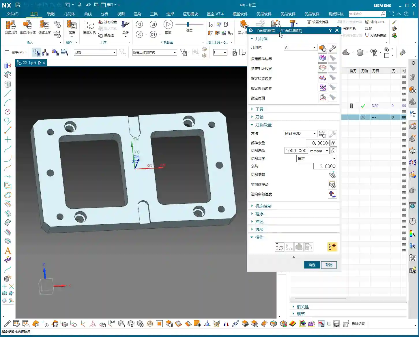
When we talked about specifying part features, tangent faces and selected faces were foundational. Corner Cleanup Regions are similar; you first need to define your machining scope, for example, by right-clicking and selecting “Tangent Faces” to quickly select surfaces, or by direct selection. There’s not much new here; it’s similar to the selection methods we discussed for Area Milling, all aimed at defining your stock and part boundaries.
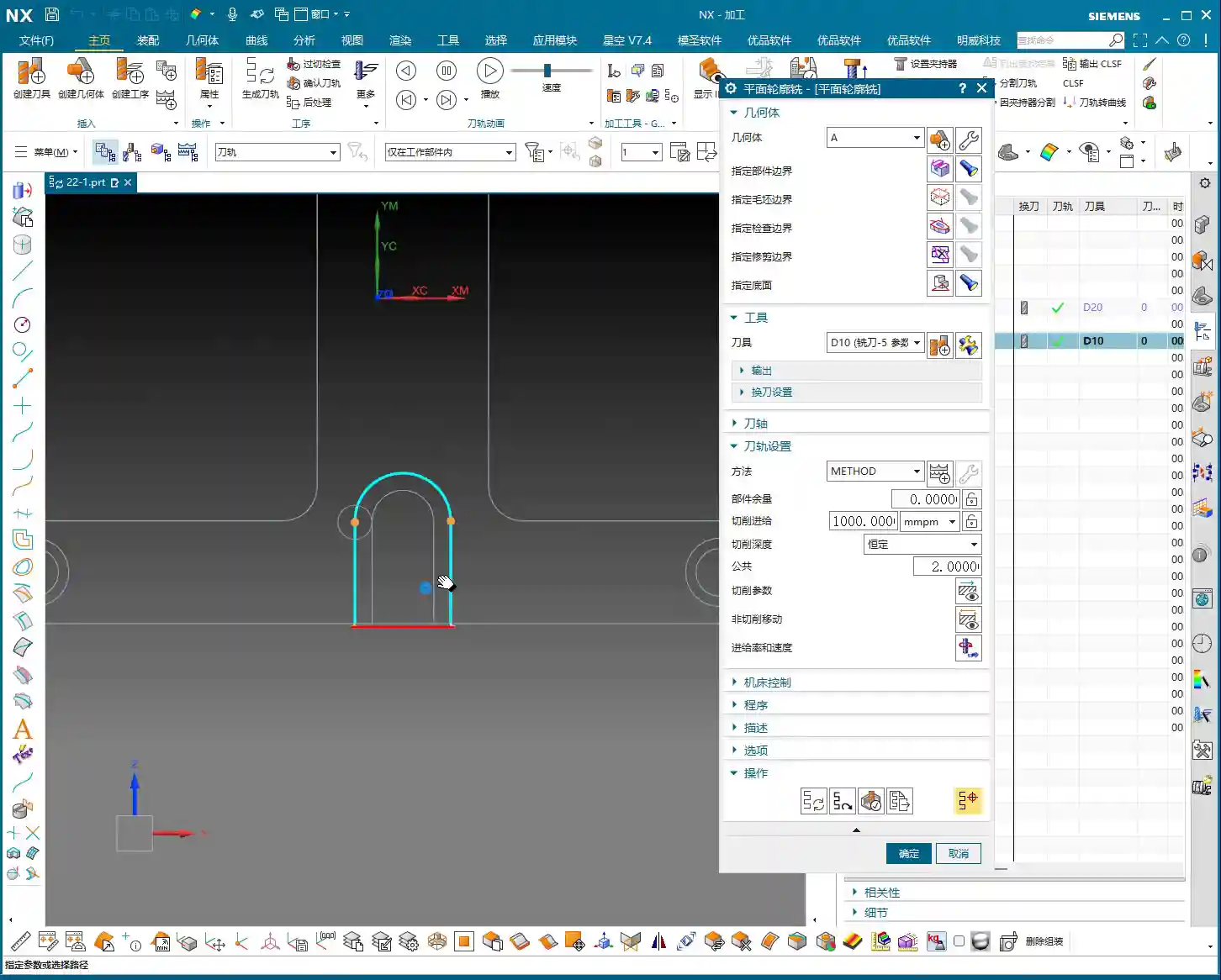
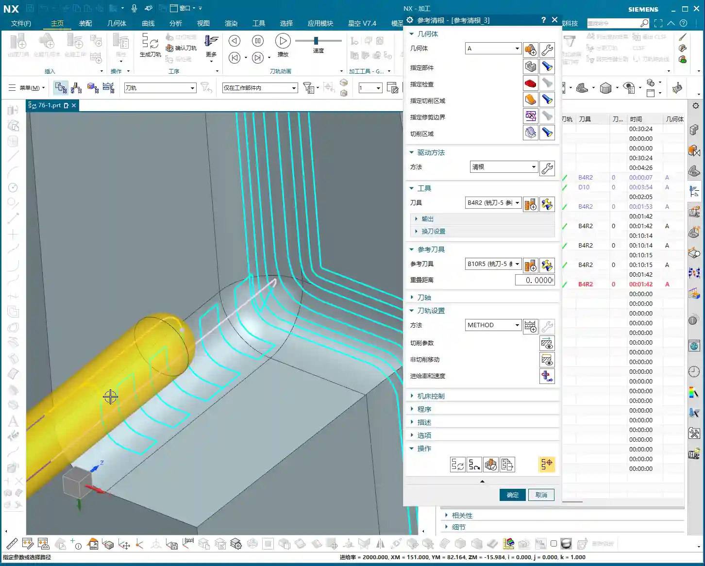
Process Parameter Settings (using a reference tool as an example)
For this demonstration, we’ll still use that 4mm flat end mill as the cleanup tool. But where’s the key? It’s in the parameter settings! Especially the Stepover. For example, I’ll increase the Stepover for zig-zag depth milling a bit from the default, setting it to 0.5mm. Sometimes, to make the effect more apparent, I’ll deliberately set it to 1mm or even 2mm. The Stepover setting directly impacts your machining efficiency and surface finish; you must be aware of this. Set it too small, machining time increases, and tool wear accelerates; set it too large, machining quality might not meet specifications, and it could even lead to Chatter.

Creating and Managing Corner Cleanup Region Lists
Why Create a Region List?
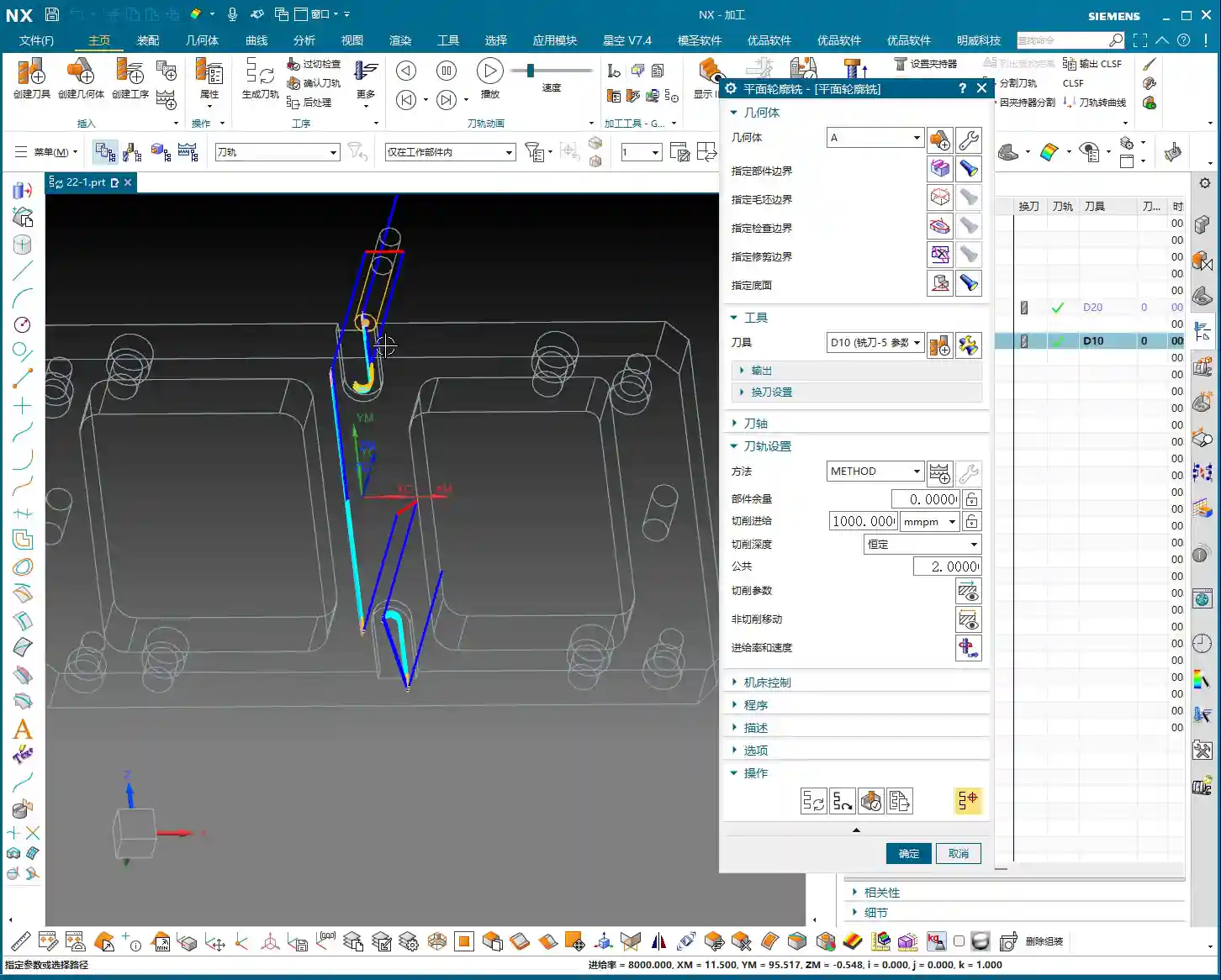
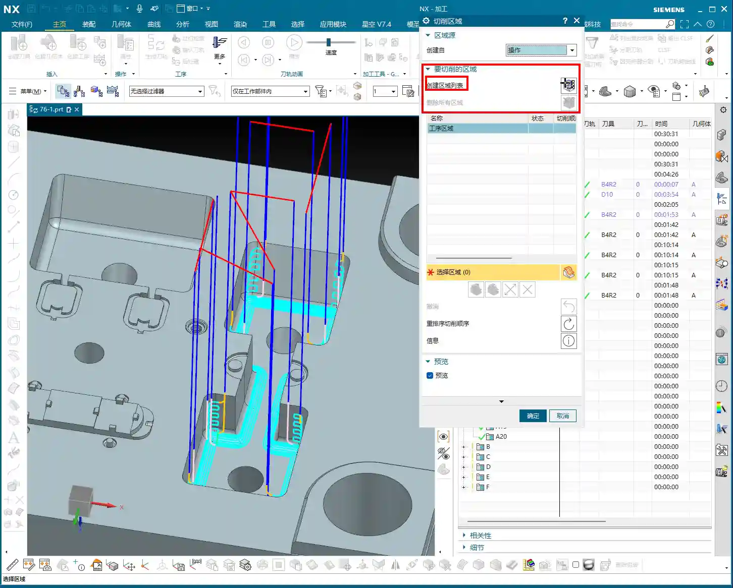
After you first generate a toolpath, the software may automatically analyze and identify numerous areas requiring Corner Cleanup, indicated by small yellow arrows or highlighted regions. But to manage these regions precisely, you need to click on “Create Region List”. This step is crucial; it will clearly list all areas needing Corner Cleanup and automatically perform an initial segmentation based on their geometric features. In our example this time, it automatically divided into 9 smaller regions. With this list, you can perform targeted operations.
This process might take a moment, especially with complex parts. Don’t rush; let the software calculate. It’s like helping you “put an elephant in the fridge”; every step is for subsequent precise control.
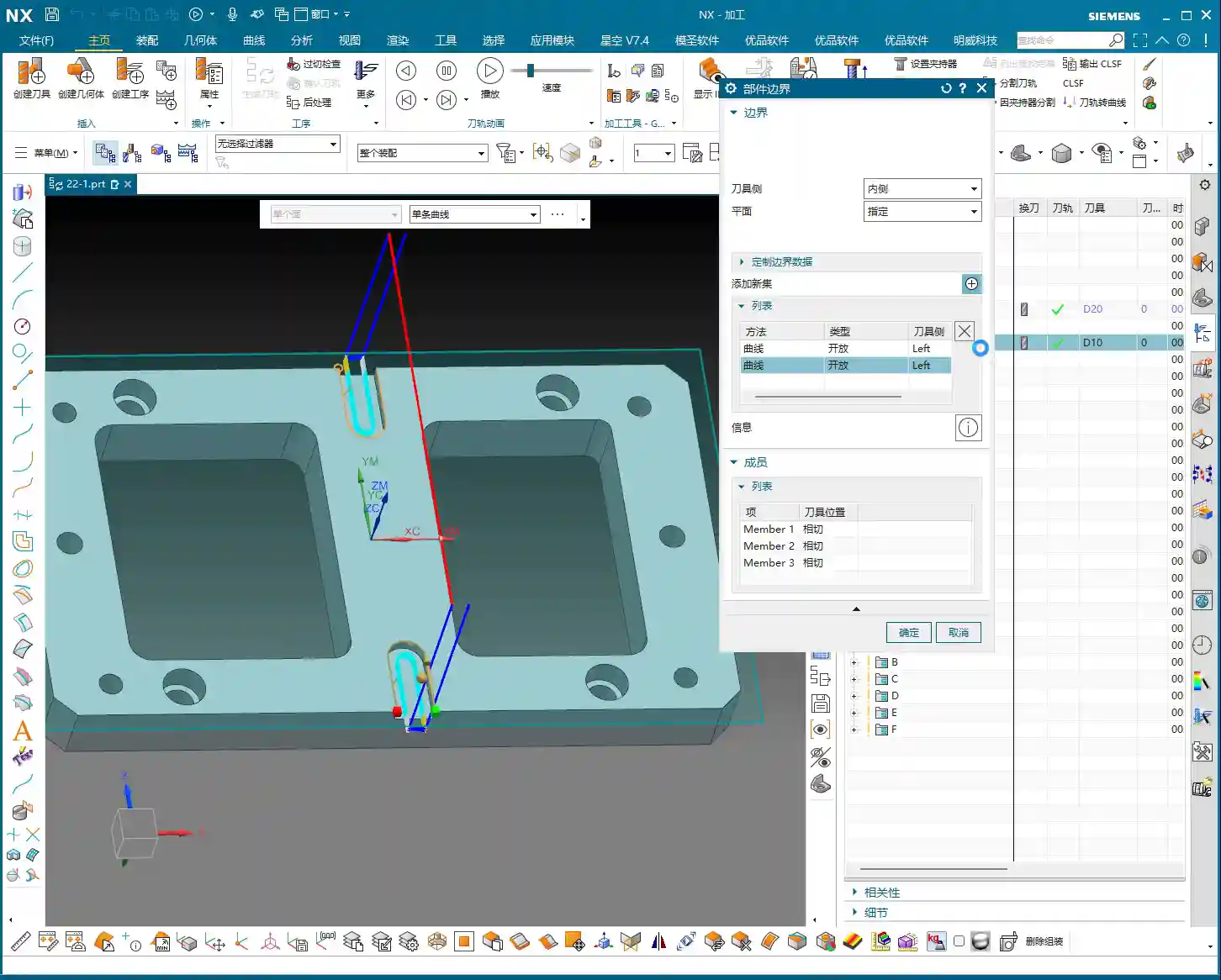
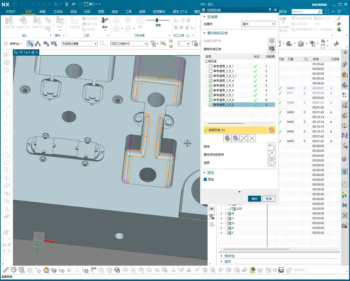
Region Visibility: The Art of Checking and Unchecking
After creating the region list, you’ll see a series of checkboxes. By default, all regions are checked, meaning the software will generate toolpaths for all of them. However, often we only need to machine specific regions or want to temporarily ignore one. In such cases, unchecking (or unselecting) becomes your most frequently used function.
For instance, if I only want to clean up the bottom flat face or a specific corner. I can uncheck all other irrelevant regions. When you regenerate the toolpath, the software will only create toolpaths for the checked regions, treating the unchecked ones as if they don’t exist. This is the most direct and effective method for localized machining control. Imagine if a part has a dozen Corner Cleanup Regions; by machining only one at a time using this check-box function, think of how much time you’ll save!

Split, Merge, and Delete: The Lifecycle of Regions
Deleting Regions: The Irreversible “Hard Stop”
In the Corner Cleanup Region list, if you select a region and click the “Delete” button, that region will be permanently removed. It’s not like unchecking, which only temporarily hides it; it’s genuinely gone. So, make sure you look carefully before operating; don’t accidentally delete a critical region with a twitch of the hand.
Master Wang’s Tip: Don’t expect to recover a deleted region directly like an undo action. If you accidentally delete the wrong one, the only “recovery method” is to first click “Delete All Regions” and then click “Create Region List” again. This way, the software will re-identify and generate all Corner Cleanup Regions, returning to the initial default state. It’s like a “one-click reset” for your Corner Cleanup Regions. So, don’t delete haphazardly; if you must delete, clear them all and rebuild, otherwise, it’s easy to get confused.
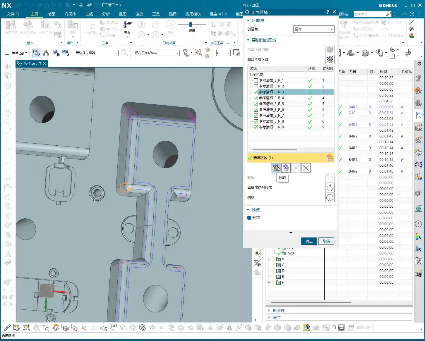
Splitting Regions: Precision Operations for Breaking Down into Smaller Parts
Sometimes, a Corner Cleanup Region automatically identified by the software might be very large or have a complex shape, making it difficult to process with a single toolpath strategy within that region. Or perhaps you want a tool retract movement during machining of this region, rather than a continuous pass. This is when the “Split” function comes in handy.
Select the region you want to split and click “Split”. You can choose to divide it by “Two Points defining a Line” or by “Plane”. Typically, “Plane” is more commonly used; you can drag a plane to define the split line. For example, if we split a region into two halves, the toolpath will change from one large region to two independent smaller regions. The benefit of this is that you can apply different machining parameters to these two smaller regions, or enforce a tool retract between them to avoid potential Chatter risks. For instance, in some deep slots, a mid-pass tool retract for chip evacuation can be very beneficial. But don’t forget, a tool retract is also an air cut and a time cost, so splitting should be done judiciously!

Merging Regions: An Optimization Method for Consolidating Smaller Parts
Where there is splitting, there is merging. If you feel that two previously split regions, or two adjacent regions automatically generated by the software, don’t require a tool retract between them and can be machined in one continuous pass. Or if you find that there are too many tool retracts after splitting, affecting efficiency, then you can “Merge” them back together.
Merging is simple: First select at least two regions you want to merge (e.g., the two parts you just split), then click “Merge”. The software will then treat them as a single entity again. After merging, the toolpath will be more continuous, reducing unnecessary tool retracts and thus improving machining efficiency. It’s like pouring water from two small buckets back into one large bucket, eliminating an extra transfer step.
Reverse and Reorder: Fine-tuning Toolpath Details
Reverse: Changing Cutting Direction
The “Reverse” function is only meaningful for unidirectional machining toolpaths (e.g., one-way milling). Its purpose is to reverse your toolpath’s cutting direction; for example, if it was climb milling, clicking it will switch to conventional milling. But you need to note that in our current zig-zag machining, the tool already moves back and forth, encompassing both climb and conventional milling, so clicking “Reverse” will have no effect whatsoever. Don’t waste your effort here. To use it effectively, you first need to understand whether your current toolpath strategy is unidirectional or zig-zag.

Reorder: Adjusting Machining Sequence
“Reorder”, as the name suggests, adjusts the machining sequence of these Corner Cleanup Regions. When you have multiple Corner Cleanup Regions, their machining order affects the tool’s travel path. Sometimes, the software’s default order might not be optimal, leading to frequent tool retracts and air cuts. By manually or automatically reordering, you can guide the tool along a more logical path, reducing air cut time and thus improving overall efficiency.
Summary: Pitfall Avoidance Guide
- Core Principle: The essence of Corner Cleanup Regions is precise control, not splitting for the sake of splitting, or merging for the sake of merging. Everything should aim for actual cutting performance and machining efficiency. Your final product must be high-quality, scrap rates low, and costs reduced.
- Accidental Deletion: Remember the “delete all and recreate” recovery method, but try to avoid accidental deletion; verify before operating. This isn’t a game; one wrong step could ruin the workpiece or even cause a tool crash.
- Excessive Retracts: Splitting regions will increase tool retracts in the toolpath. If there are too many unnecessary retracts, consider merging them back. Time is money, and air cuts are burning cash.
- Misuse of Reverse: Always remember the distinction between unidirectional and zig-zag machining; don’t fuss with “Reverse” on zig-zag toolpaths. Random clicking without understanding the principle is asking for trouble.
- On-Machine Verification: No matter how good the software simulation looks, the final judgment comes from the machine. During machining, observe the cutting sparks, listen to the cutting sound, and feel the workpiece temperature—these are the real skills you won’t learn from textbooks!
- SEO Tip: When sharing this kind of technical content, keywords should cover “NX Corner Cleanup Region”, “Toolpath Optimization”, “Machining Programming”, “CNC Tips”, combined with pain points like “improve efficiency” and “reduce scrap” to help more aspiring newcomers find us. As engineers, we also need to understand a bit about promotion to spread genuine expertise!
👤 About the Author:
The author is a veteran CNC machining professional with 15 years of industry experience, specializing in UG NX programming. This article is an original work representing personal practical insights.
⚠️ Copyright Notice: Unauthorized reproduction or distribution without prior communication is strictly prohibited.