📝 Key Takeaways:
Reinforcing Rib Programming: From Part to Program
Alright, listen up, everyone! Today, Master Wang will walk you t…
[VIDEO_HERE]
Alright, listen up, everyone! Today, Master Wang will walk you through a common machining case for reinforcing ribs on a component. This might look straightforward, but there’s a lot more to it, especially when it comes to toolpath optimization and preventing heavy tool engagement – that’s the real-world know-how you won’t find in textbooks. We’ll start from scratch and machine both the back and front sides, step by step.
I. Workpiece and Coordinate System Setup: Poor Foundation, Everything Crumbles!
First, once you get the part drawing, you need to understand it thoroughly. These reinforcing ribs aren’t complex in shape, but you need to pay attention to their structural characteristics during machining. Here, it’s fine to machine a little more, but the critical thing is not to damage other areas.
1.1 Workpiece Placement and Fixturing
The first and most crucial step is workpiece placement and fixturing. No matter how advanced your machine tool is, if the fixturing isn’t solid, everything else is useless. Typically, for these reinforcing ribs, we’ll place them on a robust fixture to ensure stability during the machining process. I usually just put it directly on the fixture, simple and straightforward.
1.2 Creating Machining Geometry and WCS
In Siemens NX, we enter the manufacturing module and first create the machining geometry and the WCS (Work Coordinate System).
- Select the “A” coordinate system as the main coordinate. No need to elaborate, it’s the same every time.
- You should be familiar with the tools preset in the tool library, for example, a Ø16 flat end mill, a Ø12 flat end mill, or corner radius end mills. We’ll select others later based on actual requirements.

II. Roughing the Back Side of Reinforcing Ribs: Tool Deflection is No Laughing Matter!
Let’s start with the back side. For these reinforcing ribs, the back side is typically the first operation; we need to rough out its general shape first.
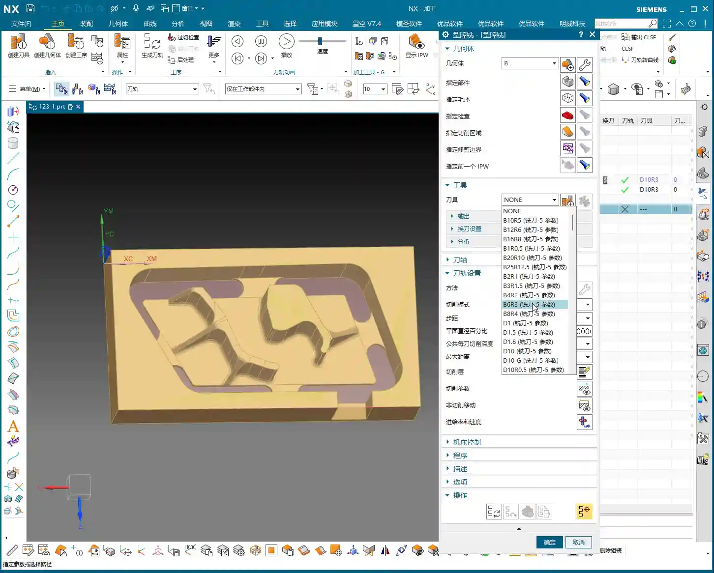
2.1 Tool Selection and Machining Area
Right-click to insert an operation, select “Cavity Mill”. This surface is clearly best suited for Cavity Milling.
- Part Geometry: Directly select the main body of our reinforcing rib.
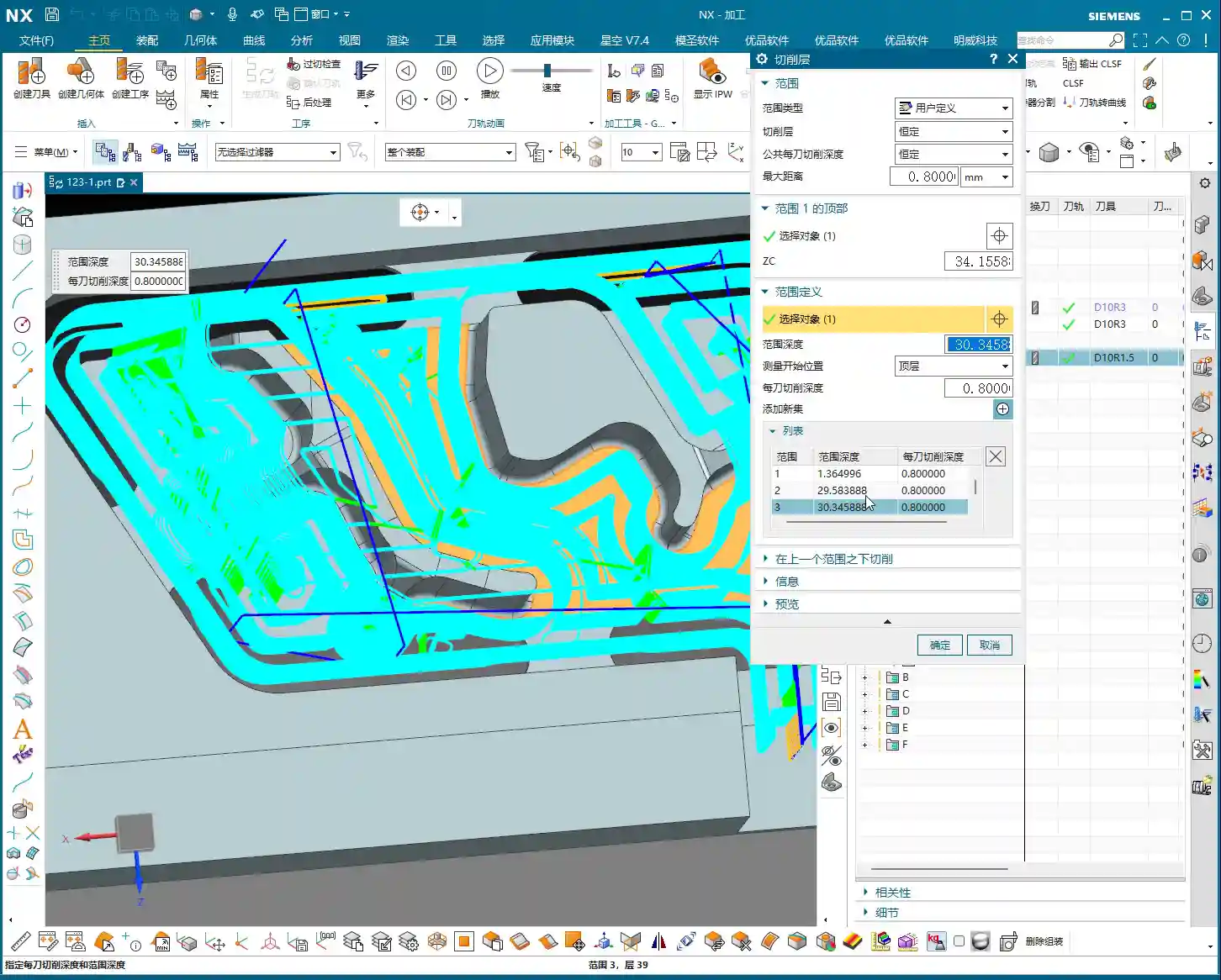
- Tool Selection: First, analyze its corner radius (R-angle). Upon measurement, we find it’s approximately R3. Alright, then directly choose an R3 ball end mill or a corner radius end mill. This way, most of the material can be removed in one go without overcutting.
- Depth of Cut (DOC): It’s approximately 1.4mm. We’ll take a 0.2mm stepdown per pass, taking several passes.
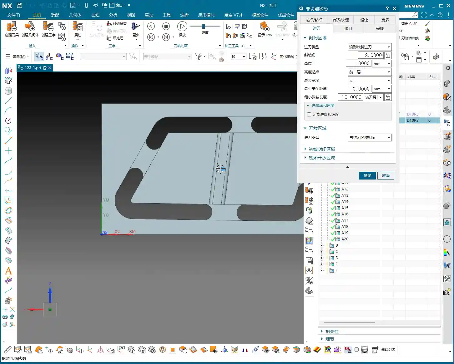
2.2 Toolpath Optimization: No Plunge Cuts!
Generating the toolpath, woah! The tool plunges directly in – that’s unacceptable! Plunge cutting is a major taboo in machining; it can lead to tool breakage, scrap the workpiece, or even damage the machine. Listen up, you must never allow the tool to plunge directly!
- Entry Method Adjustment: In the cutting parameters, change the entry method from the default ‘Direct Plunge’ to ‘Helix or Ramp entry along boundary‘. This way, the tool spirals down like a drill, ensuring even cutting forces, which is better for both the tool and the workpiece.
Master Wang’s Tip: Don’t just rely on software simulation; observe the cutting sparks and listen to the cutting sound. When spiraling down, the sparks will be uniform, and the sound will be stable – that’s the sign of a good toolpath!
- Stock Allowance Setting: For roughing, leaving some stock allowance is essential. Leave a 0.15mm allowance; we’ll finish it later during the finishing pass.

2.3 Avoiding Side Load/Chatter: Safety Distance is Key!
When the program runs, you might notice the tool still ‘stumbling’ in some areas, especially when cutting slopes. This indicates insufficient safety distance.
- Minimum Safe Distance: This parameter might not have been mentioned much before, but it’s extremely practical. Set it to 0.2mm or even 0.3mm. You’ll notice that the tool will approach the machining area from outside with a safe distance before smoothly entering the cut. This avoids the risk of sudden heavy engagement or tool deflection on slopes.
- Cutting Angle Adjustment: For this slope angle, we can adjust it slightly, for instance, from the default 8 degrees to 5 degrees. This makes the tool’s plunge into the material gentler, leading to more stable machining.
III. Roughing the Front Side of Reinforcing Ribs: The Clever Use of Auxiliary Geometry
With the back side done, now let’s tackle the front side. The situation on the front is similar, but we can try some different strategies.
3.1 Copying Operations and WCS Switching
To save time, simply copy the roughing program for the back side. Then modify the WCS, rotate it 180 degrees, and switch to our B coordinate system (offset set to 100, which is for distinction).

3.2 Stock Definition and Auxiliary Geometry Selection: Trade-offs with the Workpiece Feature
In the past, we often used the Workpiece feature (for stock definition). However, for complex parts with reinforcing ribs, using Workpiece sometimes requires creating many auxiliary bodies just to define the stock, which can be quite cumbersome. Therefore, when dealing with these types of parts, I personally prefer to directly select the geometry to define the machining area, which is more efficient.
- Stock Definition: Let’s redefine the stock, setting it to 0 (relative to the part). Then select the part body and its external contours. Also, initially set a stock allowance of 0.01mm.
- Tool Selection: Let’s go back to our previous R3 corner radius end mill. With a 0.8mm Depth of Cut (DOC) per pass.
3.3 Further Toolpath Optimization: Extending Faces and Forcing Entry Direction
After generating the toolpath, we still find some areas where the tool enters from the inside, or the cutting shape isn’t ideal. At this point, we need to employ some ‘advanced techniques’.
- Extend Face: In Siemens NX modeling, slightly extend the boundary faces of the machining area. Note, ‘slightly’ extended, don’t overdo it. The purpose of this is to provide the tool with more generous entry space, preventing it from ‘struggling’ at the actual part boundary.
Master Wang’s Insight: This technique is particularly effective when dealing with concave areas or regions with interference, as it can effectively prevent tool collisions or surface damage.
- Force Approach Direction: In the cutting parameters, change the approach direction from ‘Automatic’ to ‘Inward‘. This way, the tool will always enter from the outside and cut inward, preventing internal plunges.
3.4 Tool Size and Clearance: Smaller Tools Get the Job Done Better!
If the tool still can’t enter certain areas smoothly, it means your tool is too large!
- Tool Replacement: The clearance in these reinforcing ribs is small; our initially selected Ø16 flat end mill or R3 corner radius end mill might not fit. I tried, R12 didn’t work, R10 didn’t work either. Ultimately, we need to switch to a smaller tool like an R1.5 corner radius end mill to smoothly enter these narrow areas for cutting.
- Cutting Trim: To precisely control the machining range, we’ll use the “Trim” function. Select the bottom boundary to ensure the tool only cuts to our desired position, preventing overcutting.
See, now that the toolpath is generated, all tools can enter from the outside and machine perfectly to the bottom. This is the result we’re looking for!
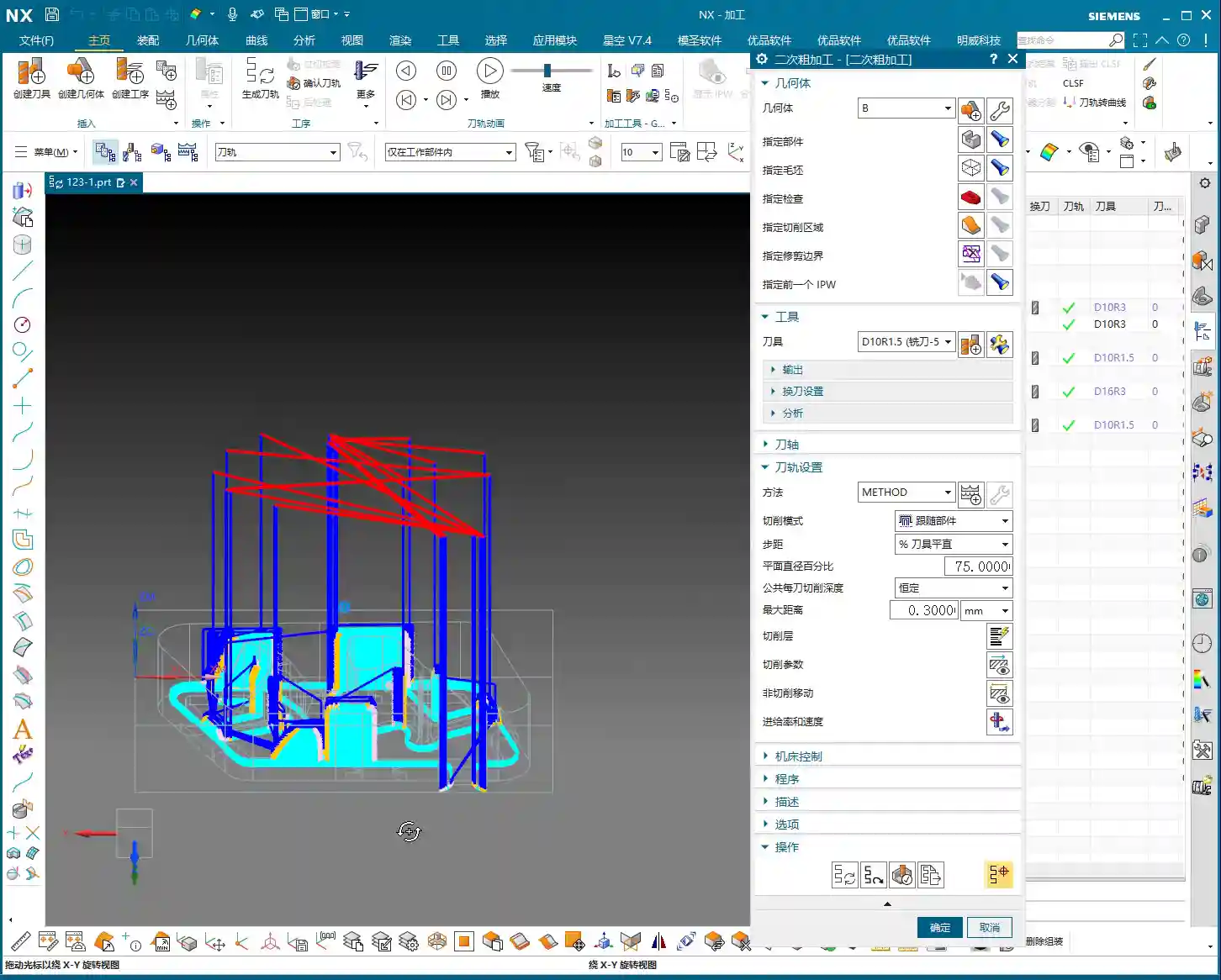
IV. Semi-Finishing: Details Determine Success

Roughing is just the first step; we also need to perform semi-finishing to lay a solid foundation for the final finishing pass.
4.1 Semi-Finishing Strategy
Similarly, we can copy the roughing program and then modify the parameters. This time, our goal is to further reduce the remaining stock left by roughing.
- Tool Selection: Since roughing has already removed most of the material, there’s less stock remaining, so we can’t use a large tool. Let’s still choose an R1.5 corner radius end mill, or an R1 ball end mill, depending on the specific situation. Smaller tools are better for corner cleanup.
- Cutting Parameters: Adjust cutting speed and feed rate appropriately based on material properties. Semi-finishing typically uses slower feed rates and smaller depths of cut than roughing, ensuring better surface quality.
Thus, a complete roughing and semi-finishing program for the reinforcing ribs is complete. All toolpaths effectively mitigate the risks of plunging and heavy tool engagement/chatter, ensuring machining stability and efficiency.
Summary: Pitfall Avoidance Guide
- Entry Method is Key: Absolutely no direct plunge cuts! Helical or ramped entry is the way to go; it significantly extends tool life and protects the workpiece.
- Remember Safety Distance: Set a reasonable minimum safe distance, especially when machining slopes or complex surfaces, to effectively prevent the tool from contacting the workpiece in unintended areas.
- Match Tool Size: When facing narrow machining areas or reinforcing rib clearances, don’t force a large tool. Choose an appropriately sized small tool to ensure smooth tool entry and prevent interference.
- Clever Use of Auxiliary Geometry: For complex reinforcing ribs, appropriately extending machining faces can provide a better entry path for the tool, improving toolpath quality.
- Control Cutting Direction: Forcibly setting an “Inward” approach ensures the tool always enters the machining area from the outside, preventing internal plunges and unstable cutting.
- Practical Experience is Invaluable: Don’t just rely on software simulation; consider the actual machine conditions. During machining, observe the cutting sparks, listen to the cutting sound, and check chip evacuation – these are vital real-world indicators for judging toolpath quality!
👤 About the Author:
The author is a veteran CNC machining professional with 15 years of industry experience, specializing in UG NX programming. This article is an original work representing personal practical insights.
⚠️ Copyright Notice: Unauthorized reproduction or distribution without prior communication is strictly prohibited.