📝 Key Takeaways:
Practical Siemens NX Roughing Optimization for Side Milling Heads
Listen up, fellas! It’s Old Wang, Master Wang here. Today, we’re diving…
[VIDEO_HERE]
Listen up, fellas! It’s Old Wang, Master Wang here. Today, we’re diving back into some “unwritten rules” of Siemens NX programming – the hardcore, practical stuff you won’t find in textbooks. Where did we leave off last time? Ah, right, programming side milling head components. This stuff, it’s not overly complex, but it’s not exactly simple either, especially when dealing with those tricky corners and tight spots. One slip-up, and you’ll run into trouble. Today, we’re going to start with program duplication and systematically uncover and resolve all those potential pitfalls for you!
I. Program Duplication and Roughing Area Selection: Saves Effort, Not Vigilance
Picking up where we left off, when roughing these side milling heads, we’re all about efficiency. If you have an existing program template, just copy it. It saves you from starting from scratch – that’s experience talking. But saving effort doesn’t mean you can let your guard down!
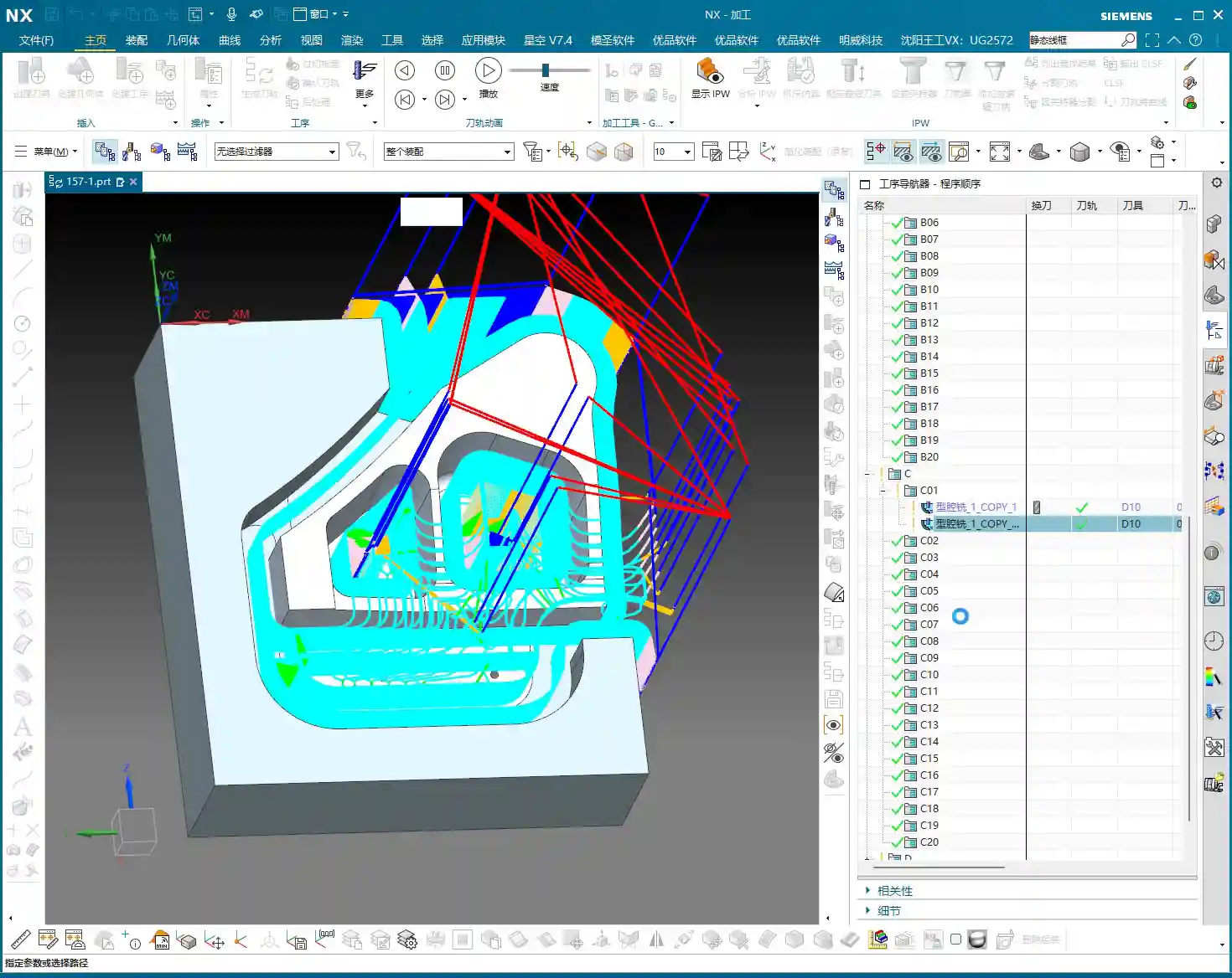
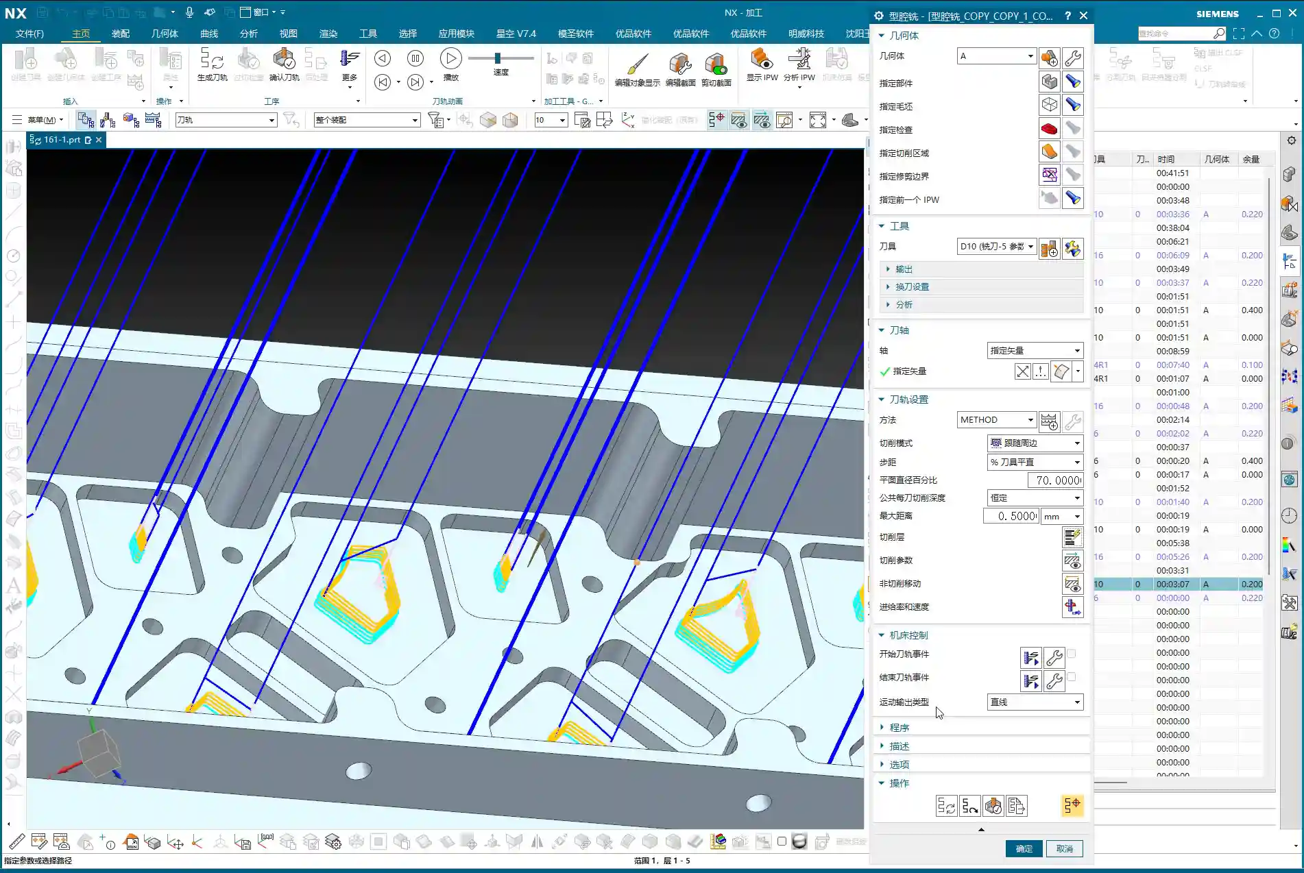
1. Initial Roughing Range Selection
For the areas we need to **roughing**, just copy the previous program, double-click to open it, and start modifying. This operation, practice makes perfect.
2. Defining the Blank and Cutting Faces
The **Blank** – you absolutely *must* define this first! Otherwise, you’ll have no idea where the tool is cutting, or where it’s supposed to cut. Then, select the first face you want to rough. Pay attention here: sometimes, when you directly click on the **Workpiece/Part Stock**, it might not select. Don’t panic. Just click on the face itself, or select the boundary line above it. Siemens NX will automatically help you define the depth.
Master Wang’s Insight: Siemens NX can be a bit quirky sometimes. If you can’t click it, try clicking from a different angle or selecting a different geometric element. The goal is always the same: ensure the system clearly understands your machining range. Don’t get stuck on one point; be flexible!

II. Programming Taboo: Random Clicks Ruin Everything
Lads, remember this point; it’s a lesson learned the hard way!
1. Once Programmed, Do Not Touch
You’ve painstakingly programmed it, the toolpaths are calculated, and you’re just waiting to generate the G-code for the machine. At this point, control your hands! Absolutely do not click around other parts of the Siemens NX interface before the program is generated or saved!
2. The Painful Lesson of Lost ‘Part Stock’
I’ve seen it happen: you’re programming, accidentally click another area, and when you come back, boom! Your previously selected **Workpiece/Part Stock** is gone! Or it’s been changed to a different face. At that point, your toolpath could be completely wrong. At best, it undercuts; at worst, it causes an **overcut**, rendering your workpiece scrap!
Master Wang’s Warning: After programming, generate the toolpath first, check it thoroughly, then save. It’s like drawing blueprints and sending them to production without approval – if something goes wrong, who’s responsible?

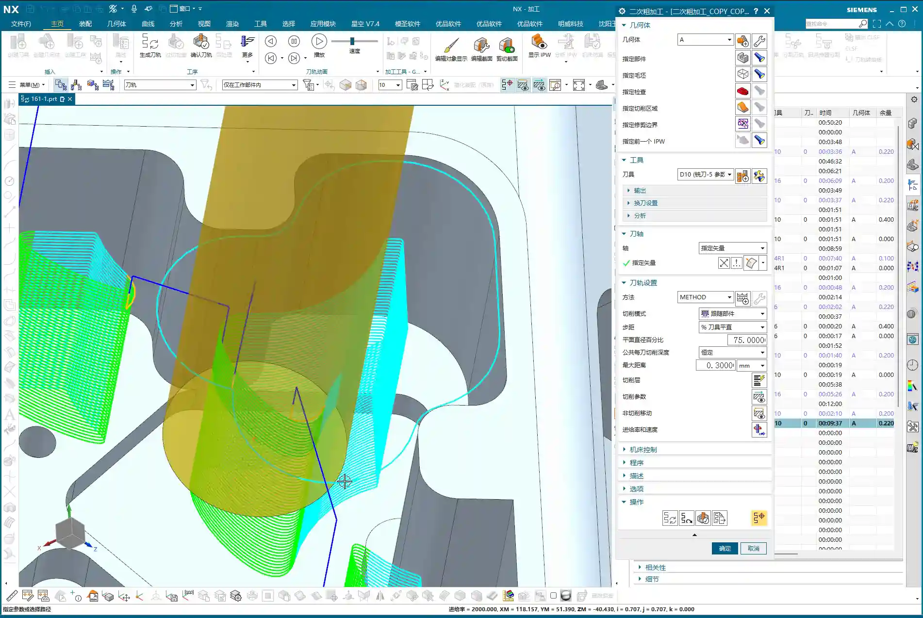
III. Secondary Roughing (Re-roughing): Cleaning Up Dead Zones, Leaving No Remnants
The first roughing pass often just removes the bulk of the material with a larger tool. But there are always small features, deep cavities, and sharp corners on the workpiece that a large tool can’t reach. That’s when **Re-roughing** becomes especially critical.
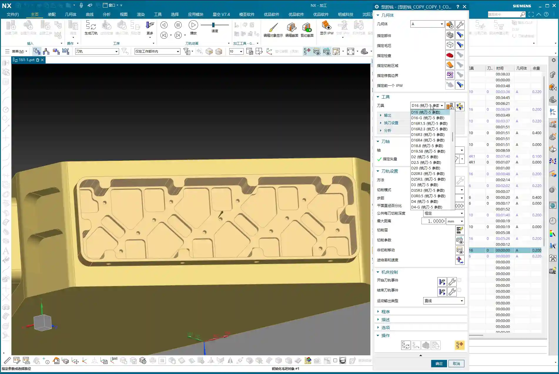
1. Remnant Material Detection and Tool Selection
Upon careful analysis, you’ll find that for complex structures and internal cavities like those in a side milling head, many corners and grooves still have significant remnant material. At this point, you’ll need to switch to a smaller tool for cleanup. If you used a D10 (10mm diameter) tool for the first pass, for re-roughing, consider a D8 (8mm diameter) or even a D6 (6mm diameter). Of course, the specific tool selection depends on your remaining stock and the workpiece geometry. In my experience, sometimes a D8 works better than both a D10 and D6 – it’s a good compromise.
2. Controlling Remnant Material and Depth of Cut
During re-roughing, the **stock** will definitely be smaller than the initial roughing. For instance, if you left 0.8-1mm (approx. 0.03-0.04 inch) the first time, for re-roughing, you might leave 0.2-0.5mm (approx. 0.008-0.02 inch). The **depth of cut** also needs precise control; sometimes, you only need to clean up a specific face. You need to clarify your objective, select the specific **Bottom Face** you intend to re-rough, and ensure the tool only works in that designated area.

IV. Fine-Tuning Siemens NX Parameters: The Secret to Resolving Undercuts and Overcuts
Siemens NX is a great software, but it still needs to follow your commands. Some parameters, if not set correctly, can easily lead to problems.
1. Minimum Cut Length: Small Parameter, Big Impact
Have you ever encountered a situation where there’s clearly material remaining, but the tool just doesn’t cut it? Or the cutting path is discontinuous? It’s highly likely that the Minimum Cut Length parameter is to blame. As mentioned in the audio, the default 45% might be too large, causing many small areas to be completely ignored. We need to change it to 10% or even smaller; only then can those corner and cavity remnants be cleaned up.
Master Wang’s Tip: This parameter prevents the generation of excessively short, meaningless toolpaths, but too much of a good thing can be bad. Adjust it flexibly based on the dimensions of the workpiece features; don’t let the tool ‘miss’ those small remnants.
2. Boundary Selection: Small Errors Lead to Major Overcuts
Sometimes, you change a parameter, and the toolpath shifts, even resulting in an overcut. This is likely because your previously selected boundaries or hierarchical relationships were re-evaluated by the system after the parameter adjustment, leading to errors. When this happens, don’t be afraid of the hassle. Re-select the boundaries and levels of the cutting area, and clearly re-specify the top and bottom faces. This will be much faster than spending ages trying to figure it out!

V. Retraction Optimization Secrets: Applying Automatic and Relative Planes
**Retraction** refers to the path the tool takes when lifting from one cutting area to another. Lifting too high wastes time, while lifting too low risks tool collisions or marking the workpiece. This is a critical factor directly impacting machining efficiency and safety!
1. Avoiding Excessive ‘Automatic Plane’ Retraction Heights
Have you noticed that sometimes Siemens NX generates ridiculously high retractions? As mentioned in the audio, the default value for the Automatic Plane is set to 100 – this definitely won’t do! How much time is wasted if the tool lifts up to 100mm (approx. 3.9 inches) every time before cutting down again?
2. Relative to Plane and Precise Control
To resolve the issue of excessive retraction heights, you can try the following methods:
- Reduce the value of the Automatic Plane, for example, to 20mm (approx. 0.8 inches).
- For more advanced control, use the Relative to Plane method. Designate an appropriate reference plane, then set the tool’s lift-off distance relative to this plane, for example, 50mm (approx. 2 inches).
- For certain critical areas, you can even directly **specify a face** as the retraction start/end point, then manually input the lift height, such as 10mm (approx. 0.4 inches). This allows the tool to retract shorter distances, stay closer to the workpiece, and save time.
Master Wang’s Experience: Retraction optimization is one of the core essentials in Siemens NX programming. Don’t underestimate these few millimeters of distance; they accumulate to significantly reduce your machining cycle time and boost economic efficiency.
VI. Conquering Stubborn ‘Overcuts’: Specifying Top/Bottom Faces and the ‘Add Thickness’ Method
The most frustrating issue is those inexplicable overcuts. It looks fine, but as soon as you generate the toolpath, it takes an extra cut, and the workpiece is ruined!
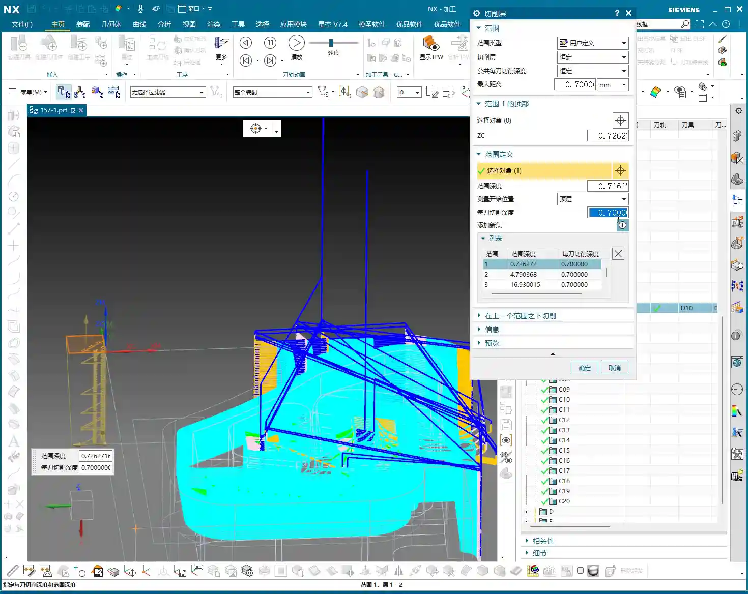
1. Reconfirming Top/Bottom Faces and Cutting Layers
When encountering an overcut, don’t rush; troubleshoot it step by step. First, recheck your defined **Top Face**, **Bottom Face**, and **Cutting Layers**. Was a particular layer selected incorrectly? Or was a certain layer completely useless but mistakenly used by the system? As mentioned in the audio, some layers are redundant; just delete them. Ensure your cutting range is precise and accurate.
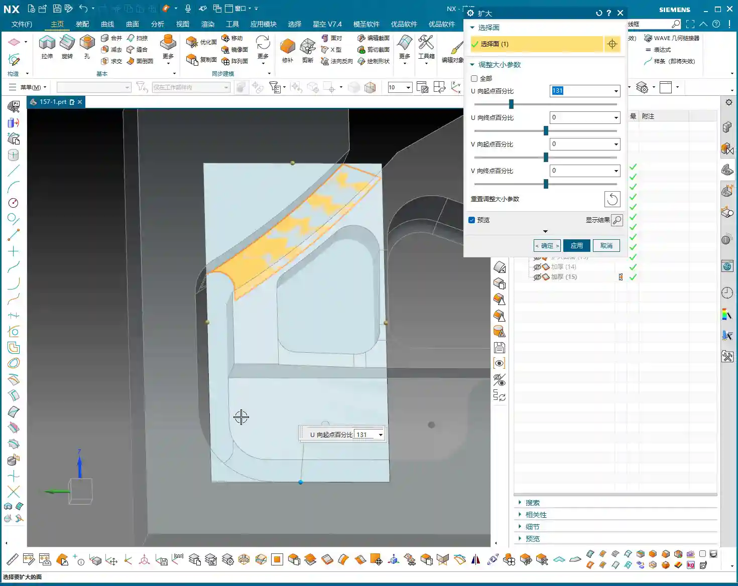
2. Peculiar Overcuts and the Ultimate ‘Add Thickness’ Trick
Sometimes, you’ll encounter some very strange overcut phenomena, especially on small-sized features. The tool clearly shouldn’t go there, yet it takes a cut anyway, and this cut is completely meaningless, a pure waste of time. In such cases, you might not even be able to eliminate it through conventional methods. As also mentioned in the audio, this is truly unimaginable software behavior!
At this point, Old Wang will teach you a killer move – **Add Thickness. This isn’t about adding stock; it’s about assigning an additional thickness in the Z-axis direction to your machining area or feature within Siemens NX. For instance, in the ‘Workpiece/Part Stock’ settings or the cutting parameters, provide a small positive value, like 1mm (approx. 0.04 inch). It’s like giving that area a layer of ‘armor.’ When Siemens NX calculates the toolpath, it will avoid that ‘armor’ layer, thereby preventing overcuts. While this trick might seem a bit ‘brute force,’ it consistently works for certain stubborn overcuts!
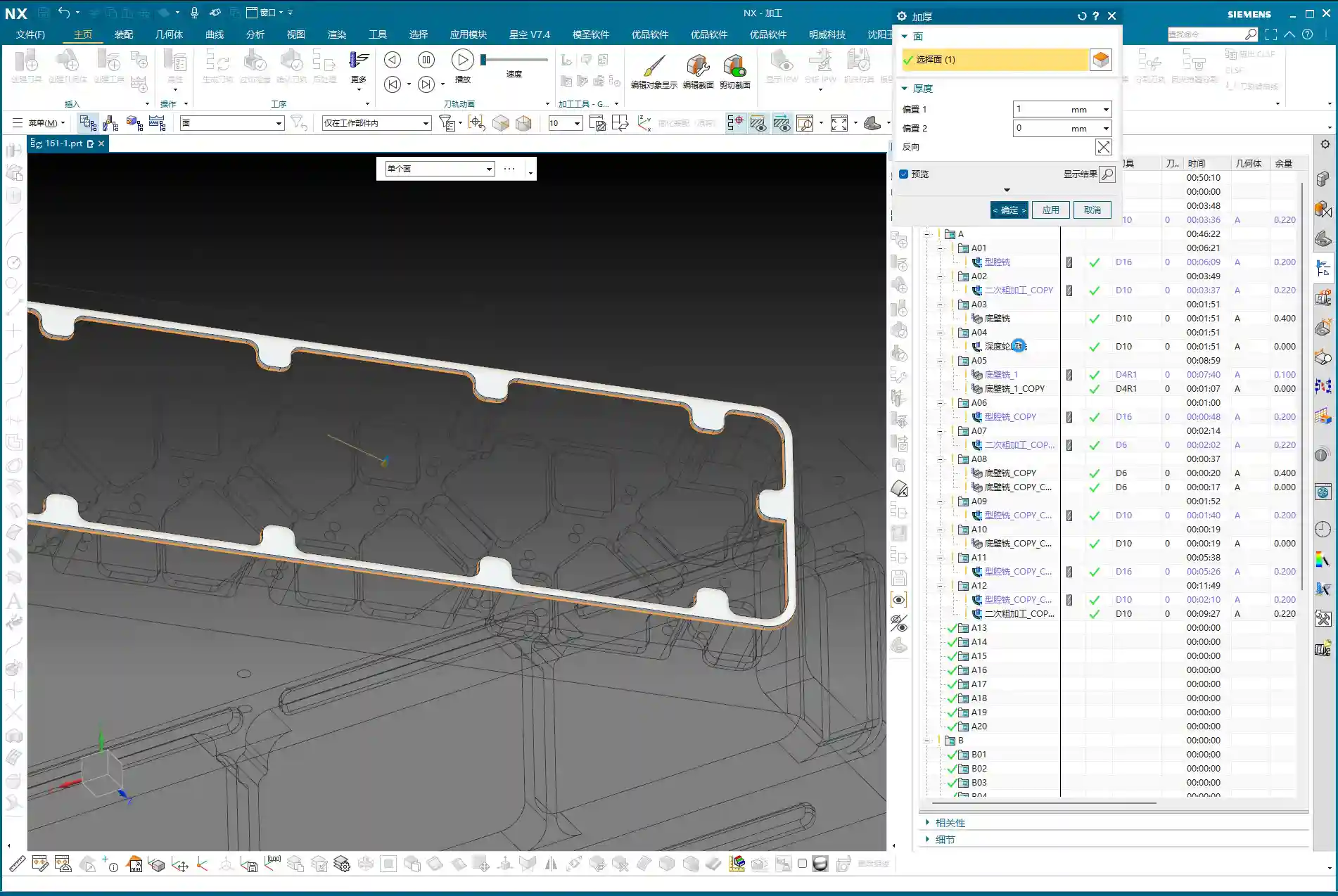
Master Wang’s Advice: This ‘Add Thickness’ isn’t a magic bullet. It’s a temporary solution to potential calculation bugs or illogical toolpaths that Siemens NX might generate under specific geometric conditions. Before using it, make sure to understand its principle and verify it repeatedly in simulation!
Summary: Pitfall Avoidance Guide
Alright, fellas, today we’ve thoroughly covered several major pitfalls commonly encountered in side milling head roughing. Remember the following points to ensure stable machining:
- Do Not Click Randomly After Programming: Especially concerning the selection of blank and boundaries. Once defined, don’t mess with them to prevent ‘Workpiece/Part Stock’ loss or misalignment.
- Make Good Use of Secondary Roughing to Clean Remnant Corners: After a large tool roughs out material, there are always small areas that aren’t clean. Switching to a smaller tool for secondary roughing is standard practice to ensure part accuracy and surface quality.
- Be Flexible with the Minimum Cut Length Parameter: Setting this too large can lead to small areas being undercut; setting it too small might result in excessively fragmented toolpaths. Determine it based on the workpiece feature dimensions.
- ‘Automatic Plane’ Retraction Too High?: Change to Relative to Plane or manually set the retraction height. The goal is to reduce air cutting time and improve efficiency, but also ensure a safe clearance distance.
- Conquering Stubborn Overcuts: First, carefully check the top/bottom faces, cutting layers, and boundary definitions. If it still persists, for those peculiar, meaningless overcuts, try to **add thickness in the Z-axis direction** to the feature. This is often an effective solution for such ‘software logic issues’.
- Don’t Just Rely on Simulation, Watch the Cutting Sparks: No matter how realistic software simulation is, it can’t compare to the sparks, sounds, and vibrations during actual machining on the machine. Observe more, think more – that’s real skill.
Alright, that’s it for today’s lesson. Go back, ponder on it, and next time, we’ll discuss other topics!
👤 About the Author:
The author is a veteran CNC machining professional with 15 years of industry experience, specializing in UG NX programming. This article is an original work representing personal practical insights.
⚠️ Copyright Notice: Unauthorized reproduction or distribution without prior communication is strictly prohibited.