📝 Key Takeaways: Master Wang explains the Siemens NX Hole Milling operation and feature geometry. The tutorial emphasizes a 2D machining perspective, detailing common operations like Hole Milling and Drilling. It highlights WCS coordinate system establishment, hole dimension verification, and deeply analyzes the “Specify Feature Geometry” function. Master Wang teaches how to flexibly adjust parameters like diameter and depth from automatic to “User Defined,” and combines this with practical machine operation experience, emphasizing the importance of avoiding overcutting and recognizing cutting sparks. A practical pitfall avoidance guide is included to help you precisely control hole machining in Siemens NX.
Master Wang’s Talk: The Ins and Outs of Hole Machining
Alright apprentices, listen up! Today we’re diving deep into hole machining in Siemens NX. This operation might seem simple, but there’s a lot more to it than meets the eye, especially the practical tricks that textbooks don’t teach. You’ll want to pay close attention. We’ll start with the most common Hole Milling operation and its feature geometry. Remember, for now, we’re sticking to 2D machining. Forget about fancy 3D stuff for a moment; let’s build a solid foundation first!
The Hole Machining Family: Common Operations at a Glance
There are quite a few operations in NX that deal with ‘holes,’ so let me break them down for you. These are the ones we commonly use in the shop, mostly 2D operations. Understand these first, and then we’ll go deeper:
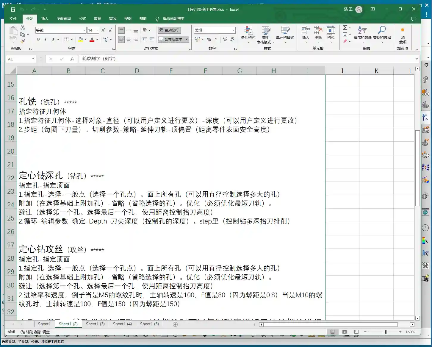
- Hole Milling: This is today’s main topic, primarily used for milling holes. It’s highly efficient, especially suitable for machining larger diameter holes.
- Spot Drilling: Used for creating a center dimple to accurately position the drill for subsequent drilling, ensuring the drill doesn’t wander.
- Drilling: Directly drilling holes with a drill bit. This is the most fundamental hole machining method.
- Tapping: For machining threaded holes. This requires extremely precise coordination between spindle speed and feed rate; one mistake and the part is scrap.
- Centering: Another type of positioning, sometimes used with spot drilling, chosen based on the specific workpiece and precision requirements.
- Boring: Using a boring bar to enlarge and correct hole diameters, improving accuracy and surface quality. This is key for achieving high-precision holes.
- Reaming: Using a reamer to fine-tune hole diameters and surface roughness, further enhancing precision and finish.
- Deep Hole Drilling: A specialized machining strategy for deep holes, requiring consideration of chip evacuation, cooling, and preventing drill runout.
- Helical Milling: Also known as helical interpolation, using an end mill to machine holes with a helical plunge, resulting in stable cutting and good chip evacuation, suitable for hard materials or large holes.
As for things like 3D solid contours, 3D chamfering, or 3-axis deburring, don’t rush into those yet. They’re advanced techniques and not used as frequently. We’ll cover them separately if the opportunity arises. For now, focus on mastering these fundamental, commonly used operations!
Workpiece Preparation: Coordinate System and Hole Dimension Verification
Before you even think about machining, get your workpiece and coordinate system sorted. This is the absolute first step on the shop floor, and it’s no different in NX.

Establishing and Positioning the Coordinate System
In Siemens NX, we first create the Work Coordinate System (WCS). Listen closely, this WCS is as critical as tool offsetting on the machine. It dictates the starting point and direction for all your toolpaths. Typically, we set the WCS origin at the center of the workpiece, or at a reference point that’s easy for tool offsetting. I personally prefer to have the Z-axis pointing upwards, in the direction of our tool feed. It looks right and reduces errors. Don’t underestimate this small habit; it can save your skin when it matters!
Once the WCS is established, you need to verify it. Even though NX offers simulation, us veteran machinists live by ‘seeing is believing!’ It’s like how you always do a dry run after tool offsetting to confirm clearance. Make it a habit to ensure the WCS positioning is logical to prevent unexpected issues during machining.
Hole Dimensions: Eye it, Measure it, Know it Cold
Before machining, you need to be intimately familiar with the holes you’re going to work on. In NX, you can measure the hole diameter and depth. For example, as mentioned, holes might measure Ø32 or Ø20.5. Don’t just rely on the drawing; check the actual model. Are multiple holes symmetrical? Are all dimensions consistent? This is like when you get a new part; you first run a caliper over it to spot any obvious issues. Sometimes there can be ‘hidden traps’ between the design drawing and the actual model.

Core: Hole Milling Operation and Feature Geometry Explained
Alright, preparation is complete. Let’s get hands-on with the “Hole Milling” operation.
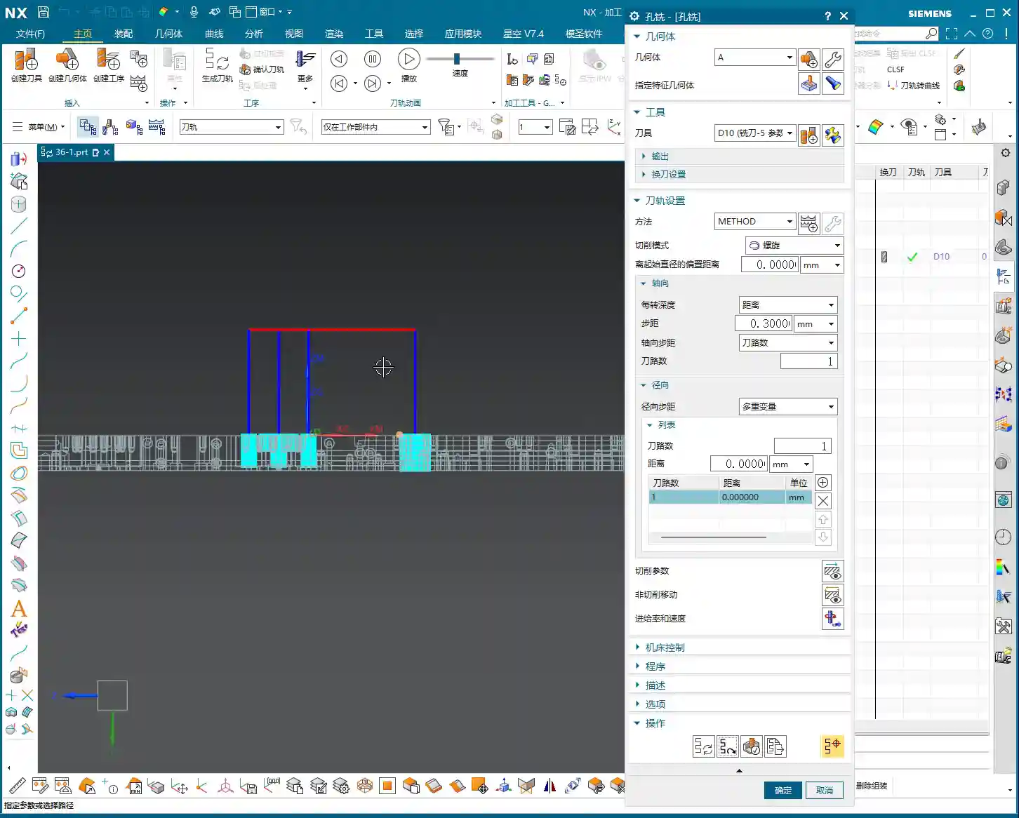
Quick Start: Hole Milling
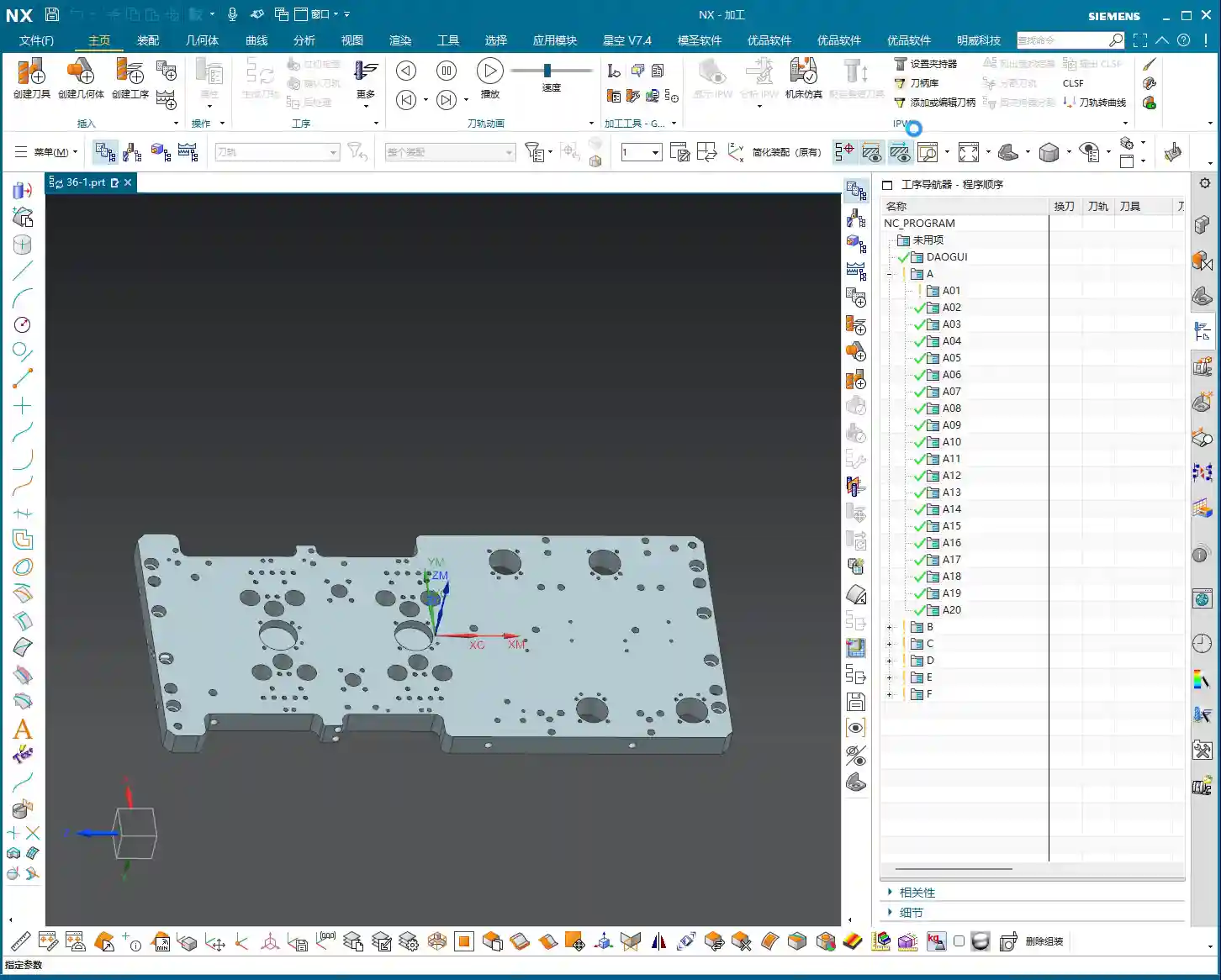
To perform hole milling, simply double-click the “Hole Milling” operation in NX. Then, in the pop-up window, you need to create a geometry feature, such as selecting the default “A” or your custom geometry. This step tells NX which area you intend to machine. The operation itself is very straightforward, unlike some older operations with tedious steps.

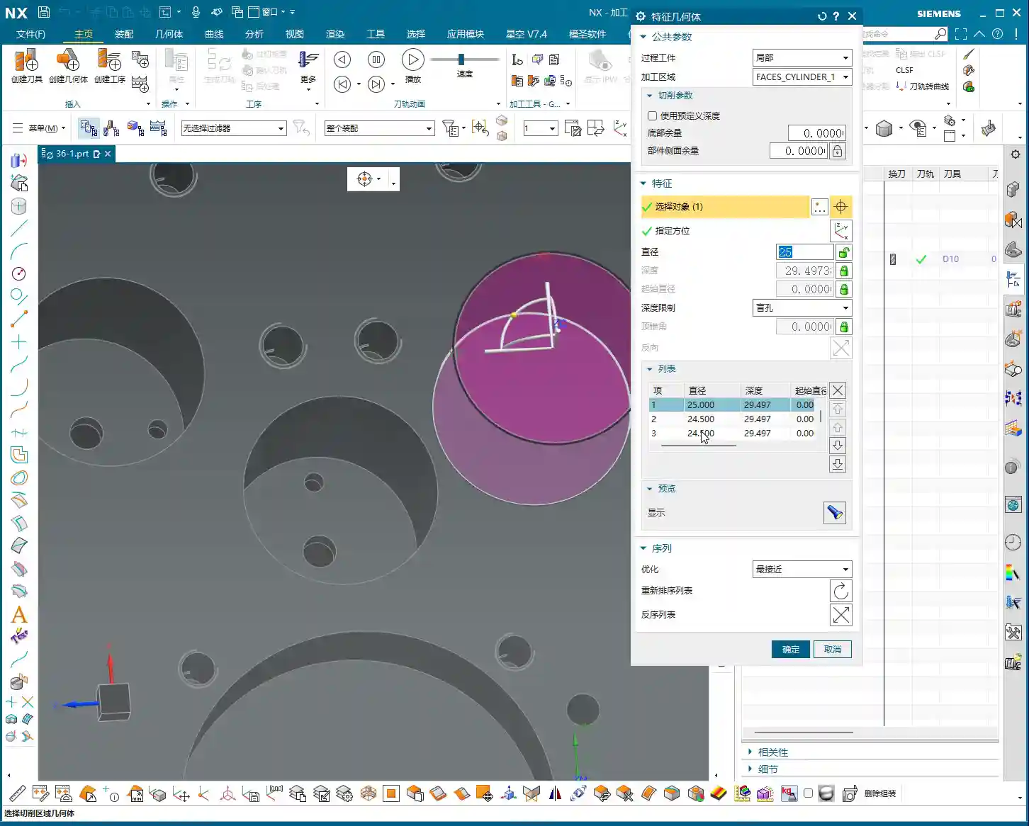
Specifying Feature Geometry: Selecting the Right “Target” is Key
Listen closely, this is critically important! After entering the Hole Milling operation, you’ll see an option called “Specify Feature Geometry.” Click on it, and NX will prompt you to select the holes you want to machine. This is like standing at the machine and clearly telling the machinist, “Drill this hole, bore that one.” Whichever hole you select, NX will machine that hole. You can select them individually or batch-select multiple holes. Once selected, NX will automatically identify the diameter and depth of these holes.
- Stock Settings: For now, we can skip options like “Process Tolerance,” “Trim Stock,” or “No Stock.” Stock allowances can be uniformly adjusted in more advanced parameter settings, so there’s no need to fiddle with them here every time. “No Stock” here simply means we generally don’t apply additional stock settings in this particular dialog.
- Key Information: Once you select the hole, NX will automatically display its diameter (e.g., Ø20.5mm) and depth (e.g., 29.4999mm). These two parameters are the most critical data for hole machining, and you must know them inside out!
After selecting the holes and a suitable tool, simply generate the toolpath, and a basic hole milling program is ready. Isn’t that simpler than you thought? The key is to select the correct geometry, and NX automatically determines most of the parameters for you.
Advanced: Flexible Adjustment of Hole Parameters and Precision Control
While default parameters are convenient, as machinists, we must have the ability to adjust and control them. This is especially true when dealing with non-standard parts, special materials, or when precision issues arise.

Modifying Hole Diameter: From “Automatic” to “User Defined”
You might notice that, by default, NX’s automatically identified hole diameter and depth cannot be directly modified; they appear “grayed out,” preventing input. Listen up, this isn’t NX stopping you from making changes; it simply thinks it has already determined the correct values for you. But if we need to make an adjustment, we have to tell it, “We’re taking control.”
To modify the hole diameter, you must change the corresponding “Parameter Definition Method” or similar option (referred to as “decimal” in the audio, but usually a dropdown menu in actual operation) from “Automatic” to “User Defined.” Once set to “User Defined,” you can freely input your desired diameter.
- Practical Example: For instance, changing a Ø20.5mm hole to Ø25mm. NX won’t throw an error, but when you generate the toolpath, you’ll see obvious “overcutting.” At this point, don’t just rely on software simulation; you need to know that on a real machine, one cut like that, and the part is scrap! This scenario can easily lead to excessive Depth of Cut (DOC) or even scrap the part directly. Don’t assume there’s no problem just because the software doesn’t flag it; that’s deceptive!
- Flexible Adjustment: You can decrease the diameter to Ø20mm or increase it to Ø50mm, and NX will generate the toolpath according to your input. This is particularly useful when dealing with non-standard holes, irregular holes, or when needing to leave stock for finishing passes. However, you must be absolutely clear in your mind whether the modified dimension matches your tool and meets your process requirements.
Adjusting Hole Depth: Precise Control for Deep Hole Machining
Similarly, hole depth can also be flexibly adjusted. For example, you can set the depth of the first hole to 10mm, the second to 20mm, the third to 50mm, or even a deeper 100mm. This is crucial for machining multi-step holes, blind holes, or holes with varying depth requirements. Depending on material properties and tool conditions, we sometimes employ strategies like layered machining or pecking for chip evacuation, and flexible depth control is fundamental to implementing these strategies.
Batch Modification: Efficiency is King
If you have multiple holes of the same size that need adjustment, there’s no need to change them one by one. In the “Specify Feature Geometry” interface, you can hold down the Ctrl key to select multiple holes, or drag-select multiple holes, then change their “Parameter Definition Method” to “User Defined” all at once, and finally input your desired diameter or depth. This is a powerful trick for boosting efficiency. In our machining world, time is money, so save every step you can!
Master Wang’s Practical Secrets: Fine-Tuning Dimensions and Tolerances
Sometimes, when you encounter precision issues at the ±0.005mm (approx. 0.0002 inch) level, software alone won’t cut it. That’s where experience comes in! For example, machining aluminum versus titanium alloys – their thermal expansion coefficients differ, so cutting parameters and stock allowances must be adjusted. If a hole’s diameter is slightly off, you can achieve the correction by modifying tool compensation, or by fine-tuning the diameter of this feature geometry within Siemens NX. But remember, such fine-tuning must be built upon a deep understanding of material characteristics, tool wear, and machine accuracy. Don’t just rely on software simulation; you need to observe the cutting sparks, listen to the cutting sound, and feel the part. Those are the true skills!
Summary: Pitfall Avoidance Guide
- Pitfall 1: Blindly trusting default parameters. NX’s automatically identified parameters are based on the model, but they may not always align with your actual machining requirements. Especially for hole diameter and depth, always verify against the print and process specifications, and modify manually when necessary.
- Pitfall 2: Failing to verify after modifying parameters. After changing diameter or depth, always regenerate the toolpath and perform simulation verification. More importantly, you must be mentally prepared and understand whether this modification will lead to overcutting, tool breakage, or dimensional deviations on a real machine. Just because the software doesn’t throw an error doesn’t mean the machine won’t!
- Pitfall 3: Neglecting precise positioning of the coordinate system and workpiece. The accuracy of all hole machining operations relies on an accurate WCS. If the WCS isn’t correctly set, all subsequent holes will be off, the part will be scrapped, wasting both time and material.
- Pitfall 4: Disregarding material characteristics. Different materials (from common aluminum to titanium alloys, high-temperature nickel-based alloys) have vastly different cutting parameters, tool selections, and heat treatment distortion tendencies. These factors must be fully considered during machining, for instance, for materials sensitive to thermal deformation, layered feeds and cooling methods must be accounted for.
- Pitfall 5: Only focusing on the toolpath and ignoring cutting sparks. No matter how realistic Siemens NX simulation is, it’s still virtual. To truly judge the machining status, you need to rely on your eyes and ears. Spark color, chip formation, and tool sound – these are the machine “speaking.” An experienced machinist can discern issues like excessive Depth of Cut (DOC) or chipping from these details.
- Pitfall 6: Fearing user-defined parameters. Many beginners are afraid to change automatic parameters to user-defined, thinking it leads to errors. But to become a master, you must grasp this ability for flexible adjustment. While ensuring safety, try more, learn from your experiences, and only then can you truly master Siemens NX.
Alright, that’s it for today’s lesson. Go home and digest all of this. Get hands-on and practice; you won’t learn just by listening!
[EXCERPT]
Master Wang explains the Siemens NX Hole Milling operation and feature geometry. The tutorial emphasizes a 2D machining perspective, detailing common operations like Hole Milling and Drilling. It highlights WCS coordinate system establishment, hole dimension verification, and deeply analyzes the “Specify Feature Geometry” function. Master Wang teaches how to flexibly adjust parameters like diameter and depth from automatic to “User Defined,” and combines this with practical machine operation experience, emphasizing the importance of avoiding overcutting and recognizing cutting sparks. A practical pitfall avoidance guide is included to help you precisely control hole machining in Siemens NX.
👤 About the Author:
The author is a veteran CNC machining professional with 15 years of industry experience, specializing in UG NX programming. This article is an original work representing personal practical insights.
⚠️ Copyright Notice: Unauthorized reproduction or distribution without prior communication is strictly prohibited.