📝 Key Takeaways: Apprentices, Master Wang here! Today, we’re going to break down the ‘Space Range Parameters’ in UG NX 1980 that make toolpaths smoother and machining more efficient. From first pass extension to merge distance, and how to avoid collisions, these are practical skills you won’t learn from textbooks. Listen up!
Hello everyone, I’m Master Wang! Today, we’ll pick up where we left off. Last time, we covered all the corner parameters. Logically, I could jump straight to the ‘More’ option above, but we’ll save that for later. Today, let’s focus on a very practical and crucial topic: Space Range Parameters.
Skipping Redundancy: Bottom Face Thickness vs. Blank Thickness
Look at the blank settings above, isn’t there a ‘Thickness’ option? For example, ‘blank thickness’ or ‘bottom face thickness’. Actually, these concepts are quite similar, and their meanings are largely consistent. In Siemens NX 1980, many parameters have these kinds of interconnections. So, today we won’t dwell too much on these redundancies; let’s get straight to more practical matters.
Core Concept: Extend Bottom Face To
Listen up, this ‘Extend Bottom Face To’ is a key player in ‘Space Range’! It determines how far the toolpath can extend when machining the bottom face. We’ll start with the most commonly used ‘First Pass Extension Amount’, and then look at other options.
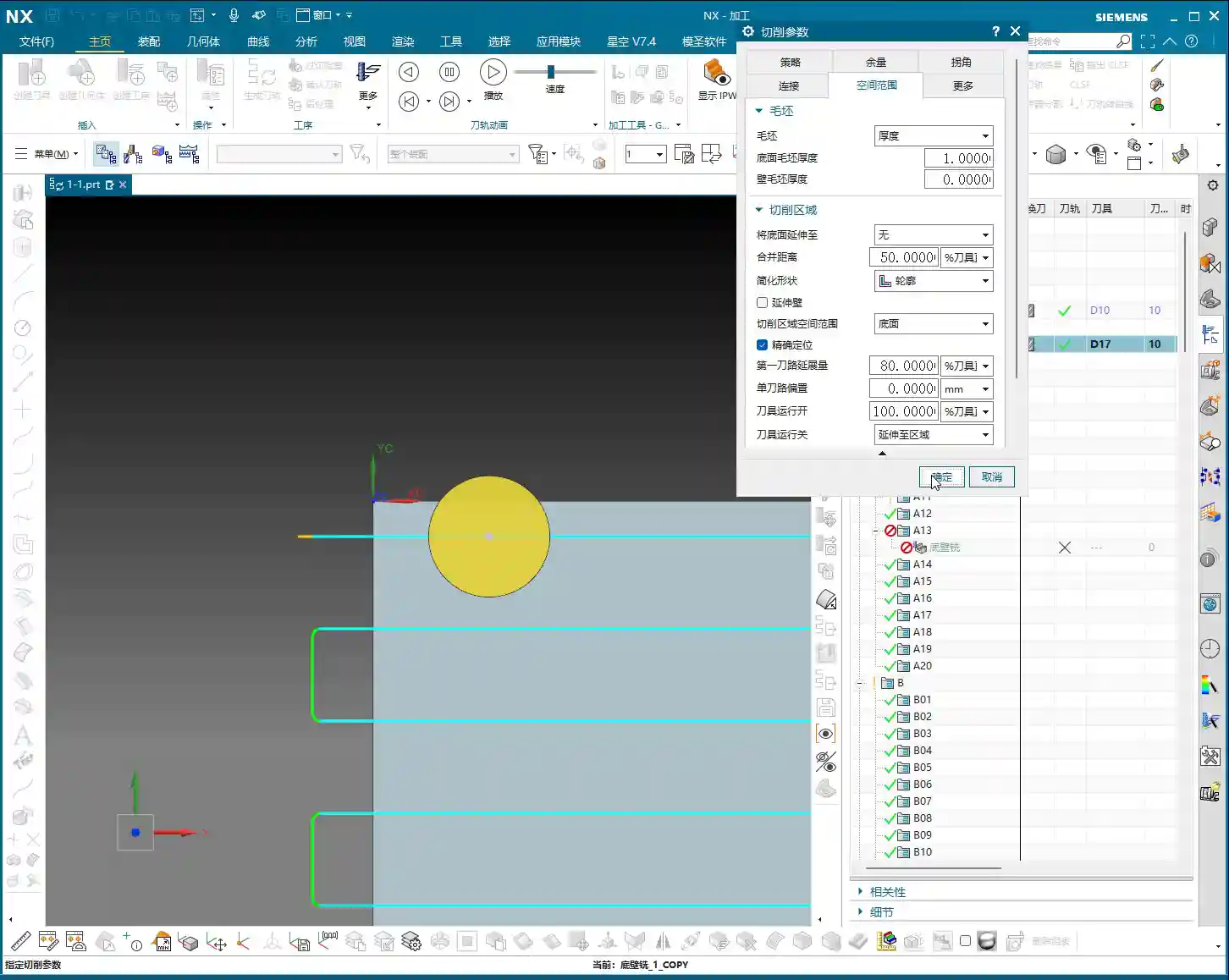
First Pass Extension Amount: Controlling the First Depth of Cut
This parameter is extremely critical, as it controls where your tool begins its first Depth of Cut. What does the default 55% mean? Look at the small diagram, and you’ll understand. It indicates that the tool’s center point is 55% of the tool radius away from the boundary. If you want the tool’s first cut to be exactly on the center line, you need to change this value to 50%. This way, the tool’s centerline aligns perfectly with the boundary, no more, no less – just right!
- Inward Shift: If you want the tool to start cutting from a position further inside the workpiece, for instance, to avoid burrs on the boundary during face milling, you can reduce this value. For example, changing it to 30% will make the tool ‘step’ inwards a bit, moving more conservatively. Even more aggressively, 20% or even 10% will bring the tool closer to the workpiece interior step by step.
- Skimming the Edge: If set to 0% (or close to 0, like 0.01%), theoretically the tool would follow the boundary tightly. However, in practice, this 0% might not always give you the desired effect, and sometimes the software might not even fully support 0, as it’s also linked to other parameters like tool retraction paths. So generally, we don’t use such extreme values.
- Outward Expansion: Conversely, if you want the toolpath to extend outwards, just increase the value. For example, 80% will make the tool travel further outwards. Remember, 50% is center-aligned; increasing the value (60%, 70%, 80%, 90%) expands outwards, while decreasing it (40%, 30%, 20%) retracts inwards.
Master Wang’s Tip: In actual machining, especially during face milling, we often need to control the position of the first pass. For example, to prevent chatter or chipping at the workpiece edge, we might reduce the first pass extension amount, making the tool engage from a more inward position. This reduces the impact on the material’s edge. Changing it to 30% or even 20% can result in better surface quality and longer tool life.
Single Toolpath Offset: Fine-tuning for Single Paths
This ‘Single Toolpath Offset’, as its name implies, is only effective when your program uses a single toolpath. For example, if you’re only making one pass in a narrow slot, you can use this parameter to offset the toolpath slightly upwards or downwards. It literally means to deviate from the centerline and move to one side. However, since most of our current programs are not purely single-pass, this parameter is rarely used. Just knowing it exists is enough; we’ll skip the detailed explanation for now.
Tool Motion Start: Not Commonly Used, But Good to Know
This parameter controls the starting point of the tool in the entire toolpath trajectory. For example, 100% means starting from the beginning, while 50% means starting from the halfway point of the toolpath. However, in conventional machining, we usually keep this parameter at 100%, meaning the full path is traversed. It doesn’t offer the same clear practical value as ‘First Pass Extension Amount’. If you want to experiment, feel free to change it, but typically, we skip it.
Practical Application of Space Range: Face Milling and Contour Control
Next, let’s use a face milling example to properly understand the different options for ‘Extend Bottom Face To’. This is crucial for improving efficiency in real-world applications!
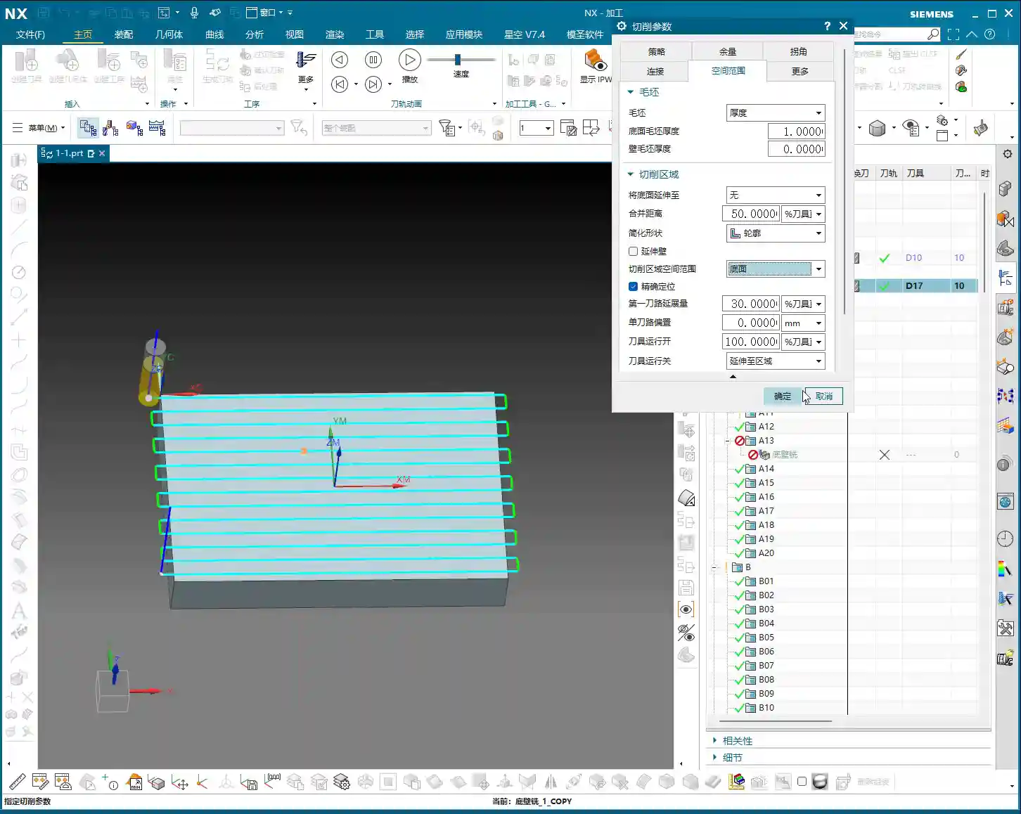
We’ll create a new face milling operation and select this bottom face for machining. By default, the toolpath might only follow the selected bottom face area, performing a zig-zag cut. You’ll find that the tool might only cut the middle of the workpiece, leaving areas untouched at the edges. This happens when the ‘Extend Bottom Face To’ parameter is not set correctly.
- “None”: When you select “None”, the tool will strictly machine according to the boundary of the bottom face you’ve selected. If your workpiece has chamfers or transitions at the edges, the tool won’t cross this boundary. This leads to the ‘incomplete machining’ problem we just discussed.
- “Part Contour”: This is the most commonly used option for face milling! By selecting “Part Contour”, the system automatically identifies the maximum outer contour of your chosen part. Even if you’ve only selected the middle of the bottom face, the tool will machine the entire surface area based on this maximum contour. This avoids issues with air cutting or incomplete machining. Remember, for face milling, prioritize ‘Part Contour’!
Master Wang’s Reminder: If you only select the bottom face and set ‘Extend Bottom Face To’ as ‘None’, the tool will only follow that specific bottom face. This might leave many unmachined areas, which is critical in mass production, leading to rework and material waste, driving up costs! Therefore, flexible use of ‘Part Contour’ is very important.
Merge Distance: Consolidating Scattered Toolpaths
The ‘Merge Distance’ parameter isn’t just found in face milling; it’s encountered in many other operations as well. Its function is simple: to combine your scattered toolpaths into a continuous path.
Look here, if I select three cutting areas, two of the toolpaths might be close enough to automatically merge into one. But if the other two areas are further apart, for example, they have a 100mm gap between them, they will run independently and won’t merge.
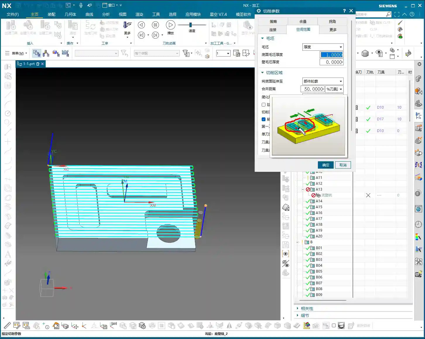
In this case, if you want them to merge, you need to input a value greater than 100mm into ‘Merge Distance’, such as 120mm. This way, the system will treat these two previously independent toolpaths as a single entity. The tool will not retract when moving between them but will travel continuously, significantly reducing air cutting time and improving efficiency.
Master Wang’s Experience: Using merge distance effectively can significantly reduce the tool’s idle travel, especially when machining parts with multiple dispersed features. The effect is particularly pronounced. Conversely, if the merge distance is set too small, the tool will frequently retract and engage, wasting time and increasing wear. Therefore, you must adjust it flexibly based on the actual spacing of the part’s features.
Bounding Box of Cut Area: Similar to Part Contour
The ‘Bounding Box of Cut Area’ actually yields the same results as ‘Part Contour’ in many situations. When you’re face milling a workpiece, selecting ‘Bounding Box of Cut Area’ will also make the toolpath cover the entire outer contour of the workpiece. It’s also a very practical option; generally, you can consider it equivalent to ‘Part Contour’. As long as it cleans the face and meets the requirements, use whichever is more convenient.
Final Defense: Check Tool and Holder for Collision
Finally, let’s talk about a life-saving parameter: ‘Check Tool and Holder for Collision’. This is extremely important, as it directly relates to the safety of your tool, fixture, and workpiece!
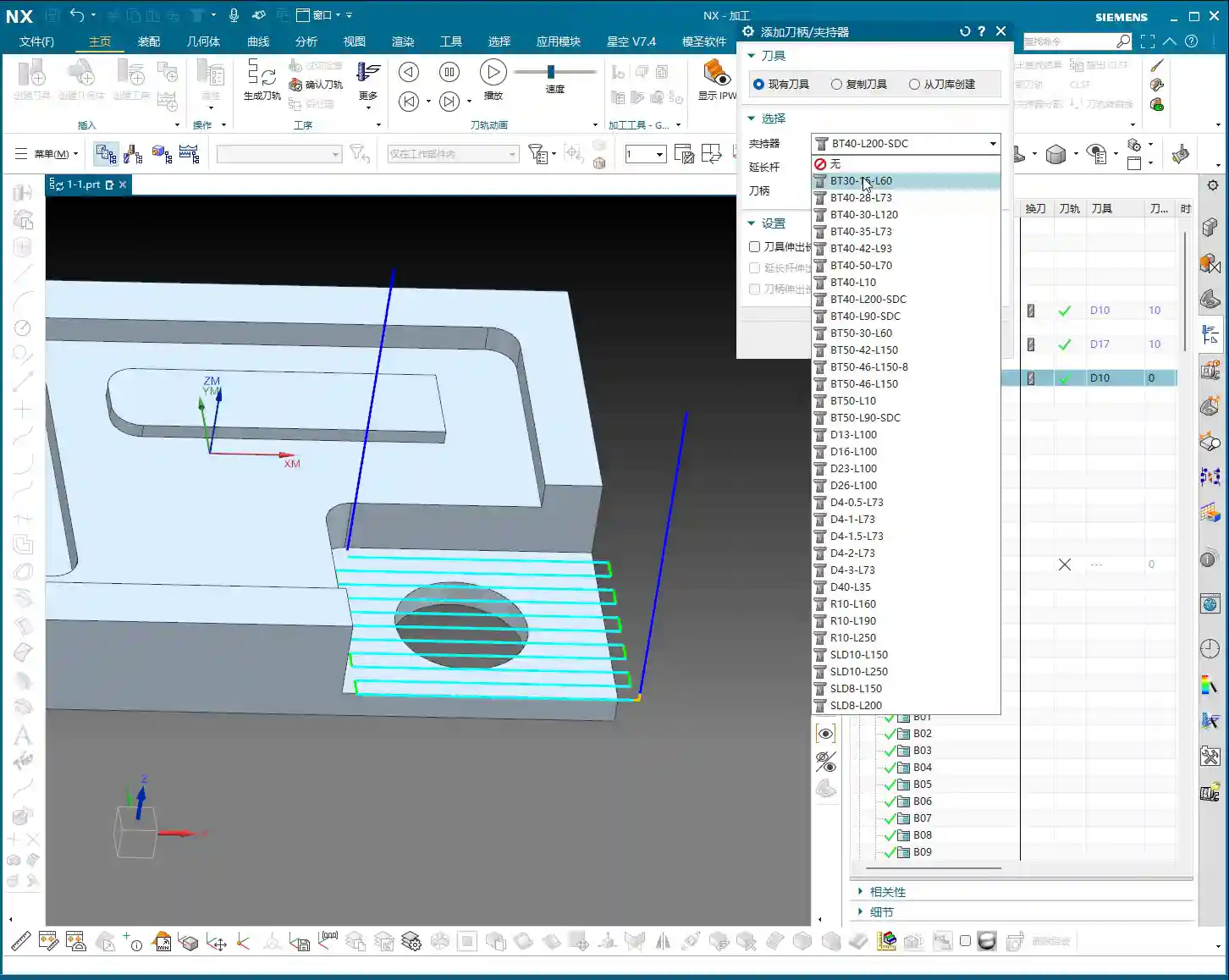
Let’s designate a face of a part as the machining area and generate the toolpath without initially considering the tool holder. Next, we need to insert a tool holder. In the program settings, find the ‘Set Holder’ option. Here, you have many standard tool holders to choose from. For example, let’s select a BT40 tool holder with a 50mm diameter. After confirming its addition, you’ll notice that while the tool holder is present, the actual protrusion length of the tool might be very long, which carries a huge risk of collision!
This ‘Check Tool and Holder for Collision’ option is precisely for alerting you. When checked, NX will help you inspect for interference between the tool, tool holder, fixture, and workpiece. If a collision is detected, it will issue a warning, or even prevent you from generating the toolpath, preventing you from making a rookie mistake. So, Master Wang, I emphasize this repeatedly: always pay attention to this option. It’s better to check it an extra time than to risk a machine ‘crash’!
Summary: Pitfall Avoidance Guide
- First Pass Extension Amount: Adjust flexibly during face milling to retract inwards, reducing edge impact and improving surface quality and tool life.
- Extend Bottom Face To: For face milling, always select Part Contour to ensure the entire machining area is cleaned, avoiding omissions.
- Merge Distance: Adjust based on actual workpiece feature spacing. Proper setting can significantly reduce air cutting and improve machining efficiency.
- Collision Check: Always enable it! This is the last line of defense against machine damage, scrapped tools, and scrapped workpieces. Don’t be lazy; safety first!
These are experiences I, Master Wang, have accumulated over years of practical work. You might not find them in textbooks, but they are lessons learned through hard-won experience. I hope you can grasp them well and apply them flexibly!