📝 Key Takeaways: Master Wang will guide you through the secrets of stepover settings in Siemens NX Cavity Milling, deeply analyzing the fundamental differences between ‘Constant Stepover’ and ‘Percentage of Tool Flat’ and their impact on toolpaths. We’ll also provide a practical demonstration of how to use slope analysis to accurately identify planar surfaces in parts, laying a solid foundation for developing efficient subsequent machining strategies. Master these techniques, and your toolpaths will become smarter, more efficient, and achieving higher precision will no longer be a challenge.
Alright lads, Master Wang here! Today we’re diving into some tough stuff in Siemens NX cavity milling: stepover and how to pinpoint the ‘planar surfaces’ in your parts. Don’t underestimate these parameters; if you don’t grasp them, your toolpaths will always be ‘good enough,’ leading to wasted tooling, lost time, and potentially scrapped parts.
Stepover: A Big Deal in How Your Tool Advances
Listen up. Simply put, ‘stepover’ is how much the tool shifts sideways after completing each pass. Don’t think it’s simple; there’s a lot to it. Siemens NX offers several stepover modes, but for us on the shop floor, you mainly need to understand these two common ones.
Constant Stepover: Simple, Direct, Ideal for Roughing
‘Constant Stepover’ is straightforward. You set a percentage, say 75%, and it calculates based on the entire diameter of your tool. For example, if you’re using a 25mm diameter tool and set it to 75%, each step will advance 25 * 0.75 = 18.75mm. This method is simple and direct; the tool moves quickly, making it suitable for roughing operations where efficiency is paramount.

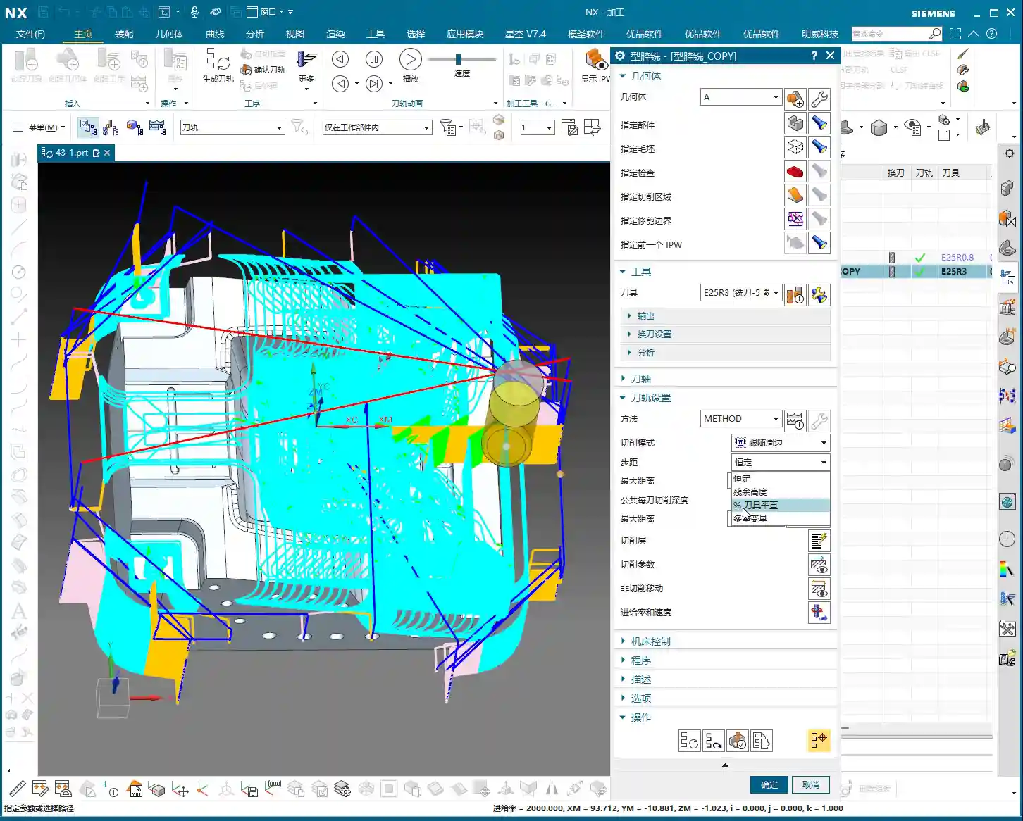
Percentage of Tool Flat: For Precision Finishing and Surface Quality
Now, ‘Percentage of Tool Flat’ is what we need to focus on for finishing passes. It’s different from ‘Constant Stepover,’ so don’t mix them up!

Let me give you an example: Say you’re using a Φ25R3 bull nose end mill. The R3 here is the tool’s corner radius. So, how wide is the actual ‘flat portion’ of this tool? It’s the tool diameter minus the two corner radii, which is 25 – (2 * 3) = 19mm.
If you set ‘Percentage of Tool Flat’ to 75%, then the calculated stepover will be 75% of that 19mm, meaning 19 * 0.75 = 14.25mm.

See the difference? Both are 75%, but one calculates to 18.75mm, and the other to 14.25mm. The latter has a smaller stepover, meaning more passes, and thus a smaller scallop height (uncut material), resulting in a naturally better surface finish. This is why we prefer ‘Percentage of Tool Flat’ for finishing passes. However, the toolpath will be longer, and machining time will increase – it’s a trade-off between efficiency and quality.
Normally, you can just default to ‘Percentage of Tool Flat’; it meets requirements in most situations.
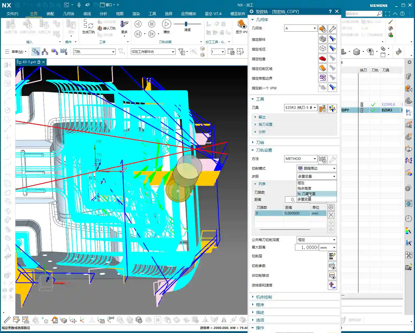
Constant Depth of Cut per Pass: Controlling the DOC
This setting controls how deep the tool cuts with each downward pass. For instance, if you set it to 1 millimeter, the tool will descend 1 millimeter each time. If set to 5 millimeters, it will, of course, cut faster. But here’s a pitfall: when you encounter a planar surface, this ‘scallop height’ can change. Sometimes you’ll find that even if you set 1mm, it suddenly takes a 5mm or even deeper DOC. What’s going on? This brings us to our next major topic.

Plane Recognition: Boosting Efficiency with Slope Analysis
Why does the tool sometimes behave ‘well,’ following a sequential path, while other times it ‘jumps’ to complete a step? This relates to your part’s geometric characteristics – planar versus non-planar surfaces. Identifying planar surfaces in a part is crucial for us to develop efficient machining strategies.

Why Identify Planar Surfaces? Machining Strategy is Key!
Listen up! If an area is a planar surface, then we can directly use ‘Face Milling’ or other more efficient strategies. The tool can take large stepovers, or even a flat-end mill can be used for direct clearing. But if it’s a non-planar surface, especially a contoured surface, then you must consider the scallop height (also known as ‘cusp height’). You’ll need to use a ball end mill or the corner radius of a bull nose end mill for finishing, requiring a smaller stepover, and the toolpath will be more complex.
Therefore, being able to instantly distinguish between planar and contoured surfaces directly impacts your programming approach and machining efficiency!

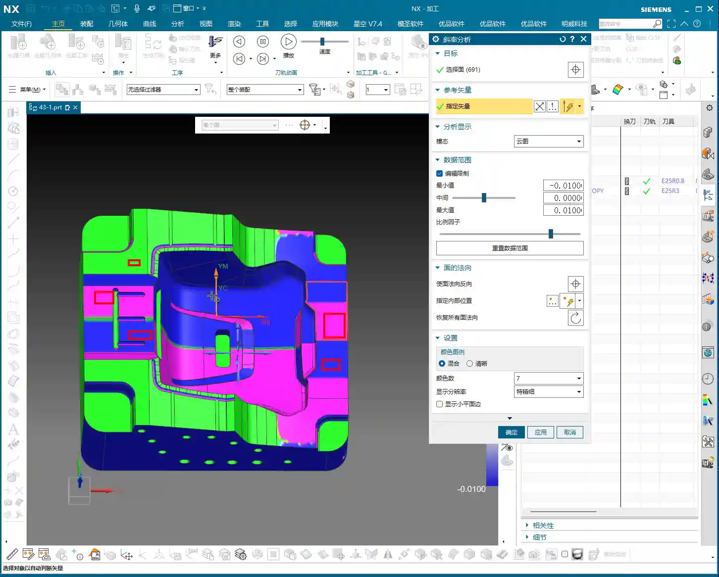
Siemens NX Slope Analysis in Practice: No Hiding for Planar Surfaces
In Siemens NX, we have a great tool called ‘Slope Analysis.’ This feature helps you quickly identify planar surfaces in your part model. It’s quite simple to use:
- Enter the analysis function and find the ‘Slope’ option.
- Select all the faces you want to analyze.
- Choose a ‘Reference Vector.’ Typically, we start by using the Z-axis direction (Z+ or Z-) as the reference.
- Check the results! Siemens NX will highlight planar surfaces that are ‘parallel to the reference vector’ (or rather, perpendicular to the reference vector) in green. These are the planar surfaces we’re looking for!
If some faces aren’t green, but you suspect they might be planar, then change the reference vector direction (e.g., Y-axis or X-axis) and analyze again. This way, you can find planar surfaces in all orientations.
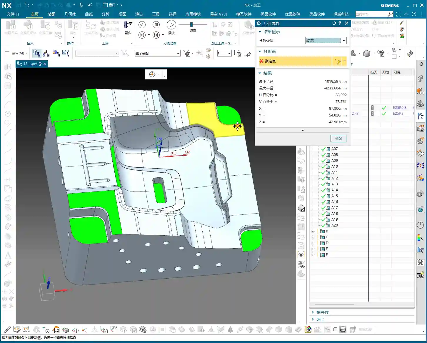
Property Verification: Constant Z-axis Value is Undeniable Proof
Just looking at colors isn’t enough; as a master teaching apprentices, I’ll show you how to truly verify. In Siemens NX, select a face you believe to be planar and then check its ‘Properties.’ If all points on this face have a constant Z-coordinate value (for example, all 8.75mm), then congratulations, it’s a genuine planar surface! If the Z-value varies even slightly, say ±0.005mm, then it’s not a standard planar surface; it might be a subtle angled surface or a contoured surface, and your machining strategy will need to change accordingly.
Through this method, we can not only identify planar surfaces but also determine their respective heights. Some planar surfaces might be at the same height, while others differ. This provides us with the basis for selecting appropriate tools and machining paths later on.


Scallop Height: We’ll Delve Deeper Next Time
Today, we’ve thoroughly covered stepover and plane recognition. As for ‘scallop height,’ which I mentioned earlier, that’s another extensive topic. Especially in non-planar areas, how to control tool marks and ensure surface finish – this parameter has many settings, and newcomers can easily get confused. We won’t expand on it in this lesson; in the next class, I’ll personally guide you through mastering ‘scallop height’!
Now, you lads need to practice diligently. Use ‘Slope Analysis’ to thoroughly examine your part models, find all the planar surfaces for me, and confirm their Z-coordinates. This is fundamental; with a solid grasp of the basics, you’ll be able to learn and effectively apply advanced techniques later on.
Summary: Pitfall Avoidance Guide
- Stepover Selection is Crucial: For roughing, choose ‘Constant Stepover’ for efficiency. For finishing passes, always select ‘Percentage of Tool Flat’; it more effectively controls scallop height and improves surface quality. However, understand that its calculation is based on the tool’s flat portion, not its full diameter.
- Slope Analysis, Your Planar Surface Identification Weapon: Stop relying on guesswork! Make good use of Siemens NX’s ‘Slope Analysis’ function. By combining it with different reference vectors, quickly and accurately identify all planar regions in your model. The green areas are your targets!
- Z-axis Property, Undeniable Proof for Planar Surfaces: Doubting if a face is planar? Open its ‘Properties’ and check if its Z-coordinate remains constant. Even a tiny variation in the Z-value indicates it’s not a purely planar surface and requires a different machining approach.
- Machining Strategy, Adapt to the Terrain: Clearly identifying planar versus non-planar surfaces allows you to select the most appropriate machining strategy during programming. This avoids using inefficient contour milling methods on planar surfaces, or aggressive face milling methods that could damage contoured details. It saves both time and tooling, while ensuring quality.
- Don’t Blindly Trust Default Parameters: All parameter settings must be adjusted based on the actual workpiece, tool, and machining requirements. Don’t just rely on software simulations; pay close attention to actual cutting sparks and tool marks.
👤 About the Author:
The author is a veteran CNC machining professional with 15 years of industry experience, specializing in UG NX programming. This article is an original work representing personal practical insights.
⚠️ Copyright Notice: Unauthorized reproduction or distribution without prior communication is strictly prohibited.