Tag: Streamline Machining

  • In-depth Analysis of Streamline Machining in Siemens NX: Master Wang’s Guide to Streamline Curve Sel

    📝 Key Takeaways: Master essential techniques for Streamline Machining in Siemens NX. Master Wang explains the “Specify” and “Automatic” selection methods for streamline curves, stressing the importance of consistent direction to prevent chaotic toolpaths. He reveals the practical insight that “Cross Curves” are optional in streamline operations. The discussion then deep dives into how cutting direction influences climb milling, conventional milling, upward/downward feed, and spiral toolpaths, alongside strategies for optimizing toolpath efficiency and quality through proper Stepover settings. Master Wang cautions against blindly trusting “Automatic” selection and advises adjusting parameters based on real-world observation of cutting sparks.

    Introduction

    Master Wang Speaks

    Hello everyone, I’m Master Wang. Today, we’re going to dive deeper into Streamline Machining in UG (NX). This area might seem straightforward, but it holds many intricacies, especially practical techniques not covered in textbooks that directly impact machining efficiency and part quality. Today, we’re going to thoroughly discuss the selection of streamline curves and the control of cutting direction. Pay close attention!

    Core of Streamline Operations: Streamline Curves and Cross Curves

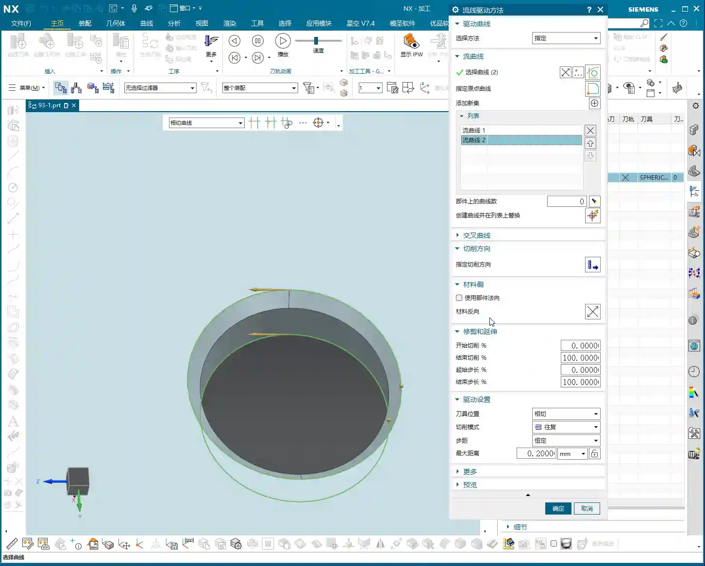
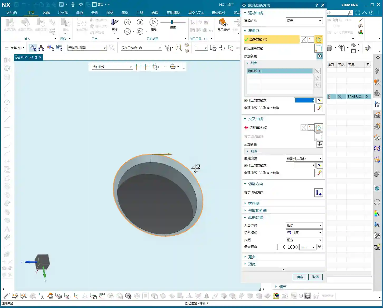
    “Selection Method”: Specify vs. Automatic

    In Streamline Machining, the first step is to define your “Selection Method.” You have two options: Specify and Automatic.
    Specify is straightforward: you manually select the curves, and the system only recognizes the lines you’ve picked. This is similar to how you select curves in “Cut Area.” If you’ve already selected “Isoparametric Vectors” in a “Surface Drive” operation previously, you might bypass this step because the logic is already fulfilled. However, for new projects or when precise control is needed, stick to the old rule: using “Specify” gives you peace of mind.
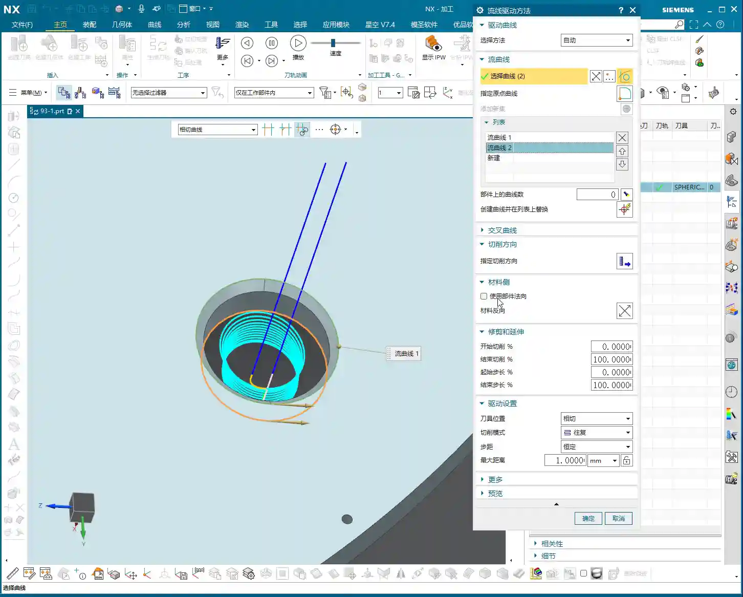
    Now, Automatic means the system identifies and selects the streamline curves itself based on your defined cut area. This can be convenient at times; just a click and it sets up the curves for you. But, listen up, “Automatic” doesn’t always select the curves you want! Sometimes, the lines it picks don’t match your intended toolpath direction or order, or they might not even be the specific curves you need. So, if your toolpath looks off after choosing “Automatic,” immediately go back and check, or simply switch to “Specify” and do it yourself—self-reliance is key.

    The Nuances of Streamline Curve Selection

    When selecting “Streamline Curves,” it’s the same concept as “Guide Curves” in “Guiding Curve” operations, typically Guide Curve 1 and Guide Curve 2. In practice, this corresponds to your Streamline Curve 1 and Streamline Curve 2. The key during selection is that the directions must be consistent! Otherwise, the program will become chaotic, leading to uneven toolpaths or even tool crashes.
    For example, if you select the first streamline curve and it has an arrow indicating its direction, then when you select the second curve, its arrow direction must also follow the first.

    • If both arrow directions proceed in the same manner (e.g., both left or both right), the generated toolpath will follow that trend.
    • If one goes left and the other goes right, your toolpath could become erratic or generate unexpected trajectories.

    This arrow direction directly determines whether you’ll be using Climb Milling or Conventional Milling, as well as the tool’s cutting order. Therefore, when selecting, always pay close attention to the arrows; double-clicking an arrow will reverse its direction, ensuring both streamline curves are aligned.

    Key Point: The Special Nature of Cross Curves

    Here’s a unique aspect that differs from other commands, so everyone take note! In a “Streamline” operation, Cross Curves are optional and do not need to be selected!
    Typically, with other commands, if an option isn’t checked, you absolutely have to select it or click on it; otherwise, the program might not generate or will produce an error. But here in Streamline, even if your “Cross Curve” option is unchecked, it’s perfectly fine; it won’t affect program generation or cause any errors. This feature can sometimes save a lot of trouble, as selecting cross curves can be cumbersome. So, if your machining doesn’t require it to constrain the toolpath, just skip it.

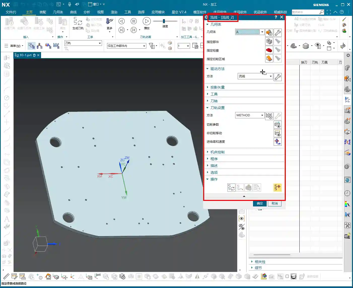
    Mastering Cutting Direction: Climb, Conventional Milling, and Toolpath Patterns

    Logic of Cutting Direction Selection

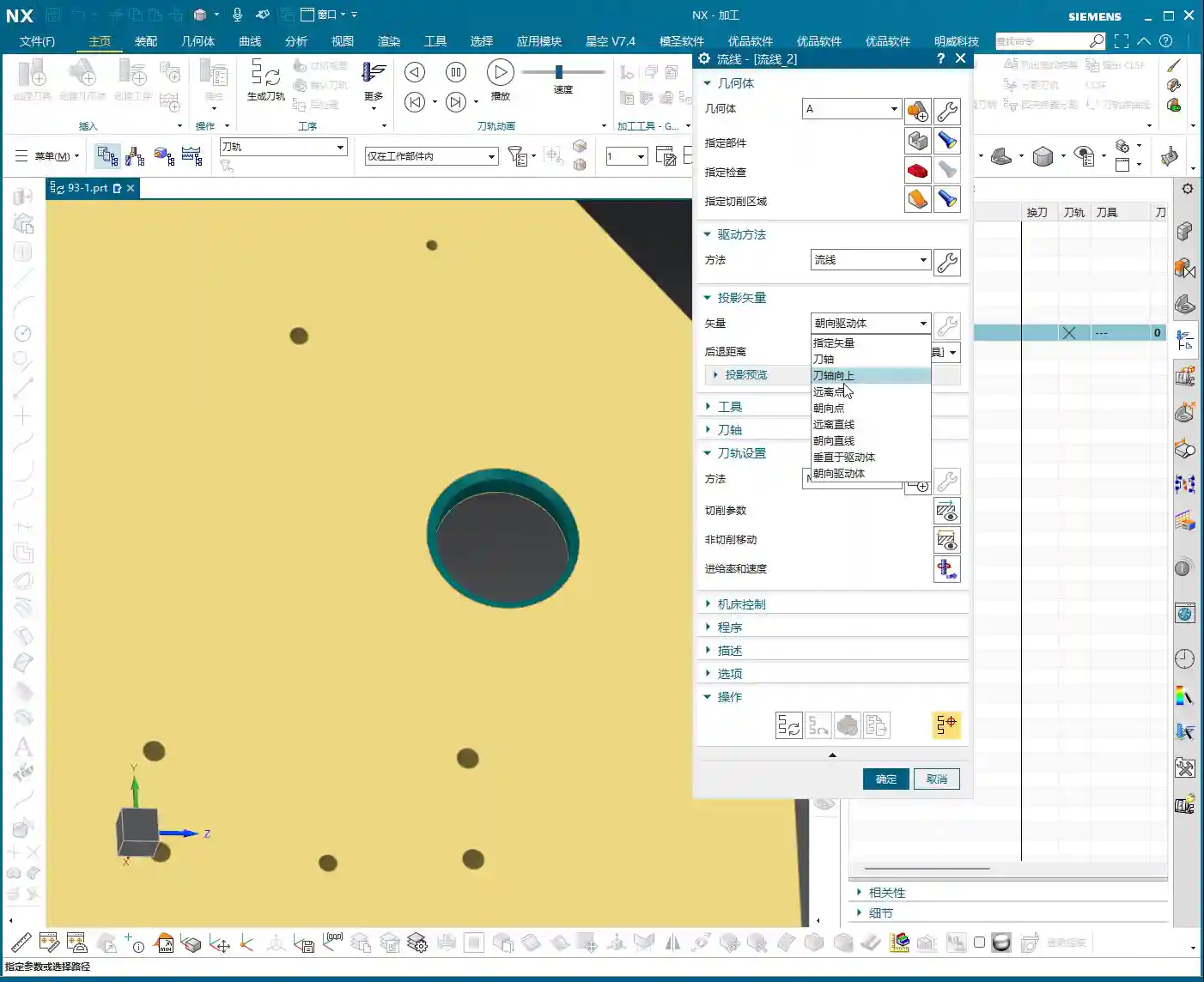
    The “Cutting Direction” parameter is a critically important aspect in real-world machining; it dictates how the tool engages the material and how it traverses.
    When you open the “Cutting Direction” options, several arrows will appear on the screen, allowing you to select the toolpath direction. Simply put, it controls two things:

    1. **Do you cut from top to bottom or bottom to top?**
    2. **Is it Climb Milling or Conventional Milling?**

    For instance, clicking the top arrow might correspond to “top-to-bottom” “Climb Milling”; clicking the bottom arrow might be “bottom-to-top” “Conventional Milling.” There’s no one-size-fits-all answer as to which is better; it entirely depends on your workpiece material, tooling, fixturing method, and final surface finish requirements.

    Climb Milling, Conventional Milling, and Feed Direction

    • Climb Milling: The tool’s rotation direction is consistent with the feed direction. Cutting begins where the material is thickest, and the chips exit from the thinner section. This typically results in better surface finish and longer tool life, suitable for most materials.
    • Conventional Milling: The tool’s rotation direction is opposite to the feed direction. Cutting begins where the material is thinnest, and the chips exit from the thicker section. This can lead to chatter and a relatively poorer surface finish, but for some materials with hard skins or for castings, conventional milling can sometimes yield unexpected positive results.

    In UG, selecting different arrows allows you to switch between these two cutting methods. When machining high-hardness materials like titanium alloys or high-temperature nickel-based alloys, the choice of cutting direction is critically important, directly impacting tool wear and machining stability. Don’t just rely on software simulations; observe the cutting sparks and listen to the machine’s sound – that’s where the real insights are!

    Toolpath Pattern and Cutting Direction Synergy

    The cutting direction also needs to work in harmony with your “Toolpath Pattern.” Common ones include:

    • Zig-zag: The tool moves back and forth, offering high efficiency, but the return pass might re-engage the material, potentially affecting surface finish.
    • Spiral / Planar Spiral: The toolpath follows a spiral pattern, typically used for pocket or circular feature machining, resulting in stable tool motion and good surface quality.

    For example, if you choose a spiral toolpath and also select a bottom-up cutting direction, the program will generate a toolpath that starts from the bottom and spirals upwards. If the chosen cutting direction conflicts with the logic of the spiral toolpath, the program might fail to generate, or it might produce an unusable toolpath.
    Master Wang reminds: When machining thin-walled or easily deformable parts, selecting the appropriate cutting direction and toolpath pattern, in conjunction with material properties and fixturing, can effectively reduce machining deformation and improve accuracy. Achieving ±0.005mm level precision often lies in these kinds of details.

    Stepover: The Secret to Optimizing Machining Trajectories

    Flexibly Adjusting Stepover to Enhance Observation Efficiency

    Stepover (or Step Distance), simply put, is the lateral or axial distance between each cut. If this value is set too small, the toolpath will be dense, leading to long machining times and low efficiency. If set too large, the machined surface will be rough, potentially showing noticeable tool marks.
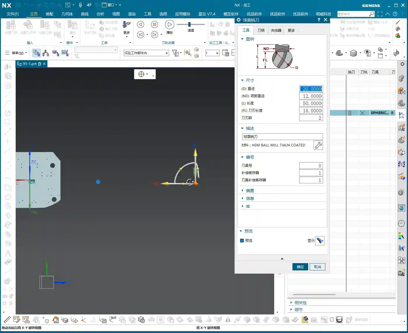
    During the program optimization phase, I often do this: to quickly visualize the toolpath’s overall direction, I’ll first set the stepover to a larger value, for instance, changing it from the default 0.2mm to 1mm (approx. 0.04 inch). This speeds up program calculation, resulting in a sparser toolpath, allowing me to quickly see if the overall path meets expectations and if there are any unusual moves. Once the overall direction is confirmed, I’ll then change the stepover back to an appropriate value for a finishing pass, such as 0.1mm (approx. 0.004 inch) or even 0.05mm (approx. 0.002 inch).
    Remember, adjusting the stepover is a common method for optimizing efficiency. Whether it’s roughing or finishing, you must adjust it flexibly according to the actual situation.

    Impact of Stepover on Toolpath

    Stepover directly influences the tool’s cutting load and surface quality.

    • **Roughing:** Stepover can be larger, prioritizing efficiency, but always mind tool life and machine load.
    • **Finishing pass:** Stepover must be small to ensure surface finish. Especially when machining molds, aerospace components, or other parts requiring high surface quality, fine-tuning the stepover is crucial.

    If your toolpath moves “from top to bottom, circle by circle” – a spiral trajectory combined with a ball nose end mill – it will naturally machine the sidewalls of the workpiece. The stepover setting then determines the machining texture and accuracy of the sidewall. The overlap between passes ensures the tool fully covers the machining area. All these parameters are interdependent and must be considered holistically.

    Summary: Pitfall Avoidance Guide

    1. **Streamline Curve Direction Consistency:** Whether you choose “Specify” or “Automatic,” it is crucial to verify that the arrow directions of all streamline curves are unified. Inconsistent directions are a common cause of chaotic toolpaths and reduced efficiency.
    2. **”Automatic” Selection is Not a Panacea:** While convenient, be wary of whether “Automatic” selection truly aligns with your intended machining strategy. Switch to “Specify” for manual calibration when necessary.
    3. **Special Handling for Cross Curves:** In Streamline Machining, Cross Curves are not mandatory. Decide whether to select them based on actual requirements to avoid unnecessary operations.
    4. **Strategic Cutting Direction:** The choice between “top-down/bottom-up” and “Climb Milling/Conventional Milling” directly impacts machining results, tool life, and part accuracy. Combine material characteristics, fixturing, and surface finish requirements to select the optimal direction. Exercise particular caution when machining intricate parts, thin-walled components, and high-hardness materials.
    5. **Flexible Stepover Application:** When debugging toolpaths, first increase the stepover for a quick preview; once confirmed, adjust it back to the small stepover required for the finishing pass. This is a practical technique for balancing efficiency and quality.
    6. **Combine Theory with Practice:** Software simulations are only a reference; the actual cutting sparks, sounds, and chip conditions provide the most genuine feedback. Observe frequently, summarize lessons learned, and only then can you truly become a master.

    👤 About the Author:
    The author is a veteran CNC machining professional with 15 years of industry experience, specializing in UG NX programming. This article is an original work representing personal practical insights.

    ⚠️ Copyright Notice: Unauthorized reproduction or distribution without prior communication is strictly prohibited.

  • NX Streamline Machining for T-Slots with T-Cutters: Practical Secrets to Solving Undercut Challenges

    📝 Key Takeaways: Master Wang explains practical techniques for NX Streamline machining of T-slots and T-cutter creation. The focus is on analyzing undercut features, emphasizing the advantages of Streamline operations in Surface Milling and T-slot machining. He provides a detailed demonstration of T-cutter parameter settings, such as diameter and cutting edge length, and offers practical considerations for projection vectors and retract distance. The “pitfall avoidance” guide highlights tool selection, meticulous parameter setup, practical observation, and toolpath optimization to tackle high-precision challenges.

    Streamline Machining: More Than Just a Basic Operation

    What’s the Point of Streamline Operations?

    Alright everyone, although this lesson is a re-recording, it’s packed with practical insights. Last time things were a bit disorganized, so this time, Master Wang will clarify everything for you. Listen up!

    **Streamline Machining**, to put it plainly, is our go-to tool for **finishing passes**. Especially when dealing with **complex surfaces** and **undercuts** (i.e., special shapes like T-slots), it has a distinct advantage over other operations. Remember, Streamline is primarily for **finishing passes**; you won’t need it for **roughing**. For roughing, stick to operations like Cavity Milling or Planar Milling – those are efficient. Finishing passes demand surface finish and accuracy, and Streamline is designed precisely for that.

    It can also machine **flow paths** and similar features, but its most common and valuable applications are these two: **Surface Milling for finishing passes** and **fine finishing of undercut areas**.

    What’s the Difference from Guiding Curves?

    Some might think Streamline Machining is similar to Guiding Curve machining, as both involve selecting guide lines for toolpath generation. Indeed, they look alike, and the core idea is to generate toolpaths along guide lines. However, Streamline Machining has a unique trick: it allows you to select **specialized tools** for machining, such as the **T-slot cutter** we’ll discuss today, or a **lollipop cutter** (which is essentially a ball nose end mill with a rounded head, specifically for small radii and deep cavities).

    This isn’t as flexible with Guiding Curves; many specialized tools aren’t supported. Therefore, when you encounter areas that standard tools can’t reach or would cause interference, **Streamline Machining combined with specialized tools** is your lifeline. Don’t just be impressed by fancy software simulations; you need to verify if the tool can complete the cut smoothly without collision during actual machining!

    Analyzing Undercut Features: Why the T-Slot Cutter Reigns Supreme?

    Workpiece Feature Analysis

    Let’s take a look at this part; don’t just focus on the shiny surface, look deeper! This undercut hole isn’t straight up and down; it’s an **angled hole, a normal hole**. If you look closely, you can’t see the bottom sidewall of this hole, right? This is a typical **undercut feature**. In such areas, a standard flat end mill or ball end mill simply can’t enter, or if it does, it won’t cut the bottom cleanly, will damage the sidewalls, or even break the tool directly. That’s no laughing matter.

    Therefore, for this kind of feature, we must use a **T-slot cutter** for machining. For **roughing**, you can be a bit more flexible, using a smaller flat end mill or ball end mill to clear some material first. But for the **finishing pass**, you need to switch to the right tool; a T-slot cutter is the correct solution. This is practical experience; you might not find such detail in textbooks.

    NX Streamline Machining Parameter Settings

    Basic Operations: Specify Part and Cut Area

    Okay, open the Streamline operation.

    1. **Specify Part**: I don’t need to elaborate on this, right? Select your workpiece; this is fundamental. Any machining operation requires you to first tell the software which part you intend to machine.
    2. **Cut Area**: You must select this correctly. If you want to machine a specific face, like this angled undercut surface, then make sure you select *that* exact face. Don’t get sloppy and choose the wrong one. If you select incorrectly, the toolpath will go where it shouldn’t, leading to wasted machining at best, and a tool collision at worst.

    Drive Method: Select Streamline

    For **Drive Method**, just select **”Streamline”**. Why? Because we’re learning Streamline right now, choosing anything else would be off-topic, haha. Of course, NX has many drive methods, each with its own application, but today’s star is Streamline because it handles complex surfaces and undercuts more effectively.

    Projection Vector: Practical Considerations and Efficiency Balance

    The **Projection Vector** generally defaults to **”Towards Drive Body”**. What does that mean? Simply put, the tool’s center point or tool axis will be projected onto your selected drive surface according to a certain direction. For example, if you select a planar surface as the drive body, the toolpath will project onto that plane, and that becomes the reference surface for the tool’s motion trajectory. For our undercut, it projects onto its angled surface, allowing the tool to follow that angled path.

    There’s also the **Retract Distance**, which is the distance the tool maintains from the drive surface after projection. Under normal circumstances, just **use the default value**; don’t blindly change it. If you don’t understand its specific function or haven’t thoroughly validated it, haphazard changes will only increase the risk of problems, potentially leading to overcutting or undercutting. When we cover more advanced settings and details later, you can adjust it based on actual needs and process requirements. Remember, **safety first, efficiency second**. If a problem can be solved with default values, don’t try to be clever and change them, just to add unnecessary risk.

    T-Slot Cutter Creation and Parameter Configuration

    Why Choose a T-Slot Cutter?

    As mentioned earlier, for special shapes like **undercuts**, a **lollipop cutter** can also be used because its rounded head can, to some extent, handle chamfers. However, the results will certainly not be as clean and thorough as with a **T-slot cutter**. The cutting edge design of a T-slot cutter is specifically for machining sidewalls and bottoms, allowing for more complete material removal and ensuring accuracy and surface finish. A **lollipop cutter** is better suited for undercuts with a rounded bottom and sidewalls that allow for a small inclination angle, whereas a **T-slot cutter** is specifically designed for undercuts with right-angle or near-right-angle features.

    Don’t be fooled by the variety in the NX tool library; the key is to choose the right one and understand each tool’s purpose and limitations. Selecting the wrong tool isn’t just a waste of time; it can directly lead to scrapped parts, or even damage to the tool and machine!

    T-Slot Cutter Creation and Key Dimensions

    Alright, let’s create a new **T-slot cutter**. I won’t change the name; just confirm it. The parameters are what’s important! These aren’t just arbitrary numbers; they are determined by the **drawing requirements** and **actual working conditions**.

    1. **Tool Diameter (D)**: This must be determined by your undercut width. For example, let’s first set it to **12 mm (approx. 0.47 inch)**. Hmm, that looks a bit small, not enough to cut. Let’s make it larger, **16 mm (approx. 0.63 inch)**; this size should roughly cover the undercut width. If it’s too large, it won’t fit; if it’s too small, machining efficiency will be low, and it’ll be prone to chatter, leading to unstable cutting.
    2. **Shank Diameter (d)**: This must be smaller than the tool diameter to allow it to enter the undercut. For example, **10 mm (approx. 0.39 inch)** or **8 mm (approx. 0.31 inch)**, depending on the actual situation, as long as it avoids interference with the upper part.
    3. **Cutting Edge Length (L1)**: This is the length of the T-slot cutter’s horizontal cutting edge, which must ensure it covers the entire cutting range of the undercut. For example, **6 mm (approx. 0.24 inch)**. If this length is too short, it will leave residual material; if it’s too long, it might affect rigidity.
    4. **Overall Length (L)**: This is determined by your fixturing and workpiece depth; you need to leave sufficient safety clearance. For example, **50 mm (approx. 1.97 inch)**. This ensures the tool can reach the cutting position without extending too far and compromising rigidity.
    5. **Corner Radius (R)**: T-slot cutters typically have a small corner radius at the bottom to prevent stress concentration and enhance tool strength. For example, **R0.5 (approx. 0.02 inch)** or **R1.0 (approx. 0.04 inch)**. Refer to the drawing requirements for specifics.

    One more thing: after creating a T-slot cutter in NX, its default orientation might be incorrect. You need to **rotate it by 90 degrees** so that its horizontal cutting edge faces the workpiece’s cutting direction. This is crucial; if the orientation is wrong, the tool won’t function as a T-slot cutter but merely as a cylindrical end mill, completely unable to machine undercuts.

    Summary: Pitfall Avoidance Guide

    * **Tool selection is the absolute core**: When encountering features like **undercuts, T-slots, or deep cavity sidewalls**, your first thought should be a **T-slot cutter** or a **lollipop cutter**. You must determine which is more suitable based on the specific geometry. Force-fitting a conventional tool can, at best, trigger software alarms; at worst, it will lead to broken tools, scrapped parts, or even machine damage – and those losses can be significant.
    * **Parameter settings must be precise; don’t change them if you don’t understand**: While NX has many parameters, each has its practical significance. Especially for things like **Projection Vector and Retract Distance**, if you don’t understand their principles and effects, stick with the default values. Blindly modifying them is strictly forbidden. Incorrect parameter settings are a common cause of machining accidents.
    * **Combine theory with practice; pay attention to shop floor performance**: Don’t just rely on good software simulations; those represent ideal conditions. During actual machining, **cutting sparks, sound, chip shape, and machine load** are all crucial indicators for assessing cutting conditions. Observe closely, think critically, and be adept at adjusting the process based on real-world feedback – that’s genuine skill.
    * **Optimizing toolpaths saves costs; efficiency is the lifeline**: Streamline Machining, when combined with appropriate tools and parameters, can effectively **reduce air cuts** and avoid unnecessary redundant paths, thereby boosting machining efficiency. Time is money, especially in mass production; even minor toolpath optimizations can lead to significant cost savings and increased benefits.
    * **High precision demands meticulous attention to detail**: For high-precision requirements like ±0.005 mm (approx. ±0.0002 inch), no step can be overlooked. From the **rigidity of workpiece clamping, the wear status of the tool, the matching of cutting parameters, to the machine’s own accuracy compensation**, all can be critical factors affecting the final outcome. Experience is valuable, but even more important are **mastery of details** and **problem-solving capabilities**.

    👤 About the Author:
    The author is a veteran CNC machining professional with 15 years of industry experience, specializing in UG NX programming. This article is an original work representing personal practical insights.

    ⚠️ Copyright Notice: Unauthorized reproduction or distribution without prior communication is strictly prohibited.