📝 Key Takeaways:
Siemens NX Surface Milling in Practice: In-depth Analysis of Drive Geometry, Cut Direction, and Scallop Height
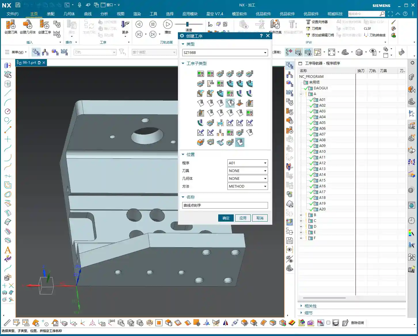
Drive Geometry: Defining the Machining Area is the First Step
“Drive Geometry Not Specified”? Listen Up, This is Fundamental!
Hello everyone, I’m Master Wang. Today, let’s continue discussing NX machining. Right off the bat, you might see the software prompt “Drive Geometry Not Specified.” It’s common, don’t panic.
Simply put, this “drive geometry” tells the machine which surface or area you intend to machine. You can’t just let the tool run wild, can you? So, you absolutely must select it!
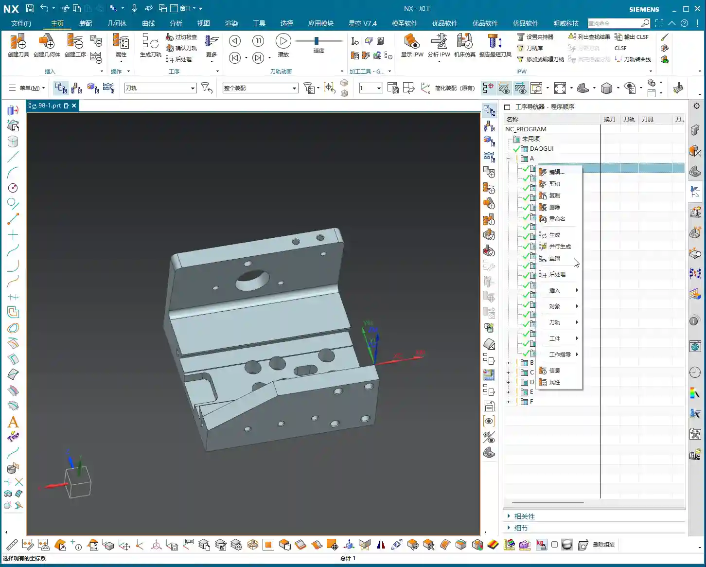
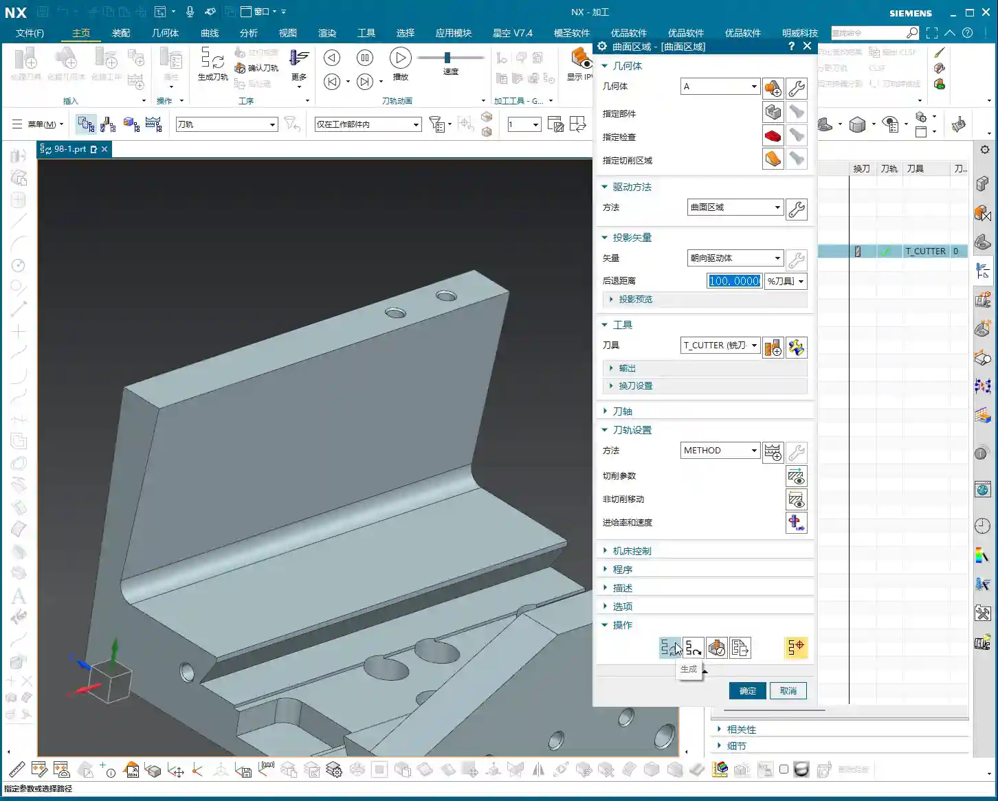
Practical Case Study: Tool and Workpiece Interaction, Smart Selection is Key
Take this example we have. If your tool radius matches the radius of the surface you’re machining, say both are R5 fillets, then you don’t need to select multiple surfaces. Just select this one surface as the drive geometry. It’s simple, direct, and maximizes efficiency.
Cut Direction and Material Side Reversal: The “Soul” of the Tool Path

Material Side Reversal: Mastering the Tool’s “Opening Move”
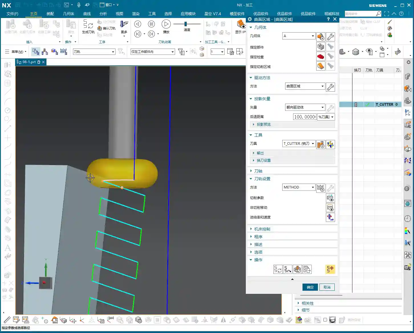
Once the program is generated, you need to observe where the tool starts its cut. Sometimes, it might begin from an undesirable location. This is where “Material Side Reversal” comes in. This concept is similar to what we discussed in the last lesson regarding “Flowline.”
Its purpose is to control which direction the tool starts machining the workpiece from. If the arrow points left, the tool starts from the left. If it points right, it starts from the right. Just click the small arrow to the desired direction for where you want the tool to engage. Don’t underestimate this; it directly impacts tool path planning and cutting stability.
Cut Direction: The Key to Determining the Machining Path
I must emphasize this “Cut Direction” again—it’s extremely important! It directly determines whether your tool moves up-and-down, left-and-right, or diagonally. Don’t just rely on the software simulation; observe its actual cutting path. See those little arrows? Click one, and the tool path instantly changes.
- If you select the top arrow, the tool might move from top to bottom.
- If you select the side arrow, the tool moves from this side to that side.
- If you select the bottom arrow, it machines from bottom to top.
Master Wang’s Tip: Different cut directions significantly impact surface finish and tool wear. On some complex surfaces, intelligently choosing the cut direction can noticeably reduce air cuts, improve machining efficiency, and even equalize cutting forces, extending tool life.
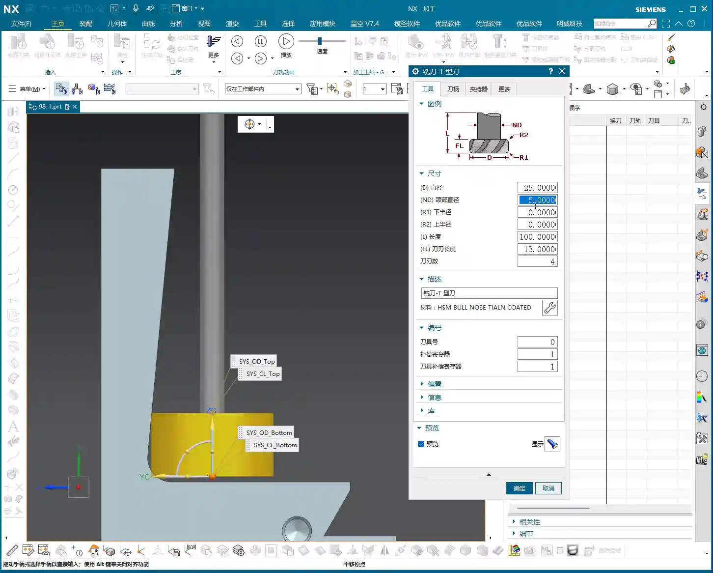
Tool Position and Surface Offset: Finishing and Stock Allowance Control

Tool Position: Tangent and Center
Here are two options: “Tangent” and “Center.”
- Tangent: The edge of the tool is tangent to your selected drive geometry. This is typically used for roughing or when a stock allowance is required.
- Center: The centerline of the tool aligns with the drive geometry. This is generally used for finishing passes, or when you want the tool center to pass directly through a specific point or line.
We’ve covered these two concepts in the “Flowline” lesson; they are fundamentals, so take some time to review them.
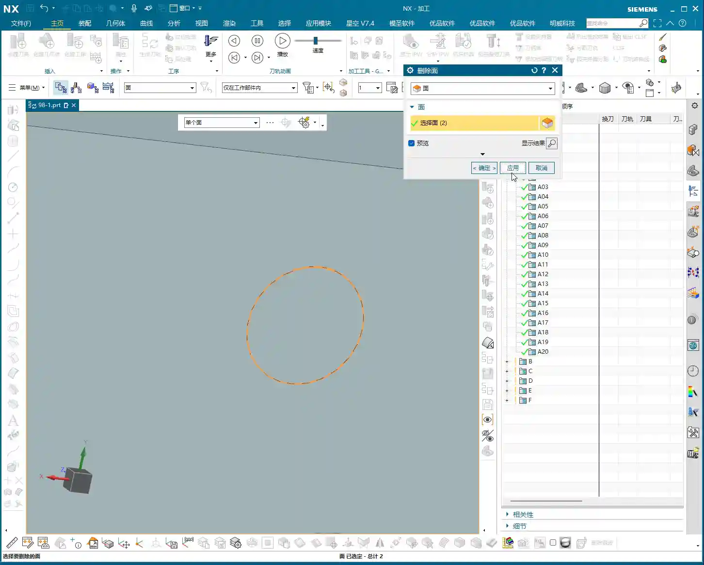
Surface Offset: Leaving “Room” on the Sides
What does “Surface Offset” mean? Simply put, it’s creating a gap between the tool and the surface you’re machining, essentially the same as “side stock allowance” or “radial stock.” If you input 1 mm, the tool will be 1 mm away from that surface. For roughing, you might leave a larger allowance, then set it to zero for finishing, or leave a finishing allowance.
Practical Tip: Flexible use of surface offset can save you the trouble of repeatedly selecting different geometries. It allows direct control over machining allowance, enabling multi-stage machining with a single setup.
Cutting Pattern: Choosing the Right Machining Rhythm

Analyzing Various Modes: Spiral, One Way, Zigzag, Follow Periphery
We’ve discussed cutting patterns many times before, so here’s a quick recap:
- Zigzag: The tool moves back and forth, offering high efficiency but uneven cutting forces, which can affect surface quality.
- One Way: The tool cuts in one direction, then retracts and returns for the next cut. This provides good surface quality but involves more retracts, leading to relatively lower efficiency.
- Spiral: This pattern is typically suitable for enclosed areas with a center hole, as it allows for continuous, non-retracting tool paths. However, if your workpiece has open areas, a spiral tool path might not be ideal and is not recommended.
- Follow Periphery: As the name suggests, the tool follows the peripheral contour of the workpiece. Since we’re dealing with an open area here, it’s not suitable.
Pitfall Alert: When selecting a cutting pattern, always base it on the workpiece’s geometry and machining requirements. Using the wrong pattern can lead to low efficiency at best, and a scrapped workpiece at worst.
Stepover and Scallop Height: The Core of Controlling Machining Accuracy and Efficiency
The “Number” of Stepover Trap: Don’t Just Look at the Number, Calculate it Precisely
When it comes to “stepover,” many people directly look at the “quantity” option and assume that entering a number means that many cuts. Listen closely, there’s a small trap here: when you enter a stepover quantity of 10, it actually performs 11 cuts! That’s because the first cut isn’t counted; it’s “1 plus 10”!
If you input 20 cuts, it becomes denser; 50 cuts, even denser. But the problem is, if you only input the quantity, you don’t know the actual depth of cut for each pass, do you? You’d have to calculate the total height divided by the number of cuts yourself. How cumbersome is that? And inaccurate calculations will affect the machining result.
Master Wang’s Insight: Relying on guesswork for stepover quantity will never achieve optimal surface quality and efficiency. That’s why we need to introduce the concept of “scallop height.”

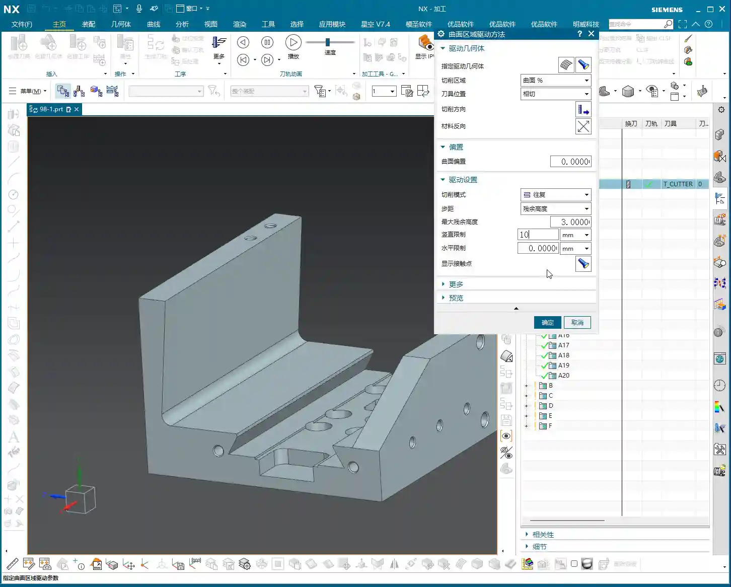
Scallop Height: The Core Parameter for Intuitive Control of Surface Quality
Previously, we often overlooked the “Maximum Scallop Height” parameter. Today, let’s discuss it thoroughly. This “Maximum Scallop Height” is truly the key to controlling the “stepover” between each cut! It directly determines the height of the tool marks left on the machined surface, also known as the size of the “fish scale pattern” or cusps.
Think about it: if you’re aiming for a high surface finish, this scallop height needs to be set smaller, for example, 0.01 mm. This results in a very dense tool path, and the surface will be smoother. If it’s roughing, you can set it larger to increase speed.

Precision Control: By mastering the maximum scallop height, you can truly achieve precise control over the workpiece’s surface quality, rather than relying on luck or “good enough.”
Vertical and Horizontal Limits: Defining Each Depth of Cut, Eliminating Ambiguity
Distinguishing “Vertical” from “Horizontal”: Machining Direction is Key
Now, let’s look at “Vertical Limit” and “Horizontal Limit.” Many newcomers get these confused. It’s actually quite simple:
- Vertical: This refers to directions like top-to-bottom or bottom-to-top. For instance, machining a vertical sidewall is a vertical cut.
- Horizontal: This means flat, parallel to the ground. For example, machining a planar surface.
The kind of tool path we’re currently discussing, moving from top to bottom, is a vertical cut. Since it’s vertical, your “Vertical Limit” setting will be effective! For example, if I set the vertical limit to 4 mm, then you’ll see that each cut precisely steps down 4 mm, clear as day.
Conversely, if your machining direction is horizontal, changing the “Vertical Limit” will be completely useless! It’s not cutting in the vertical direction, so changing it is pointless. You absolutely must distinguish this!
Master Wang’s “Universal” Fail-Safe Method: If You Can’t Tell, Do This!
I know that sometimes the workpiece geometry is too complex, or you lack experience, and you just can’t figure out if it’s vertical or horizontal. No worries, Master Wang will teach you a “universal” troubleshooting method:
If you truly can’t distinguish, just set both the “Vertical Limit” and “Horizontal Limit” to a very small value, such as 0.2 mm (approx. 0.008 inch). This way, whether it’s a vertical or horizontal cut, each depth of cut (or lateral stepover) will be restricted to within 0.2 mm, ensuring machining accuracy and surface quality. A program generated this way will definitely be problem-free, definitely correct! Even if you don’t fully understand it, you’ll still reliably get the job done.
Summary: Pitfall Avoidance Guide
Alright, we’ve covered quite a few hard-hitting topics today. Let me summarize some key points for avoiding pitfalls:
- Drive Geometry: Must be selected! Only by choosing the correct area will you machine the right place.
- Material Side Reversal and Cut Direction: These are the “batons” for your tool path. To control where the tool starts and where it moves, click the correct arrows; don’t let the tool wander aimlessly.
- Surface Offset: This is your side stock allowance; set it flexibly for roughing and finishing stages.
- Cutting Pattern: Choose based on the workpiece’s open/closed nature and surface requirements. Don’t carelessly use “Spiral” in open areas.
- Stepover and Scallop Height: These are core to controlling accuracy and efficiency. Don’t just look at the stepover quantity; focus on “Maximum Scallop Height” as it directly determines your surface quality.
- Vertical and Horizontal Limits: Understand whether you’re machining a “vertical” or “horizontal” surface. If you can’t tell, Master Wang’s universal method is to set both to a small value (e.g., 0.2 mm / approx. 0.008 inch), guaranteeing your output will be problem-free!
These are practical tips that textbooks might not fully explain. Go back and practice more. Once you’ve mastered these parameters, your Siemens NX Surface Milling skills will truly advance to the next level.
Next lesson, we’ll discuss “Surface Percentage,” an advanced feature. That’s all for today, see you next time!
👤 About the Author:
The author is a veteran CNC machining professional with 15 years of industry experience, specializing in UG NX programming. This article is an original work representing personal practical insights.
⚠️ Copyright Notice: Unauthorized reproduction or distribution without prior communication is strictly prohibited.