📝 Key Takeaways: Master Wang gives you an in-depth look at the core functions of ‘Tool Axis’ and ‘Cutting Method’ in UG NX 1980. From basic concepts to practical applications, learn how to precisely set the tool axis direction, master different cutting methods, avoid common filter pitfalls, and ensure efficient, stable machining paths.
Hello everyone, I’m Master Wang. Today, let’s continue discussing core operations in UG NX, especially the two key points: Tool Axis and Cutting Method.
Program and Blank Preparation
We’ve already covered tools, so today we’ll dive right into hands-on practice. First, we need a part to machine. Listen up, this is our actual component. The initial blank (raw material), I enclosed it directly with a block.
Select this block, select all, set its position to zero, confirm. When we first cut the blank, it was exactly this size, with the part inside, right?
First Operation: Face Milling
For the first step, we need to face mill this surface, which means flattening the top surface. Let’s see how DPM (Direct Path Manufacturing) performs this face milling.
Double-click to open the program. We can copy a program we’ve made before. For example, copy it into A02, right-click ‘Paste Inside’, and it’s there.
Blank Selection and Transparency
Double-click to open. If it prompts you to specify a component, just close it. Specifying only the blank is fine, or you can box-select both. Let’s just select this face of the blank, confirm.
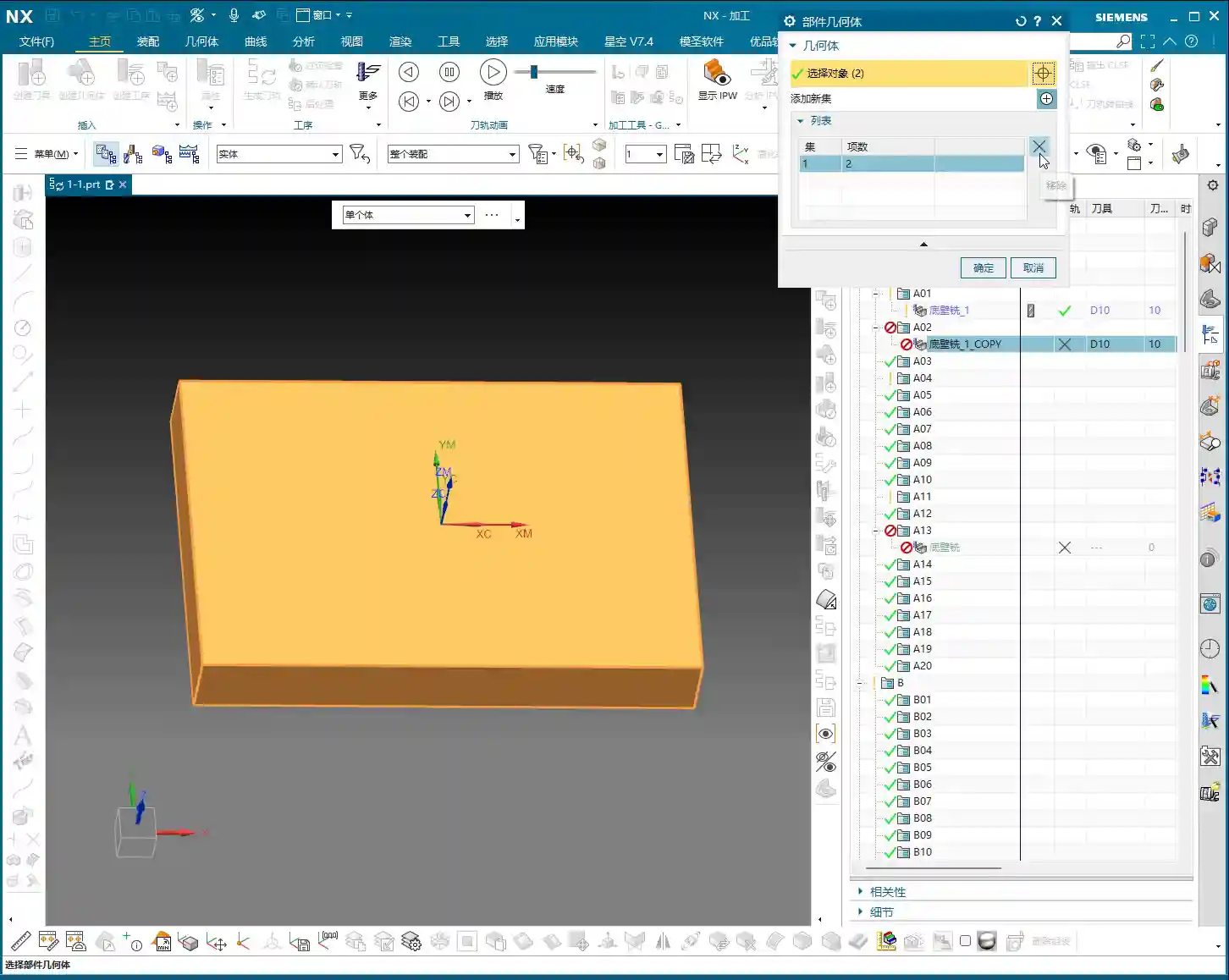
Some might not understand why the blank appears semi-transparent. That’s because after it’s created, its transparency isn’t very high. To adjust transparency, press Ctrl + J, or click ‘Edit Object Display’ nearby. Drag the slider, and you’ll see the solid blank.
To better observe the face milling effect, we can hide the part first. Click ‘Hide’, then ‘Invert Display’, and the part will be hidden.
Double-click to open again. When specifying the component, we’ll select the top face of this newly created block blank, confirm. Once the blank and tool are selected, the program should appear, right?
Toolpath Display and Filter Application
Pause the program. Now you can click anywhere on the toolpath, and it will jump to that position. Why can you click anywhere? Because our filter is set to ‘Toolpath’.
If you’re on the current page and click the program, it will be displayed; if you click other folders, then this toolpath will be hidden. So, click the toolpath you want to see, or click upwards, any will select it.
But pay attention: if your filter is set to another type, like ‘Drafting Filter’, you won’t be able to click on the toolpath. Only when the filter is ‘Toolpath’ or ‘No Selection Filter’ will you be able to click on it.
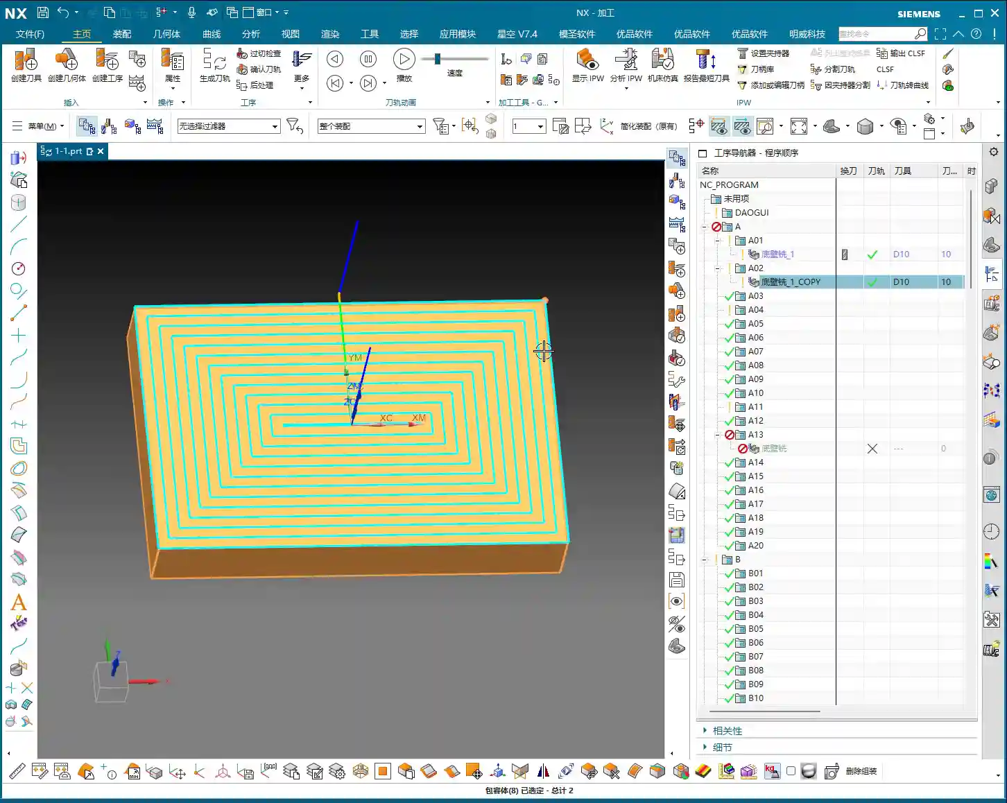
Three Highlighted Key Points
Also, these three areas, everyone must pay attention: they must be highlighted. If the middle one isn’t highlighted, you won’t be able to click the toolpath; if the two at the back aren’t highlighted, your rapid move lines or the entire toolpath will disappear, and you won’t see them at all. Usually, all three are highlighted, which ensures you can view and operate the toolpath normally.
Tool Axis Explained
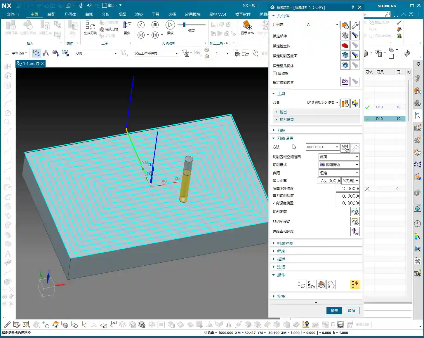
Let’s double-click to open and look at the ‘Tool Axis’ below.
Default Tool Axis: Perpendicular to First Face
Currently, the tool axis here is ‘Axis perpendicular to first face’. Why? Because for operations like Floor Wall Milling, its default tool axis is perpendicular to the first face. Usually, we don’t need to change it.
Common Tool Axis: +ZM Axis
Generally, during normal machining, it’s mostly the +ZM Axis. Except for Floor Wall Milling, most other commands, ninety-nine percent, use the +ZM axis.
The meaning of this is that our tool axis is upwards, meaning the Z-axis is upwards, machining from top to bottom. This is how +ZM axis machining works.
When learning 3-axis machining, it’s basically all about the +ZM axis. Almost all programs are like this. However, for special cases like Floor Wall Milling, setting it perpendicular to the first face is also acceptable.
When to Modify Tool Axis
Everyone should now understand the meaning of the tool axis. We mainly need to change it when learning 4-axis or 5-axis simultaneous machining. For 3-axis machining, we generally don’t need to adjust it much.
Cut Region Space Range: Bottom Face
Let’s look further down at ‘Cut Region Space Range’ and ‘Bottom Face’.
Looking at this diagram, there’s ‘Bottom Face’ and ‘B’. I personally think this ‘B’ method is used quite rarely. Because when we later learn 3D machining, we can directly machine sloped surfaces like this. This ‘B’ is specifically for machining sloped surfaces.
Floor Wall Milling is typically for 2D machining. While it can occasionally machine 3D (sloped surfaces), I don’t think the results are particularly good. So, I don’t really recommend using this function. Everyone just needs to know that such a function exists.
Typically, we will choose Bottom Face. This way, it directly machines up to this edge, and sloped areas are not machined.
Cutting Method Explained
Moving on, let’s look at our ‘Cutting Method’. Currently, the default is ‘Follow Perimeter’.
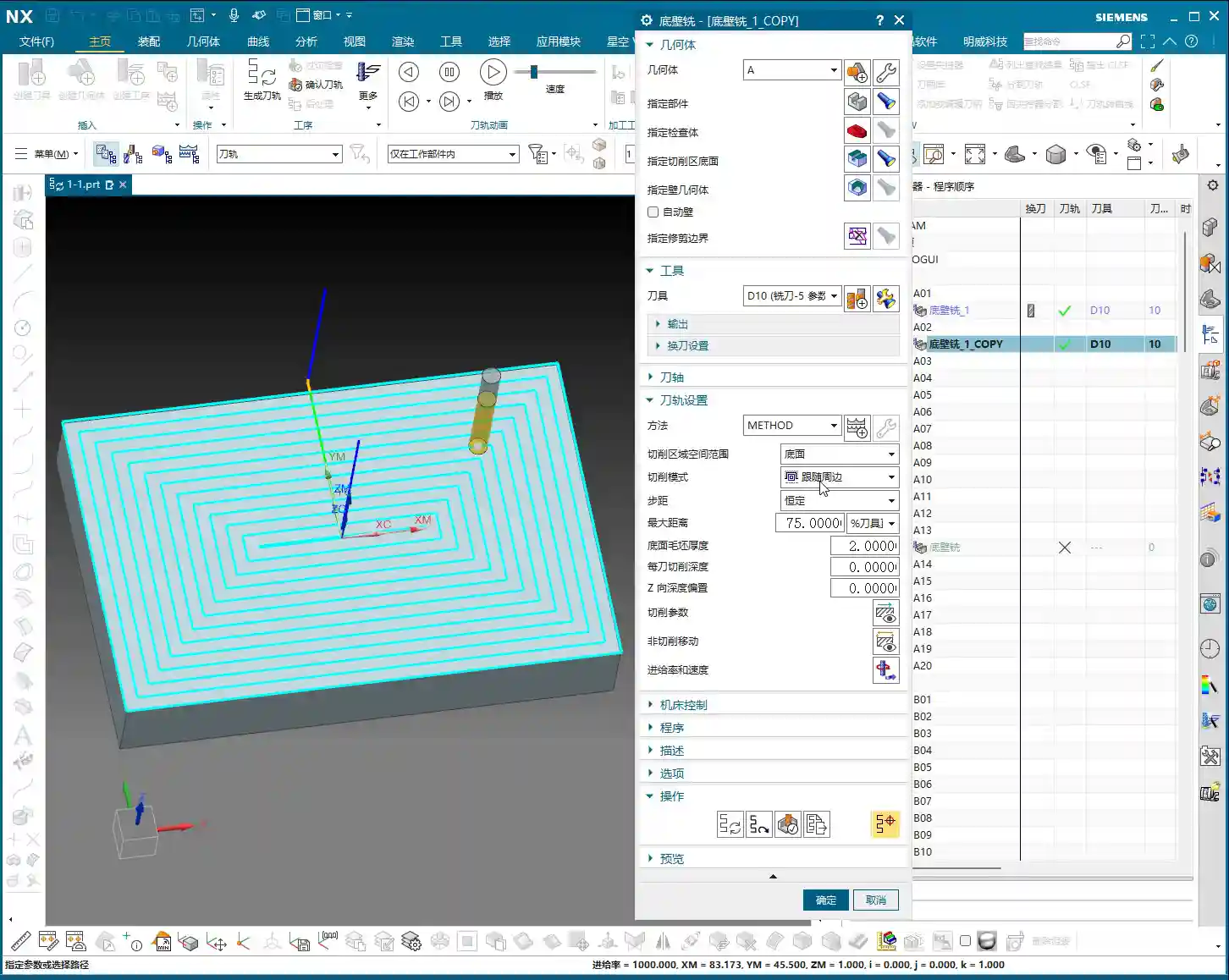
What does ‘Cutting Method’ mean? Simply put, it’s the way the toolpath moves. Let’s change it to ‘Follow Part’ and see if there’s any change. For our simple face milling, there’s actually no change.
However, if we change it to Contour, then there will definitely be a change. ‘Contour’ mode only machines contours. Since we are currently face milling, it’s not applicable, and it will give an error: ‘This component cannot perform face cutting on a planar surface’. So, face milling definitely cannot use ‘Contour’ mode.
One-Way Cutting
Let’s try One-Way. One-way is definitely possible. See? It engages the tool from this side, moves to that side, then lifts the tool and returns, then engages the tool from that side and moves back. This is a one-way machining method: move across, lift tool and return, move across again, lift tool and return again.
Zig-Zag Cutting
Since you understand one-way, Zig-Zag is even easier to grasp. It just moves across, then directly down, then across again, then down again. That is: move across, go down, return, then move across again, go down, return. It just keeps milling like that.
This, then, is our ‘Cutting Method’.
Summary: Pitfall Guide
Everyone must pay attention to the filter settings, especially when you’re first practicing; not being able to click toolpaths is often because the filter isn’t selected correctly. Furthermore, the tool axis usually doesn’t need to be changed in 3-axis machining, mainly focus on the +ZM axis. The choice of cutting method depends on the type of machining; for example, face milling usually selects ‘One-Way’ or ‘Zig-Zag’, while ‘Contour’ mode is not suitable for planar cutting. Understanding these will greatly improve your programming efficiency and machining stability.
Alright, we’ll finish this lesson here. We’ll continue in the next lesson. Thank you all for watching, goodbye!