📝 Key Takeaways: Master Wang personally teaches secret tips for NX programming of graphite undercut parts with complex geometries. Reveals why traditional surface drive methods fail, details how to cleverly use auxiliary surfaces to create “straight” projection toolpaths, ensuring perfectly orthogonal UV directions, and emphasizes the critical setting of projection vectors to “Toward Drive Geometry” to achieve efficient and precise machining, solving practical challenges not found in textbooks.
[VIDEO_HERE]
Hello everyone, I’m Old Wang, Master Wang. Today, let’s discuss **undercut machining** on complex graphite parts. This task might seem straightforward, but it’s full of potential issues. Especially when programming in NX, many get confused right from the start. Don’t worry, let me walk you through it. These are practical lessons I’ve learned over the years, not something you’ll find in textbooks.
I. Why Do Traditional “Surface Drive” Toolpaths Fail? —Avoiding the First Pitfall
When encountering undercuts, the common first reaction is to use **Surface Drive** or **Streamline Milling**. That’s not wrong, and it works most of the time. But when dealing with complex-shaped graphite parts like these, especially those with sloped surfaces and intricate undercuts, directly applying a Surface Drive toolpath is guaranteed to cause problems. Let me demonstrate directly so you can see clearly.
1. Directly Selecting Surface Drive: Error!
I select all the undercut faces on the part, try a Surface Drive toolpath, and immediately an error pops up: “Cannot create mesh.” Why? Don’t just look at the software interface; you need to consider the part’s geometry!

2. Root Cause Analysis: Asymmetrical Boundaries and Inconsistent UV Directions
This area is prone to errors. Surface Drive toolpaths require the boundaries of your selected drive surfaces to be **symmetrical and uniform**. Look closely: aren’t the boundary lines around the top and bottom of the undercut face different in number? The top might have six lines, while the bottom only has five. This directly prevents the software from establishing a clear reference for the toolpath. Furthermore, the UV directions of these two faces might be inconsistent; one could be twisted, while the other is relatively straight, making them incompatible.
**Listen up**, this is like pulling a rope: if the tension is uneven at both ends, the rope will surely tangle or even break. Machining operates on the same principle; if the data source is asymmetrical, it cannot generate a smooth toolpath for you. Therefore, using a Surface Drive toolpath directly, from NX’s perspective, is an unreasonable task. It gives you an error to prevent you from messing things up on the machine.
II. Master Wang’s Specialty: Cleverly Using “Surfaces” to Break the Impasse — A Change in Approach
Since direct surface drive isn’t working, we need to change our approach. Textbooks teach theory, but in practical operations, we need to be flexible. This technique is what I often call the **“Auxiliary Surface Projection” method**. Simply put, it involves first creating a flat “dummy surface” nearby, generating a smooth toolpath on this dummy surface, and then projecting this smooth toolpath onto our actual undercut face. Isn’t that like taking an indirect approach to success?

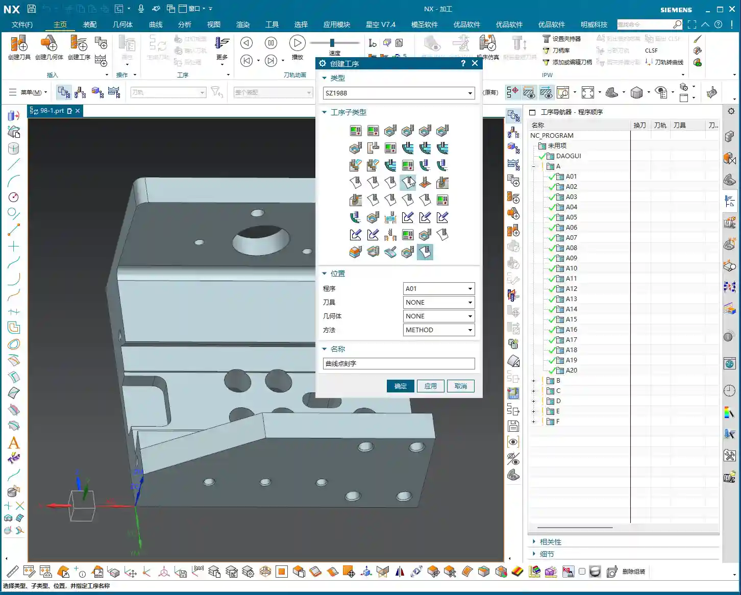
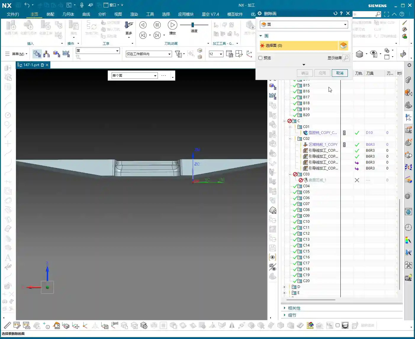
1. Creating “Upright Surfaces”: Establishing the Projection Reference
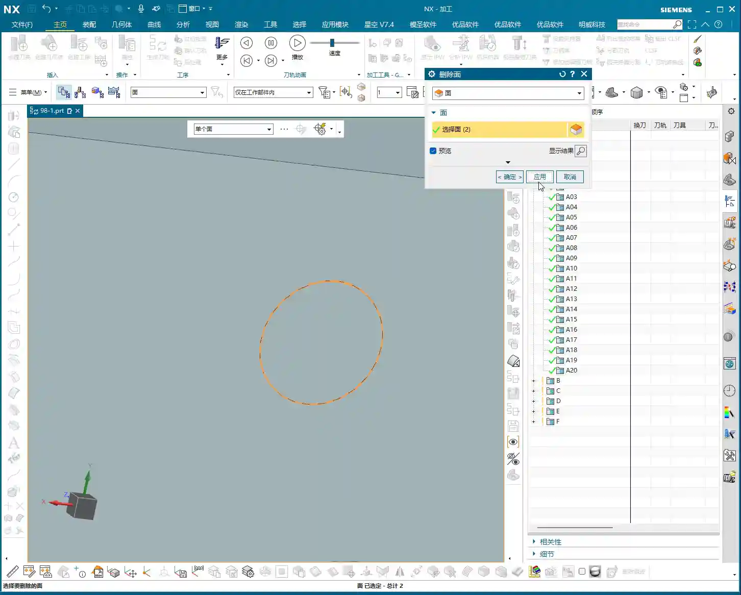
This is crucial. You need to copy the original part into a new layer, then delete all fillets and chamfers; we want a clean geometry. Next, on the outside of the part (remember, **outside**, not directly on the part’s edge), draw two vertical auxiliary lines. These two lines must completely cover the undercut area.
Then, use the “Extrude” command to extrude these two lines into two surfaces, effectively “slicing” the part. This way, you will get two **straight surfaces, perpendicular to the horizontal plane**. We want these “straight” surfaces, not skewed or twisted ones. Why? Because it ensures that the toolpath you generate afterwards will be smooth before projection, preventing it from wildly moving in and out, and leading to more stable cutting conditions.
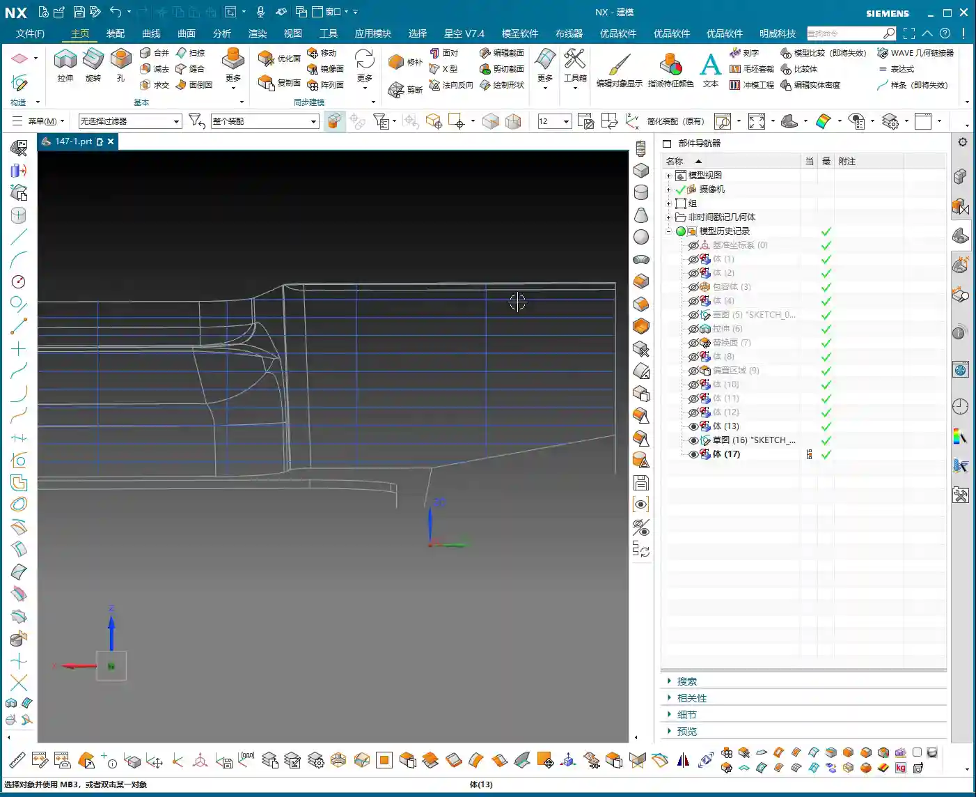
2. Critical Validation: Auxiliary Surface UV Directions Must Be “Orthogonal and Aligned”
Many people overlook this step, but it determines the success or failure of your toolpath projection. Drag out the auxiliary surface you just created a little, then check its **UV directions**. Remember, the UV directions must be **perfectly orthogonal**, like a neat grid paper. If it appears twisted or mesh-like, you need to adjust it. Only with orthogonal UV directions can you ensure that the projected toolpath won’t deform, preventing the “irregular machining marks” we often talk about, which affect surface finish and can easily cause tool wear.
III. Toolpath Generation and Projection — Key Considerations for 5-Axis Programming

1. Tool Selection and Initial Toolpath Generation
For undercuts, we typically choose a **Lollipop Mill**, for example, a **Φ12.5 mm** (approx. 0.49 inch) one. Its spherical end design effectively handles undercut areas and avoids interference. Select the “upright surface” you just created as the drive surface and generate the toolpath. The initial toolpath will definitely have some issues, and the direction might be off, but don’t panic.
You need to manually **specify the direction**, instructing the tool to cut from the bottom of the undercut upwards, or adjust it according to your desired cutting direction. This is like shaving; you have to go with the grain, or it hurts. It’s the same for machining; a proper feed direction reduces cutting forces, protecting both the tool and the workpiece.
Additionally, setting the **retract height** to **0.2 mm** (approx. 0.008 inch) is crucial. Too high wastes time with excessive air cuts; too low risks tool collisions or even recutting, leading to surface damage. Graphite is a brittle material, so controlling the retract height effectively prevents chipping.
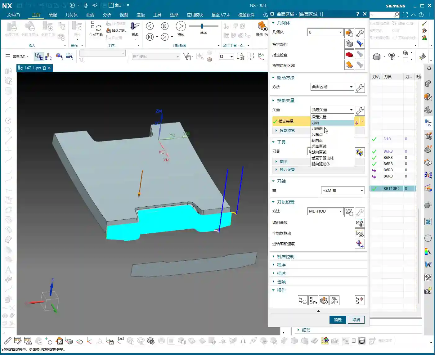
2. Core Technique: Toolpath Projection, Vector Settings Are Key!
The initial toolpath is ready; now for the main event — **Toolpath Projection**. In the projection options, you need to project the toolpath onto the undercut face of our original part.
Here’s a **huge pitfall** that many fall into: the **Projection Vector** setting! Absolutely DO NOT select “Tool Axis” or “Specify Vector”; you MUST select **“Toward Drive Geometry”**!
Why? “Toward Drive Geometry” means that the toolpath will be projected perpendicularly onto the actual part surface, following the direction of the “auxiliary surface” you previously created. This ensures that the toolpath is copied completely and accurately, preventing deformation or missed cuts due to improper projection direction. If you select “Tool Axis,” the tool might project along its own axis, distorting the toolpath and ruining your machined undercut!
As for parameters like “Retract Distance,” the default setting is fine; you don’t need to worry about it.
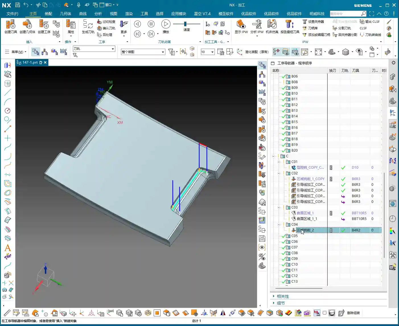
IV. Detail Refinement and Rest Material Removal

1. Supplementary Machining for Other Areas
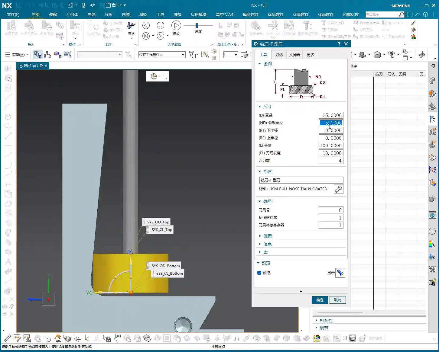
For 2.5D areas or very small corner radii, you might need to use a smaller ball end mill. Last time I wanted to find a B4 ball end mill, but it wasn’t in the default NX library, so I had to define it myself. These are common occurrences; always select the appropriate tool and path based on the actual situation.
Overall, toolpath programming is a comprehensive task; you can’t rigidly stick to just one command. Only by thinking critically, experimenting, and combining knowledge of material properties with actual machine conditions can you truly hone your skills.
Summary: Pitfall Avoidance Guide
- Pitfall One: Directly using “Surface Drive” for complex undercut geometries often fails due to asymmetrical boundaries or inconsistent UV directions.
- Pitfall Two: When creating auxiliary surfaces, failing to ensure their “perfectly orthogonal” UV directions leads to distorted toolpath projection.
- Pitfall Three: During toolpath projection, incorrectly selecting “Tool Axis” or “Specify Vector” instead of **“Toward Drive Geometry”**, resulting in toolpath deformation or incomplete machining.
- Pitfall Four: Unreasonable retract height settings, affecting machining efficiency and surface quality.
- Master Wang’s Secret: When encountering complex surfaces, boldly use auxiliary geometries (surfaces, dummy bodies) as transitions to simplify the complex. Modeling and programming are not a one-step process but rather about **“building bridges and paving roads”**.
👤 About the Author:
The author is a veteran CNC machining professional with 15 years of industry experience, specializing in UG NX programming. This article is an original work representing personal practical insights.
⚠️ Copyright Notice: Unauthorized reproduction or distribution without prior communication is strictly prohibited.