📝 Key Takeaways:
NX Floor-Wall Milling: Practical Roughing of Through-Holes with “No Bottom Face”
Hello everyone, I’m Master Wang. Today, we’re going…
Hello everyone, I’m Master Wang. Today, we’re going to discuss the NX Floor-Wall Milling function, especially how to cleverly handle through-holes that have “no bottom face.” This is practical experience you won’t find in textbooks, so pay close attention—there’s a lesson in every detail!
Preparation is Key: Program Post-processing
For us in manufacturing, once a program is created, the first step is to generate the NC code. Don’t underestimate post-processing; there are many intricacies involved.

Efficiency Secret: Batch Post-processing
In Siemens NX, you can select a single operation and directly click the A04 Post-process button. However, if you have many operations, post-processing them one by one is too slow. Listen up: you can select all operations (or select the folder containing them), then directly click “Batch Post-process” in the post-processing menu. This generates NC code for all operations at once, saving time and effort—it’s a neat trick for boosting efficiency. As for the file format, whether it’s NC or MDF (e.g., for Siemens controllers), that depends on your machine and company standards; just make sure to select the correct one.
Traditional Solution for “No Bottom Face” Through-Holes: Modeling to Create a Virtual Face

Alright, back to today’s main topic. Floor-Wall Milling, as the name suggests, requires a bottom face. However, in real-world machining, you often encounter through-holes that are just smooth cavities—where’s the bottom face for you to select?
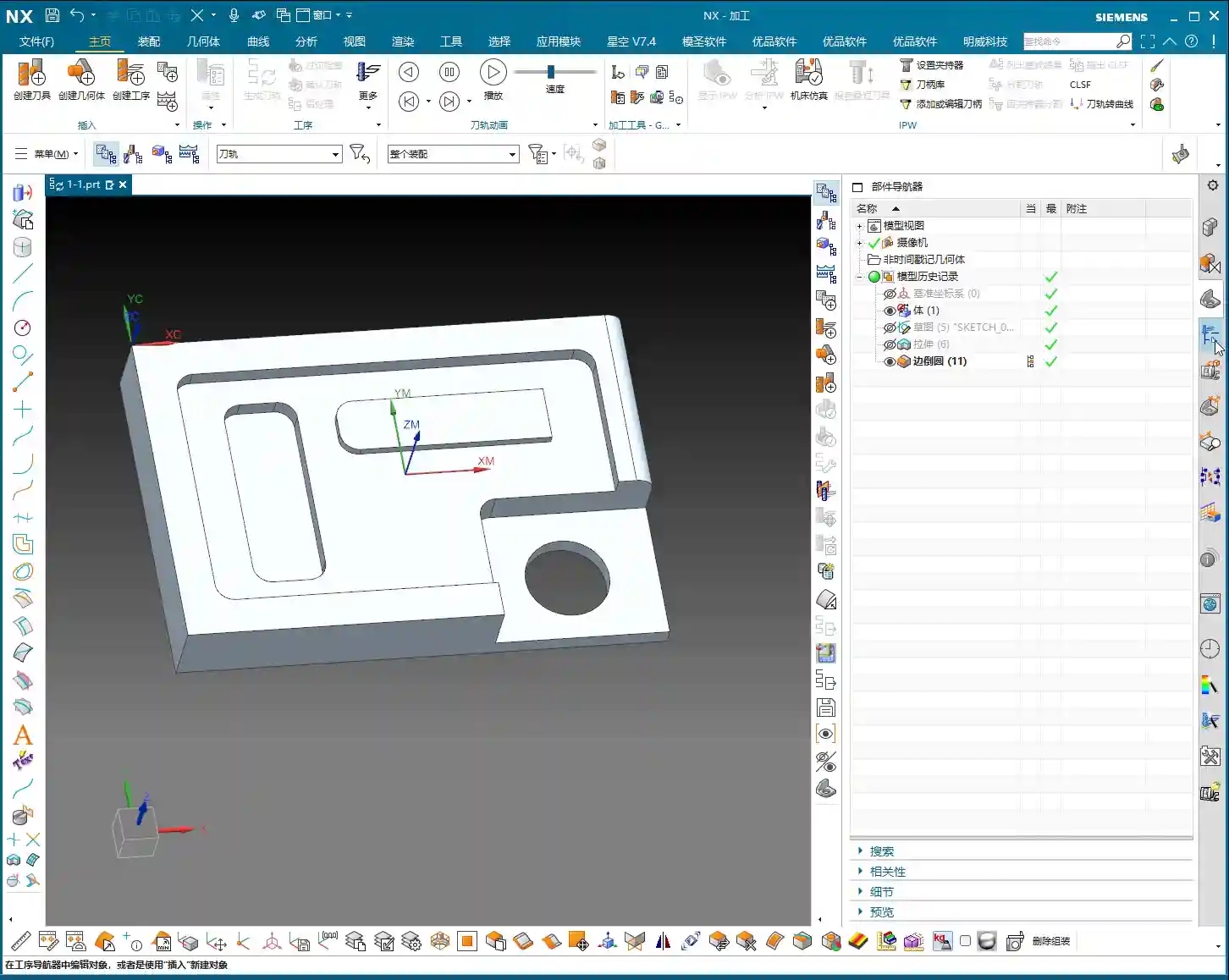
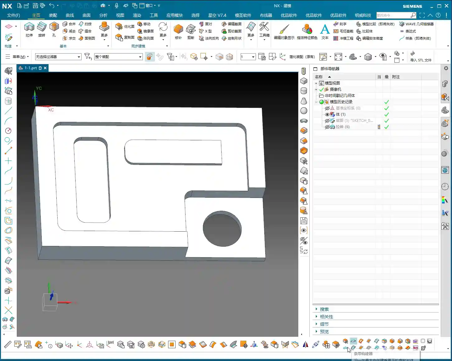
Creating a Bounded Plane: A Virtual Bottom Face
The most straightforward method is to “trick” the software by creating a bottom face for it. In the Modeling module, find the “Bounded Plane” function. By selecting the edge curves of the through-hole, you can generate a temporary sheet body, which we’ll use as our “bottom face.” Once this temporary bottom face is created, your machining operation will have a reference.
Floor-Wall Milling Operation Settings: Pay Attention to the Filter
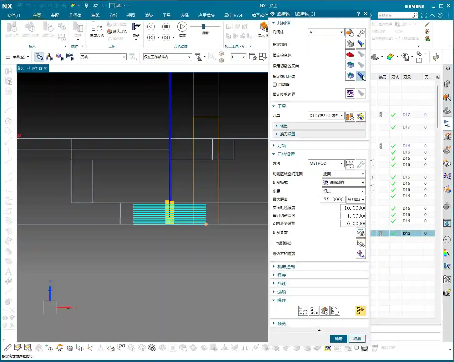
After creating this virtual bottom face, we can proceed to create a Floor-Wall Milling operation as usual. When selecting the machining area, pay attention to one detail: the filter for “Specify Part” might default to “Sheet Body.” If you’re selecting a solid body, it won’t be recognized. In this case, you need to change it to “No Selection”, then select your entire part for machining. Don’t forget this detail, or the software will throw an error.

Then, for specifying the bottom face of the cut area, select the Bounded Plane we just created. For the remaining parameters, such as the Depth of Cut (DOC), when roughing, I generally prefer to set it a bit larger (e.g., 1 mm). This increases machining efficiency; don’t just think about tool life, but also overall cost and lead time.
The “Red Face” Warning for Geometry Changes: Don’t Mess with References

Listen up: In NX, if your operation suddenly turns red, it usually means your original geometry or referenced objects have been modified or deleted. For instance, if you add a fillet to the part in Modeling, or delete a sheet body referenced by the operation, the machining operation will immediately show a “red face.”

A “red face” means the operation is invalid and requires re-specifying the geometry or re-generating the toolpath. Therefore, once a machining operation is created, try not to modify or delete the original modeling geometry, especially any areas referenced by the operation. If you absolutely must make changes, be prepared to update the operation accordingly.
When a Bottom Face Truly Doesn’t Exist: Roughing by Specifying “Walls”
So, what if I don’t want to create a Bounded Plane in Modeling, or I simply want to rough directly using “walls”? Of course, there’s a way! However, personally, Master Wang doesn’t use this method very often.
Master Wang’s Practical Choice: Planar Milling is More Efficient
When I do machining, I prioritize efficiency and stability. For roughing such through-holes, if there’s truly no bottom face to reference, I generally opt for “Planar Milling”. It provides more direct toolpaths for planar contours and through-holes, and its parameter settings align better with my workflow. I typically use Floor-Wall Milling for situations where there’s a bottom face and side walls need finishing. However, since we’re discussing it today, I’ll explain clearly how to select these “walls.”

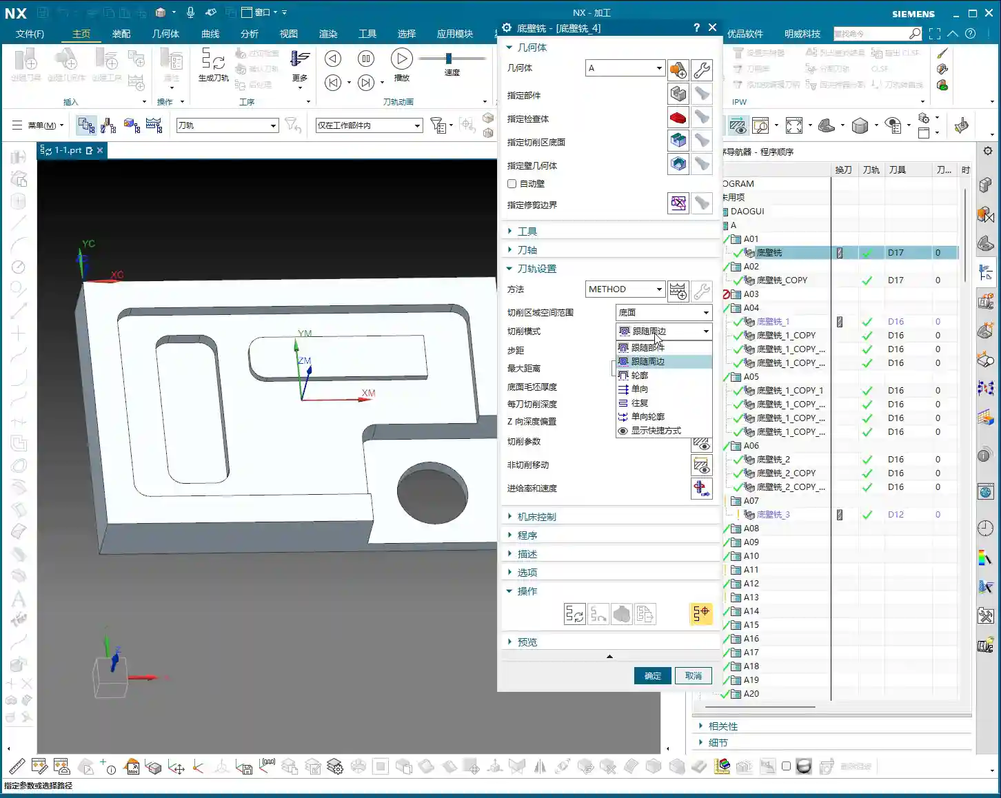
Practical Demonstration of “Specify Wall”: Appears Similar, but There’s a Difference
When creating a Floor-Wall Milling operation, if you cannot specify a bottom face, you can select “Specify Wall” instead. At this point, you’ll need to select the inner wall faces of the through-hole. Then, generate the toolpath, and you’ll notice it looks identical to the toolpath generated when specifying a bottom face. It also cuts layer by layer according to the defined Depth of Cut (DOC) (e.g., 1 mm per pass for a total depth of 10 mm).

Pitfall: Stock Allowance Setting Trap
However, there’s a crucial pitfall here, pay close attention! When you choose “Specify Wall” for machining, the default “Part Stock” is ineffective! Any stock allowance you set there will not be recognized by the operation. Where is the actually effective stock allowance? It’s hidden under the “Walls” option, specifically in “Wall Stock”!
If you use “Specify Wall” for roughing and want to leave stock on the side walls, you must set it in “Wall Stock.” This differs from our usual habit of setting a unified stock allowance in “Part Stock.” Many users stumble here, resulting in the operation finishing the side walls with no stock left—milling straight to the final dimension! That’s why I don’t use this method often; it’s too prone to errors, requiring constant vigilance.
The “Z-Depth Offset” Secret for Depth Control
Additionally, among the cutting parameters for Floor-Wall Milling, there’s a parameter called “Z-Depth Offset.” This parameter is particularly useful in certain specific situations.
Its purpose is to allow the tool to cut a bit more or a bit less in the Z-direction. For example, if you want to machine a hole completely through, but the model’s Z-depth is exact, you can input a positive value here, such as “1”, and the tool will cut an extra 1 mm deeper, ensuring the hole breaks through completely. Conversely, inputting a negative value will result in less material being cut. This function is simple and practical, helping you solve many minor depth control issues.

Summary of Floor-Wall Milling Functions and Cross-Operation Parameter Reuse
Overall, the Floor-Wall Milling operation is very powerful and capable of many tasks:
- Surface Finishing: Performing a finishing pass on plane surfaces.
- Roughing: Typically by selecting a bottom face and using a “Level Periphery” cutting pattern for rough machining.
- Bottom Face Finishing: Performing a finishing pass on the bottom plane.
- Side Wall Finishing: Performing a finishing pass on side walls, with the option to leave individual stock allowances.
While “Specify Wall” for roughing is an option, considering stability and error prevention, Master Wang personally rarely uses it for roughing. I more highly recommend creating a Bounded Plane in Modeling, or directly switching to a “Planar Milling” operation to handle through-holes without a bottom face.
After discussing Floor-Wall Milling for so long, you’ll find that many parameters in NX machining operations are interconnected. For instance, “Cutting Pattern,” “Stepover,” “Cutting Parameters,” and “Non-Cutting Moves,” among others. Their names, functions, and locations are largely similar. Therefore, by mastering one operation, you can quickly get the hang of many others—this is the principle of “understanding one, understanding all.” In future discussions about other operations, I won’t dwell on these repetitive parameters; you can apply what you’ve learned and understand them by analogy.
Summary: Pitfall Avoidance Guide
- Batch Post-processing: When you have many operations, make good use of the batch function to generate all NC code at once, boosting efficiency.
- Specify Part Filter: When selecting a part for machining, if it’s not recognized, check if the filter is set to “No Selection.”
- Protecting Original Geometry: Once machining operations are created, try not to modify or delete the original modeling geometry referenced by the operations, otherwise, the operations will turn “red” and become invalid.
- “Specify Wall” Stock Allowance Trap: When using Floor-Wall Milling and selecting “Walls” for machining, remember that “Part Stock” is ineffective! All side wall stock allowance must be set in “Wall Stock.” This is the most common place for errors, so be extremely careful.
- Preferred Method for Through-Holes: For roughing through-holes without a bottom face, Master Wang personally recommends creating a “Bounded Plane” in Modeling as a virtual bottom face, or directly using a “Planar Milling” operation, to ensure stability and efficiency.
- Z-Depth Offset: When fine-tuning machining depth, make judicious use of the “Z-Depth Offset” parameter, especially when machining through-holes.
Alright, that concludes today’s practical experience sharing. In NX programming, attention to detail determines success or failure. These “textbook-untaught” tips require practice and thoughtful application to truly become your own hard-earned skills! See you next time!
“`
👤 About the Author:
The author is a veteran CNC machining professional with 15 years of industry experience, specializing in UG NX programming. This article is an original work representing personal practical insights.
⚠️ Copyright Notice: Unauthorized reproduction or distribution without prior communication is strictly prohibited.