📝 Key Takeaways: Master Wang dives deep into UG NX 1980’s ‘More’ and ‘Connection’ functions, explaining practical techniques for setting safe distances, detecting tool collisions, and optimizing cutting paths and rapid moves. Eliminate unproductive air cuts, boost machining efficiency, and tackle common production challenges head-on!
Hello everyone, I’m Master Wang. Today, let’s continue to delve into those practical tips in UG NX 1980 that you won’t find in textbooks.
“More”: The Secrets of Tool Holders and Collision Detection
Listen up, this ‘Check Tool and Clamping Device’ feature is very useful. You need to understand that only when the system knows the shape and dimensions of your tool holder can it help you perform collision checks. If you haven’t created the tool holder, the system is flying blind and can’t check anything.
So, to make good use of this function, the first step is to create the tool holder. Generally, we can set up the tool holder at the same time as we define the clamping device.
How to Set Tool Holder Parameters
Additionally, you can find the clamping device settings under ‘Tool’s’ ‘Edit Display’. As long as you know the tool holder parameters, you can set them here. This part is relatively simple; you can figure it out yourselves with a bit of exploration.
Typically, Siemens NX’s (formerly UG NX) simulation software itself comes with some tool holder settings, but for those of us doing practical work, we need to have a clear understanding.
The Practical Meaning of Safe Distance
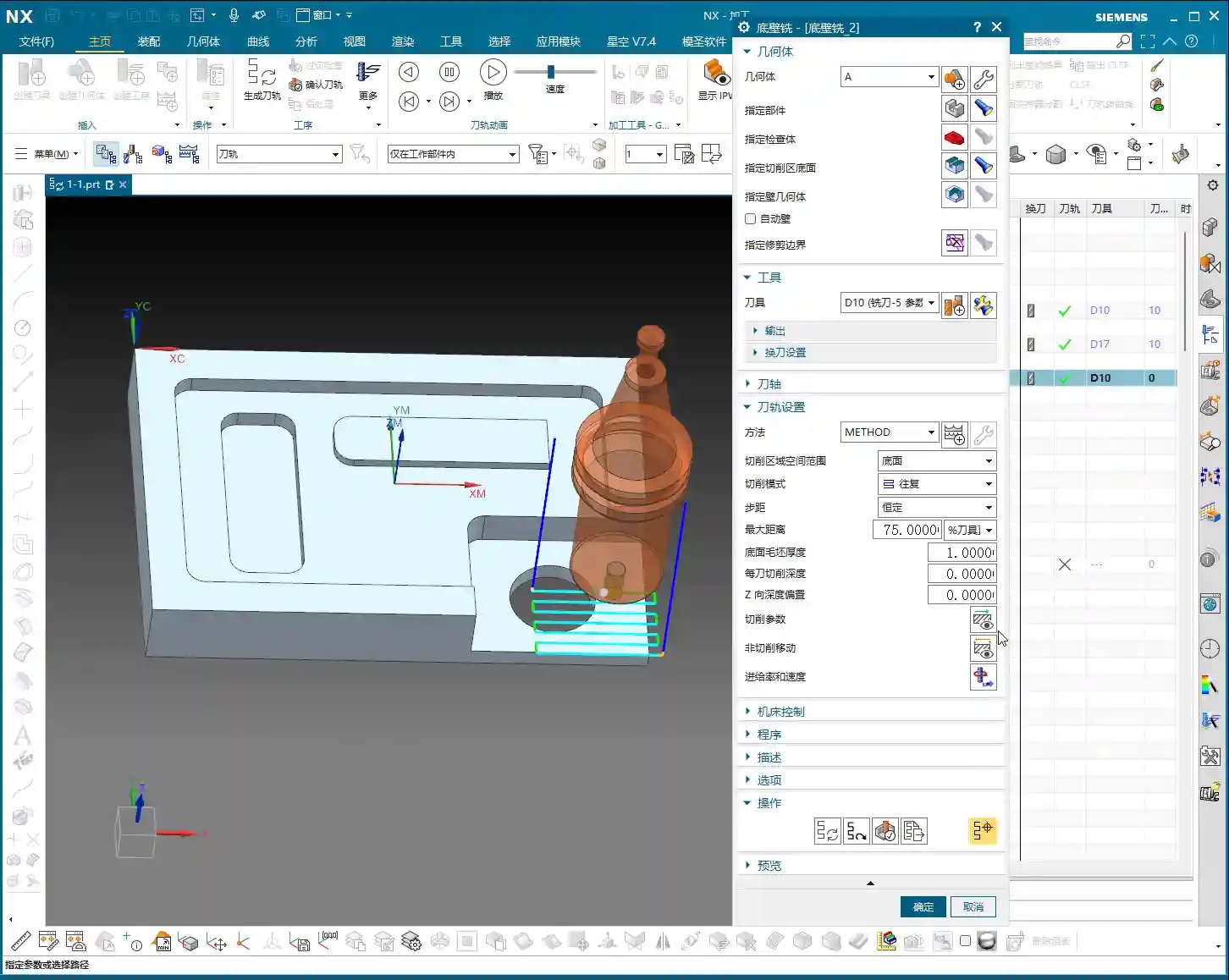
Alright, let’s reopen it now. In the ‘Operation Navigator’, the spatial range has pretty much been covered. Let’s look inside ‘More’, there’s a parameter for ‘Clamping Device’.
See it? The default is 3mm. This small arrow points to the safe distance from the edge of the tool holder to the workpiece. This means that the closest point of our tool holder to the workpiece must maintain a minimum clearance of 3mm. This is to prevent the tool holder from colliding with the workpiece during machining, which could lead to accidents or scrapped parts.
Let’s change it, for example, input 10mm. Isn’t it obviously much larger? From here to here, it now maintains a safe distance of 10mm. Master Wang reminds you, this distance is critical for safety!
The Nuances of Collision Check and Pitfall Avoidance
You all now understand the meaning of ‘More’ here; it’s about providing a safe distance for the tool holder. If ‘Collision Check’ is not ticked, no matter what number you enter here, the system will ignore it! Because you haven’t activated the collision detection function, it won’t read your set safe distance. It’s like telling someone you’re afraid of heights, and then going skydiving – who’s to blame then?
So, for this safe distance to take effect, you must tick that ‘Collision Check’ box! Otherwise, no matter how many numbers you input, it will treat you as air. These are lessons learned the hard way; don’t make such basic mistakes.
Usually, when programming 3-axis toolpaths, we don’t need these functions because the tool holder is generally far from the workpiece. But for 5-axis or complex cavity machining, you really need to make good use of them.
“Connection”: Optimizing Toolpaths, Boosting Efficiency
Having finished ‘More’, let’s talk about ‘Connection’. This function directly relates to your machining efficiency and machine tool lifespan, so listen closely!
First, let’s change the tool. Earlier, we used a 10mm diameter tool and set its tool holder. Now, if we switch to a 12mm diameter tool, you’ll find the tool holder is gone. Why? Because we only set the clamping device for the 10mm tool; the 12mm tool hasn’t been set yet. NX isn’t that smart; not all tools share one clamping device setting.
We’ll now demonstrate using a ‘Face Milling’ (光底壁) machining method. This is a very common machining strategy.
Region Sorting: Optimize vs. Standard
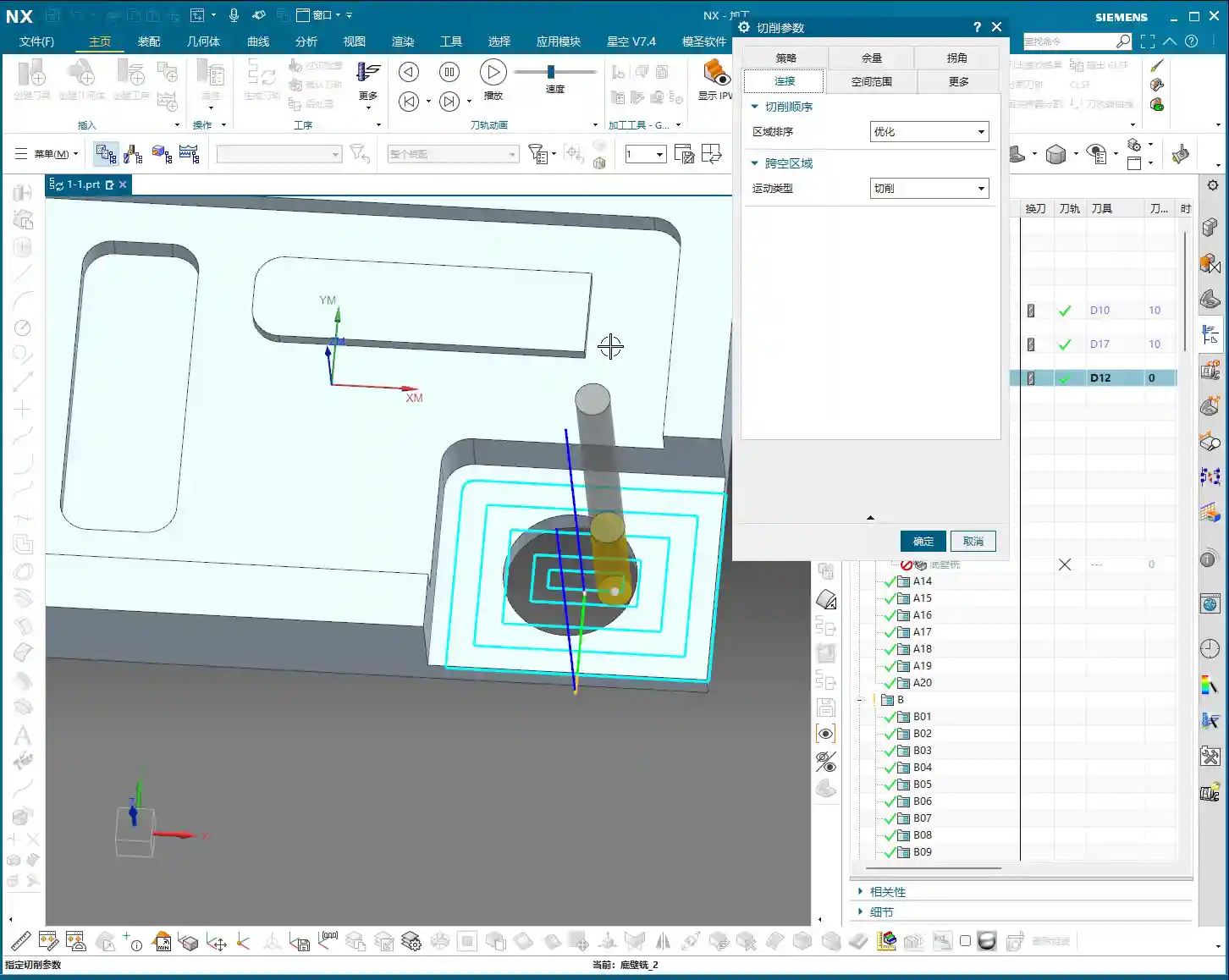
Let’s look at the ‘Region Sorting’ option under ‘Connection’. There are two types: ‘Optimize’ and ‘Standard’.
For example, if we’re machining several regions. If you choose ‘Optimize’, the system will automatically plan the most efficient path for you. It won’t rigidly follow a sequence, but rather, based on the actual situation, it will choose the closest, smoothest route. For instance, it might machine this region first, then that one, then jump to another – all calculated by the computer. This greatly reduces air cut time, and saving money is making money!
If you choose ‘Standard’, it’s not as intelligent. It might machine this first, then run to a distant one, then jump back, darting all over the place. This will create many unnecessary air cuts, wasting time and increasing machine wear, which is not worth it. So, Master Wang tells you, in general, just choose ‘Optimize’, don’t mess around with those infrequently used options.
Cross-Empty-Space Motion Type: Cut, Follow, Move Tool
Next is ‘Cross-Empty-Space Motion Type’, which includes ‘Cut’, ‘Follow’, and ‘Move Tool’.
In ‘Cut’ mode, if there are voids or discontinuities in the middle of the machining area, the toolpath will go straight through, as if it didn’t see them. This might leave some paths in the air, but for some simple shapes, it’s also a method.
Let’s switch to a new operation to demonstrate, otherwise, changing too many parameters can lead to problems.
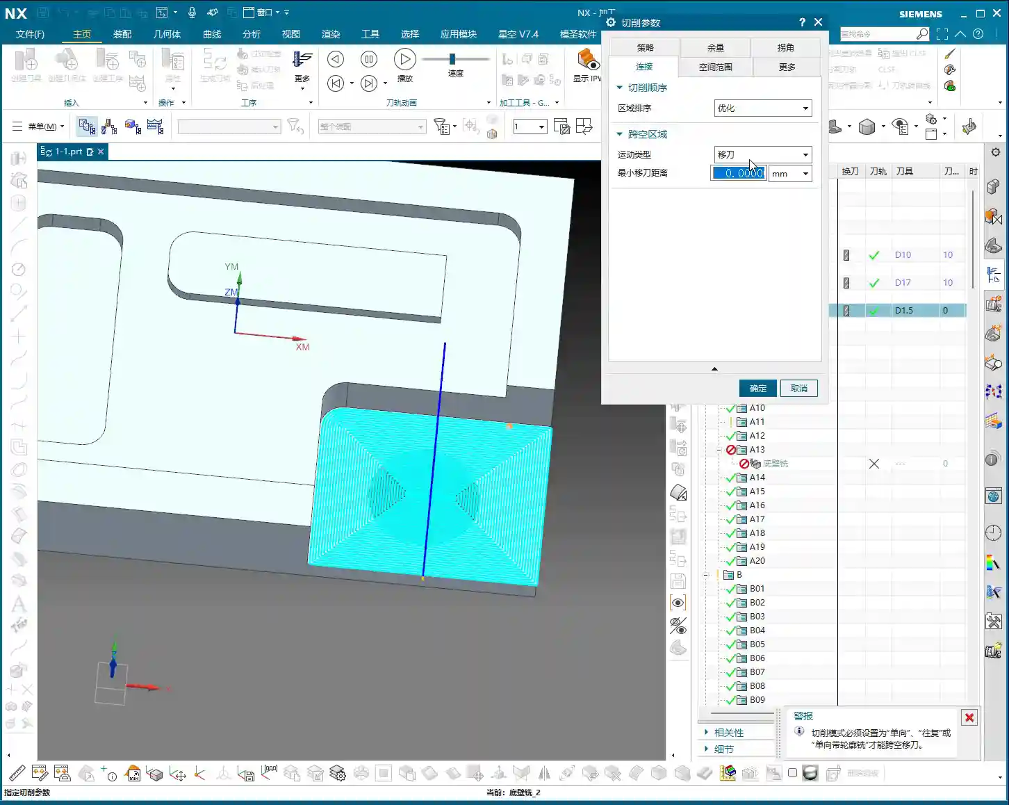
Okay, now let’s select a bottom face and use a smaller tool, like a D3. Then, change ‘Cut’ to ‘Follow’ and generate it.
It’s clear now, isn’t it? In ‘Follow’ mode, the tool will stick close to the boundary, instead of cutting straight through like ‘Cut’. This avoids tool movement in areas that shouldn’t be machined, saving some time.
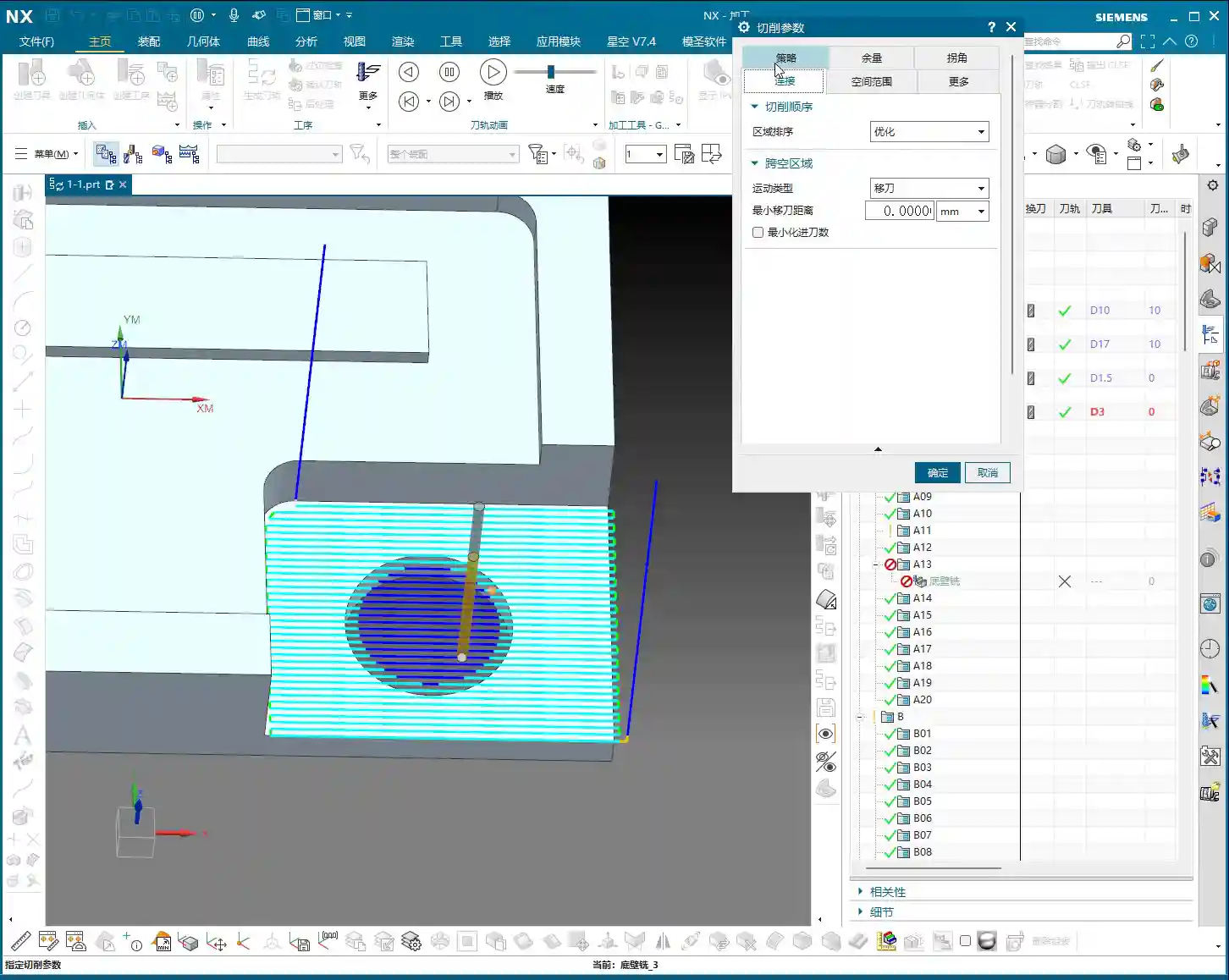
Let’s try ‘Move Tool’. ‘Move Tool’ means that when the tool moves from one cutting region to another non-connected cutting region, it will lift up and travel in a rapid move (G00), with a blue line indicating this intermediate section. See this blue line? It means rapid move. This can greatly shorten the idle travel time. For example, it moves to this position, finishes cutting, and needs to go to another position; it will lift the tool and rapid move there directly, very quickly. Only when it reaches the new cutting point does it resume normal cutting speed. This can save a lot of machining time, especially for complex parts.
So, ‘Cut’, ‘Follow’, and ‘Move Tool’ are all quite commonly used, just choose flexibly according to the actual situation.
Finishing Pass Toolpath: ‘Beautifying’ the Workpiece
Finally, let’s look at the ‘Add Finishing Pass Toolpath’ function.
For example, after machining a region, if you want its edges to be smoother and dimensions more accurate, you can use this. It will add an extra pass along the already machined path, which is equivalent to a ‘finish cut’ (光刀), to clean up the remaining material on the surface. It’s like ‘beautifying’ the workpiece.
Here you can also set the ‘Number of Passes’. For instance, if you want to make a few passes along the edge, just input that number. It might be used less often normally, but it can be very useful at critical moments.
Summary: Pitfall Guide
- Tool Holder Setup: Safe distance settings are only effective if the tool holder is created and ‘Collision Check’ is ticked. Otherwise, whatever you input is useless. This is the most easily overlooked point!
- Region Sorting: In most cases, prioritize ‘Optimize’. It helps you automatically plan the most efficient toolpath, reducing air cuts and saving time and effort.
- Cross-Empty-Space Motion Type:
- Move Tool: Suitable for non-cutting regions with longer distances, allowing for rapid tool lifts (G00), greatly improving efficiency.
- Follow: Suitable for machining along boundaries or specific shapes, resulting in a more precise path.
- Cut: Can also be used in some simple, continuous regions, but be aware of potential unproductive air cuts.
- Finishing Pass Toolpath: If you have extremely high requirements for surface quality and dimensional accuracy, you can use the ‘Add Finishing Pass Toolpath’ function for additional finish cuts along the edges. However, make sure there’s actually material to cut, don’t just cut air.
- Practicality First: No matter how good software simulation looks, ultimately it’s about the cutting sparks on the machine and the part’s accuracy. Get hands-on, observe more, and you’ll become a true master!
Leave a Reply