📝 Key Takeaways:
UG Planar Milling “Specify Part Boundaries”: A Practical In-depth Guide
Introduction: The First Step in Machining, Boundaries Determine Success
Listen up, everyone! I’m Old Wang, Master Wang. I’ve been grinding in the machining industry for fifteen years, from the shop floor to the programming desk, handling more parts than you’ve eaten rice. Today we’re talking about “Specify Part Boundaries” in Planar Milling. It sounds simple, but it’s the most fundamental and error-prone aspect of Siemens NX programming, especially for planar milling. Don’t underestimate it: incorrect boundary selection can lead to unnecessary air cuts and wasted time, or worse, scrapped parts, and even damaged tooling and machines! This is no joke; it’s real hard-earned money we’re talking about.
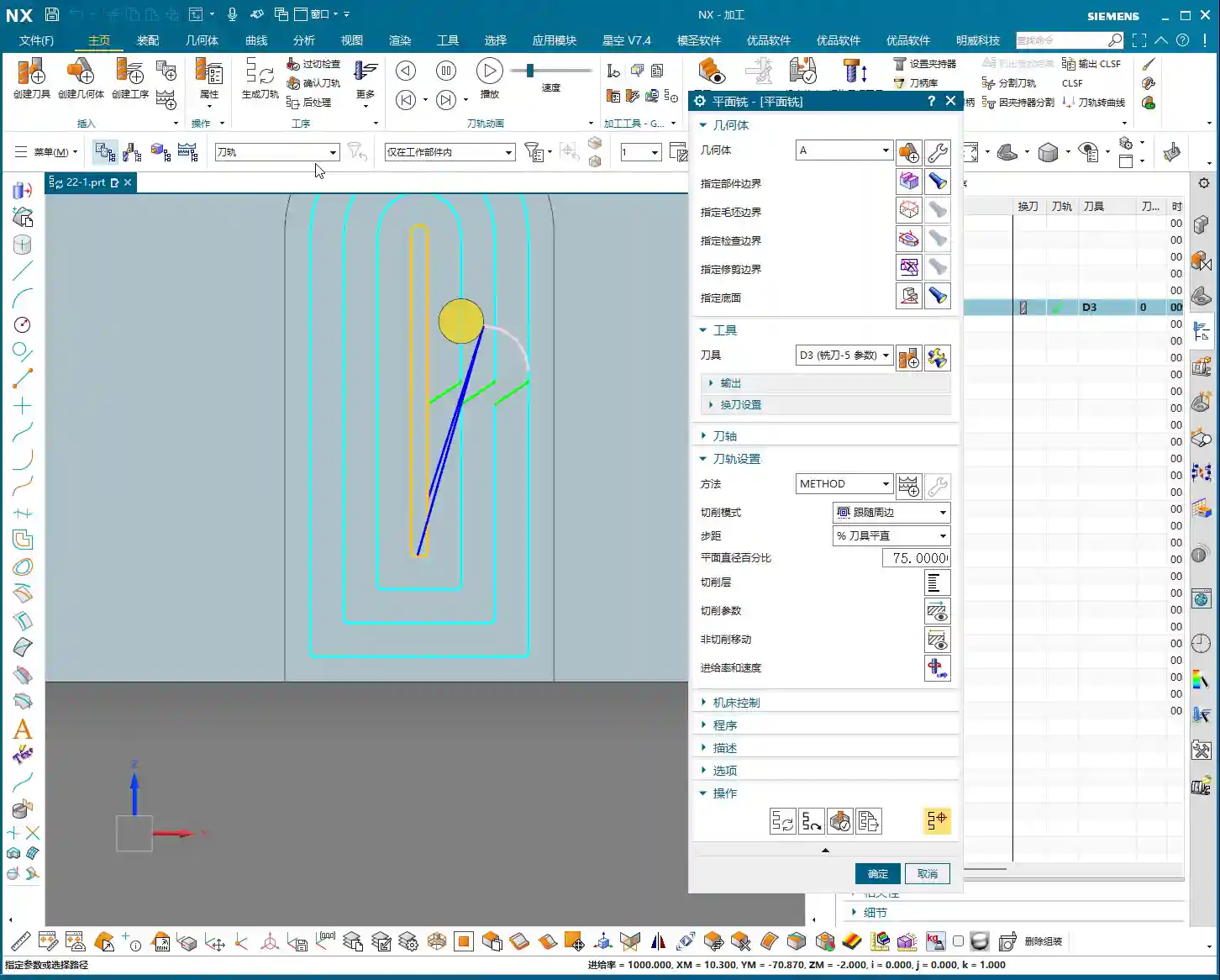
Siemens NX Planar Milling, as the name suggests, generates 2D toolpaths, primarily for machining flat surfaces or steps. Its core principle is to mill downwards, layer by layer, along a boundary you define. So, you absolutely must define this “boundary” clearly.
Core Function of Siemens NX Planar Milling’s “Specify Part Boundaries”
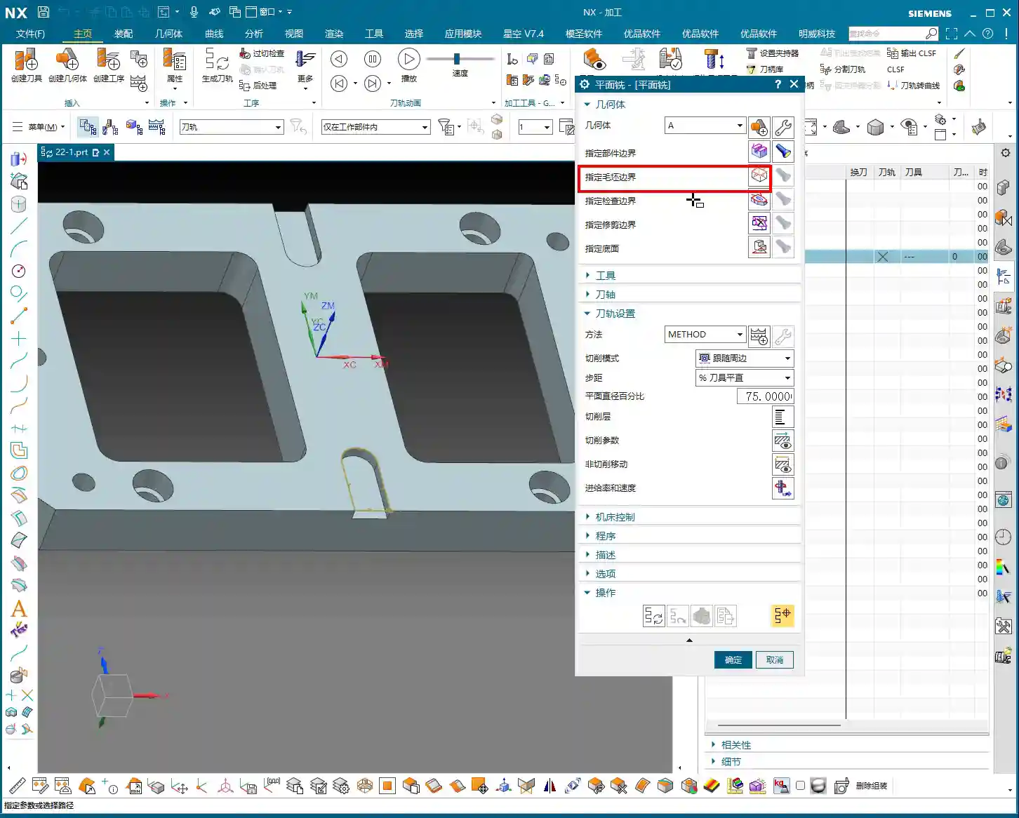
What are “Part Boundaries”?
Simply put, “Part Boundaries” tell the machine and the cutting tool, “You can only work within this area; stop once you cross this line!” It defines the tool’s horizontal machining limits. For any part we machine, we need a specific machining area. How do we define this? By specifying part boundaries. If chosen correctly, the toolpath will precisely follow the part’s contour; if chosen incorrectly, you’re in for trouble.
Boundary Selection: Faces vs. Curves, Which is Better?
In Siemens NX, there are typically two methods for specifying part boundaries: selecting “Faces” or selecting “Curves”.
The Pitfalls of Face Boundaries
Beginners might find selecting “Faces” convenient; you just click, and the entire face highlights. But I, Master Wang, advise you: try to avoid using “Faces” to specify boundaries, especially for complex parts! Why? Because a face might contain many unnecessary feature lines, or some face edges might not be clean, leading the software to automatically generate a boundary that isn’t what you intended. For example, if you only want to machine the contour of a block, but the face also has some small holes, selecting the face might cause the software to include the boundaries of these holes. The tool could then make unnecessary air cuts, or even worse, machine areas it shouldn’t. In actual production, this means wasted time and reduced efficiency.

The Advantages of Curve Boundaries
Selecting “Curves”, on the other hand, is what I, Master Wang, recommend most, and it’s the most commonly used method in production. Even if your part has no solid body, only a wireframe, you can still perform planar milling. The benefits of choosing curves are:
- Precise Control: You select exactly which boundary line you want; it’s crystal clear and leaves no room for ambiguity.
- Flexibility: Even if a feature’s face on the part is irregular, as long as the curve is accurate, we can still machine it.
- Avoid Misoperation: Significantly reduces machining issues caused by incorrect automatic software detection.
When selecting curves, functions like “Tangent Curves” can be used to quickly select continuous boundary lines, saving time and effort.
Key Parameter Settings: Inside/Outside, Top Face, and Bottom Face
Selecting the correct boundaries isn’t enough; there are several core parameters that directly determine whether your toolpath will effectively cut material.
Tool Inside/Outside: Avoiding the Minefield of Overcutting and Undercutting
After selecting the boundary lines, you must tell Siemens NX whether the tool should machine on the “Inside” or “Outside” of that line.
* If your machining goal is to clear material from an internal cavity (e.g., milling a pocket or groove), then the tool must machine on the inside of the boundary line. If you select the outside, the tool will just wander around the exterior, leaving the inside untouched – that’s underrunning (undercutting), a wasted effort!
* If your machining goal is to mill the external contour of a part, then the tool must machine on the outside of the boundary line. Conversely, if you select the inside, the tool will cut directly into the interior of your part – that’s overcutting, and the part is instantly scrapped!
Don’t just rely on software simulations; look for the cutting sparks! On an actual machine, selecting the wrong inside/outside can truly be “one cut ruins everything.” This is where the tool is most likely to crash/overload and produce scrap, so you must keep a sharp eye on it.
Top Face and Bottom Face: Defining Machining Depth and Range
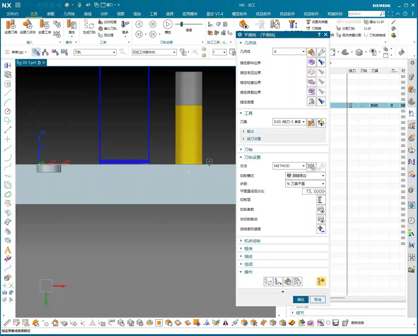
* Top Face: This defines the highest Z-axis plane where the tool begins machining. You must clearly tell the software at what height the tool should start its cut. If the top face is set too high, the tool will just rapid in the air, wasting time (air cuts); if set too low, it might directly collide with unmachined material, causing a tool crash.
* Bottom Face: This defines the lowest Z-axis plane where the tool stops machining. It determines your machining depth. If the bottom face is set too shallow, material won’t be machined completely (undercutting); if set too deep, you might mill through the part or hit the fixture, which is another huge problem.

Together, these precisely define the tool’s machining range in the Z-axis direction. You must specify them; do not rely on the software’s automatic detection, especially for complex or high-precision parts. Manual specification is essential to ensure foolproof operations.
Considerations for Additional Boundaries: Check and Trim
Beyond the core part boundaries, top face, and bottom face, Siemens NX also offers more advanced boundary control options.
Specify Check Boundaries: Practical Techniques for Fixture Avoidance
This “Specify Check Boundaries” function is similar to the “Check Geometry” we usually use, but here, it can only select lines. What’s its main purpose? It’s used to prevent the tool from colliding with fixtures or areas of the part that you don’t want to touch.
For instance, if you have a part clamped with a strap clamp and you don’t want the tool to approach it, you can select the clamp’s outline as a check boundary. The tool will automatically avoid this boundary during machining. This is a crucial method for ensuring machining safety, preventing tool crashes, and reducing scrap. Remember, only lines can be selected here; don’t try to click solid faces.
Specify Trim Boundaries: Controlling the Machining Area
“Trim Boundaries” are used to further limit the machining area. For example, if you’ve selected a large face as a part boundary but only want to machine a small area on that face, you can use trim boundaries (such as point trimming or rectangular trimming) to confine the toolpath to that small area. This function is extremely useful in certain localized finishing pass or repair machining operations, preventing the tool from taking unnecessary paths and improving efficiency.

Optimizing the Process: Multi-Area Machining and “Add New Group”
The Clever Use of “Automatic Detection”
When specifying the bottom face, you might encounter a problem: you want the tool to mill straight through to the part’s bottom, or to the bottom of a specific feature. In such cases, simply selecting a single face might not be sufficient. I, Master Wang, recommend that when you need to machine to a certain depth, especially for “through-machining,” you try switching “Specify Area” to “Automatic Detection”, and then select your desired bottom face. This allows the software to perform a more intelligent analysis of your selected face, ensuring the toolpath reaches your desired depth and avoids undercutting. It’s a great way to improve efficiency and robustness, saving you unnecessary detours.
“Add New Group”: Key to Boosting Efficiency
Sometimes, a part has multiple distinct areas that require planar milling, and these might not be on the same level or could have varying shapes. Are you going to create a new operation for each individual area? That would be incredibly inefficient!
Siemens NX has a very practical function called “Add New Group.” You’ll find this button in the “Specify Part Boundaries” interface. Its purpose is to allow you to define multiple independent machining boundaries, top faces, and bottom faces within a single operation.
For example, if a part has two separate grooves that need milling, you can define the boundaries, top face, and bottom face for the first groove in the first group; then click “Add New Group” and define the parameters for the second groove. This way, a single operation can generate toolpaths covering multiple areas, significantly reducing programming time and making subsequent program management much cleaner. This is one of the “secret weapons” for boosting efficiency in practical applications.
Planar Milling Characteristics: It Only Recognizes Lines, Not Overcutting!
Finally, I, Master Wang, must emphasize another point—a practical experience rarely taught in textbooks: the planar milling operation is very “rigid.” It only recognizes the boundary lines you specify; even if you’ve selected “allow overcutting,” it will not actively machine beyond that line. It won’t extend the toolpath to achieve a final shape like some other strategies. Therefore, if you want to cut slightly outside the boundary line, you’ll need to manually offset that boundary line outward a small amount. This point is crucial; many beginners stumble here, getting incorrect part dimensions and blaming the software. The software isn’t the problem; you just haven’t fully understood its “temperament”!

Summary: A Guide to Avoiding Pitfalls
Everything we’ve discussed today is a summary of my (Master Wang’s) years of experience; every word is solid gold. Remember these points to save yourself a lot of unnecessary hassle:
1. Prioritize selecting “Curves” as part boundaries. This provides precision and control, avoiding interference from unnecessary features.
2. Be extremely cautious when selecting inside/outside. This is a critical step that determines the fate of your part; selecting incorrectly leads directly to scrap.
3. Top and bottom faces must be specified. Strictly control the Z-axis machining range to prevent air cuts, overcutting, and undercutting.
4. “Specify Check Boundaries” only recognizes lines. Use it for fixture avoidance and to ensure machining safety.
5. Make good use of “Automatic Detection” to define bottom faces. It’s more reliable, especially for through-machining.
6. Master the “Add New Group” function. This enables one-time programming for multiple areas, boosting efficiency and reducing setup.
7. Understand planar milling’s characteristic of “only recognizing lines.” If you need to machine beyond the boundary, manually offset the curve.
Once you’ve mastered these points, you’ll truly be able to leverage Siemens NX’s planar milling, creating high-quality, high-efficiency toolpaths and producing parts that satisfy customers. This isn’t just about technical skill; it’s the foundation for our products to succeed in the market!
👤 About the Author:
The author is a veteran CNC machining professional with 15 years of industry experience, specializing in UG NX programming. This article is an original work representing personal practical insights.
⚠️ Copyright Notice: Unauthorized reproduction or distribution without prior communication is strictly prohibited.
Leave a Reply