📝 Key Takeaways: Master Wang shares the practical essence of full-sequence front-side programming for 24 parts on one plate in Siemens NX. He details tool selection for B6 ball end mills and D10 tools, from secondary roughing to finish milling and then to corner cleanup, analyzing stock allowance and spatial range settings. Special emphasis is placed on the helical upward and alternating outside-in corner cleanup strategy, solving complex toolpath issues, preventing software freezes, and significantly boosting machining efficiency and part accuracy. **
[VIDEO_HERE]
Hello everyone, I’m Master Wang. Today, let’s dive into the intricacies of “full-sequence front-side programming for 24 parts on one plate” in Siemens NX. On the surface, this task might seem like simple multi-part replication, but to execute it cleanly and efficiently—saving significant time and effort—there’s a real art to it. Especially with full-sequence front-side machining, from roughing to finishing and then to corner cleanup, you can’t rush any step. So listen closely, I’m going to lay out some practical, real-world techniques that textbooks often overlook.
Step One: Secondary Roughing, Laying the Foundation
We’ve already completed the preceding operations. Now, let’s move directly into the secondary roughing phase. The goal of secondary roughing is to quickly remove excess material, leaving a uniform stock allowance for subsequent finishing passes. If this step isn’t executed properly, the finishing pass can easily experience heavy tool engagement, or even result in scrapped parts.

Tool Selection and Machining Area
First, insert the tool, and we’ll select the secondary roughing operation. The machining objects are, of course, all the parts; make sure to select every single one. For this specific area, we’re going to use a B6 ball end mill for the initial roughing. The benefit of a ball end mill lies in its spherical tip; during surface milling, it helps maintain relatively stable cutting conditions and minimizes step formation.
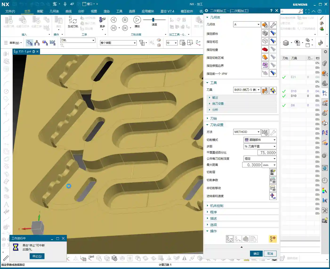
Depth Control and Stock Allowance Settings
When machining, you need to keep a close eye on the bottom surface. Otherwise, it will undoubtedly cut too deep, consuming the stock allowance we painstakingly preserved. When reaching the final layer, we typically leave a 0.2 mm stock allowance. This allowance provides enough material for the finishing pass without excessively burdening the roughing operation. I later checked and found that adjusting the allowance to 0.3 mm was also perfectly sufficient.
For the spatial range, we can set it to 5. As for the reference tool, use a D10 tool; this allows for a more accurate calculation of residual material. Remember to add a small approach distance to prevent the tool from directly impacting the workpiece, thereby protecting both the tool and the spindle.

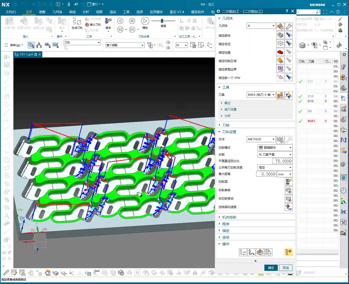
Calculation Time and Coping Strategies
Generating toolpaths? This is where things can easily go sideways. Especially with multiple parts and complex surface milling, the software can calculate at a painfully slow pace! Just now, my machine took several minutes to process a single secondary roughing program; I almost thought it had crashed. In such situations, don’t just sit there waiting! If you’re following a course, you can simply skip this segment. In actual production, however, you either optimize parameters, calculate by region, or if all else fails, you simply need patience. Or, as I later considered, calculate a portion first, then mirror it over—that can save a significant amount of time.
Step Two: Finishing Pass, Pursuing Precision and Surface Finish

Once the foundation from roughing is properly laid, the next stage is the finishing pass. The finishing pass directly determines the part’s final dimensional accuracy and surface finish. This step demands stability: toolpaths must be smooth, and cutting parameters must be meticulously set.
Finishing Area Selection and Tool Application
Likewise, insert the tool and select the finishing pass function. First, select all the surfaces requiring a finish cut. Here, we’ll still use a B6 ball end mill. Start by selecting just two or three surfaces to generate the toolpath and check the results. If everything looks good, then select all remaining surfaces and generate the toolpath in one go. Don’t rush to select everything at once; if even one surface has an issue, you’ll have to recalculate everything, which is a waste of time.
That slow secondary roughing calculation earlier really got under my skin. Now, this finishing pass program calculates significantly faster, which tells us that our chosen machining method and parameters are indeed appropriate.

Step Three: Corner Cleanup, Removing Residual Material
Residual Material Analysis and Tool Selection
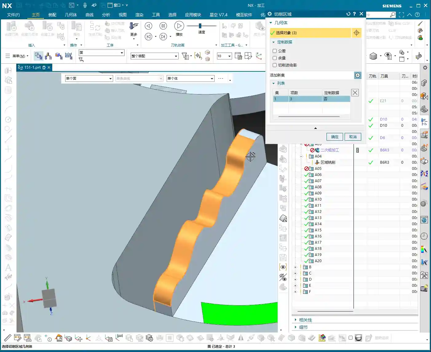
After the finishing pass, inspect the results. If you find that certain areas are still a little off, it’s highly likely that corner cleanup is necessary. We’ll select smaller tools, such as a B3 or B2.1 ball end mill for the corner cleanup. Remember, the tool for corner cleanup must be smaller than the tools previously used to reach into the finer corners.
For the target surface of corner cleanup, simply select the exact surface that needs to be cleaned. We won’t set a stock allowance here, as the objective is to clean it completely.
CRITICAL! Toolpath Strategy Optimization: Helical Upward and Outside-In
The corner cleanup toolpath strategy—this is a major pitfall! The method I initially used still left residual material, and that toolpath approach was genuinely problematic, leading to heavy tool engagement. In this situation, you absolutely cannot go from inside-out or plunge directly. We need a different approach: use a helical upward motion, and make sure it alternates from outside-in. Also, remember to enable smooth transitions.
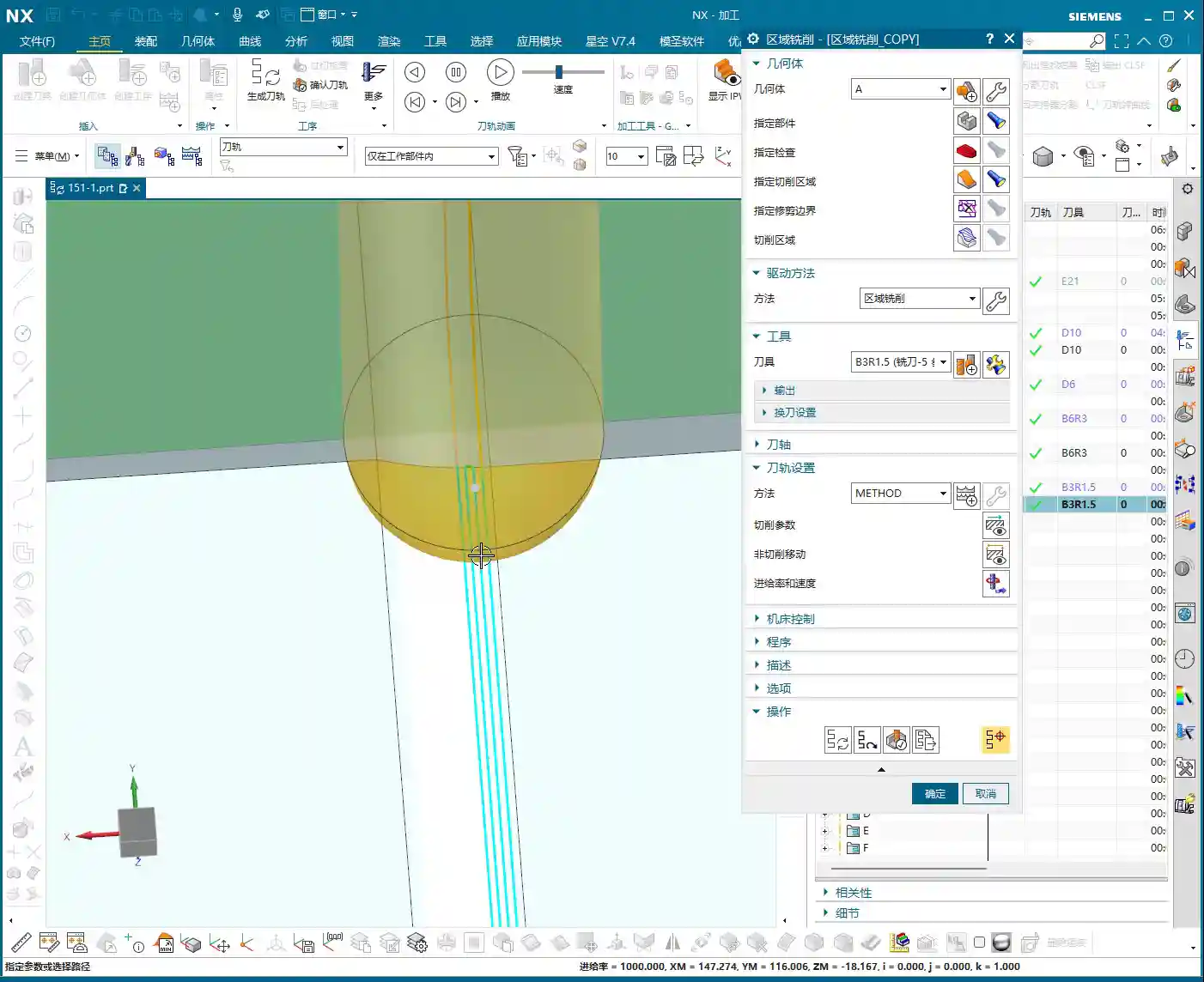
Why this approach? Because as you move from outside-in, the tool’s cutting load gradually increases. Before entering the core area of the workpiece, the tool has sufficient space for chip evacuation and heat dissipation. Furthermore, outside-in cutting prevents the tool from plunging directly into the material, which causes instantaneous impact and reduces the risk of tool breakage. This strategy is what truly protects the tool and enhances machining stability. The stepover can be set to a smaller value, such as 1000, to ensure thorough corner cleanup.
See? Once generated this way, isn’t the toolpath much better? Moving from outside-in, how could the tool possibly chip? It’s virtually impossible. This is the kind of practical experience you only get from real-world work.
Summary: Pitfall Avoidance Guide
- NX Programming: Long Calculation Times Are a Major Drawback: When dealing with complex multi-part programs, especially for roughing, extended calculation times are the norm. Don’t just sit there waiting! Consider calculating by region, mirroring, or setting the program to calculate overnight. Time is money; having a machine sit idle waiting for your program to calculate is literally burning cash.
- Stock Allowance Control Must Be Precise: The stock allowance left by secondary roughing for the finishing pass should be neither excessive nor insufficient. Too much increases the burden on finishing, while too little can lead to heavy tool engagement and chatter. 0.2-0.3 mm is a relatively safe empirical value, but it ultimately depends on the material and tool.
- Corner Cleanup Toolpath is Critical: Never underestimate corner cleanup! Especially in corners and deep cavities, an irrational toolpath—for instance, plunging directly down or moving from inside-out—can easily lead to tool chipping or breakage. Remember, helical upward and alternating outside-in—these are indispensable strategies for tool longevity!
- Don’t Just Rely on Software Simulation; Observe the Cutting Process: No matter how realistic software simulation is, it’s still a virtual representation. When running on the actual machine, you must observe the cutting sound, sparks, and chips. If the cutting sound is dull, sparks are white, or chip color looks abnormal, those are precursors to problems—stop the machine immediately and adjust!
- Tool Selection Must Match Material Characteristics: Different materials (aluminum, titanium alloys, nickel-based superalloys) have stringent requirements for tool material, coating, and geometry. Don’t expect one tool to do everything. Targeted selection will yield optimal results and prevent accuracy deviations caused by premature tool wear.
- Be Aware of Machine Tool Accuracy Errors: For parts with high precision requirements (±0.005 mm level), you cannot rely entirely on programming. You must understand your machine’s actual accuracy and compensation mechanisms. Only by adjusting the process and fine-tuning tool offsets can you truly meet drawing specifications.
👤 About the Author:
The author is a veteran CNC machining professional with 15 years of industry experience, specializing in UG NX programming. This article is an original work representing personal practical insights.
⚠️ Copyright Notice: Unauthorized reproduction or distribution without prior communication is strictly prohibited.
Leave a Reply