Tag: Backside Machining

  • Master Wang’s Real-World Guide: Backside Machining for Multi-Operation Parts – Siemens NX Programmin

    📝 Key Takeaways:

    Backside Programming for Multi-Operation Parts: Master Wang’s Practical Playbook

    I. Finishing the “Front Side”: Toolpath Optimization & Real-World Fine-Tuning

    Listen up, lads. We’ve finished the roughing; now it’s time for finishing. Don’t think finishing is just clicking around – there’s a lot to it, and you need to pay close attention to toolpaths and allowances.

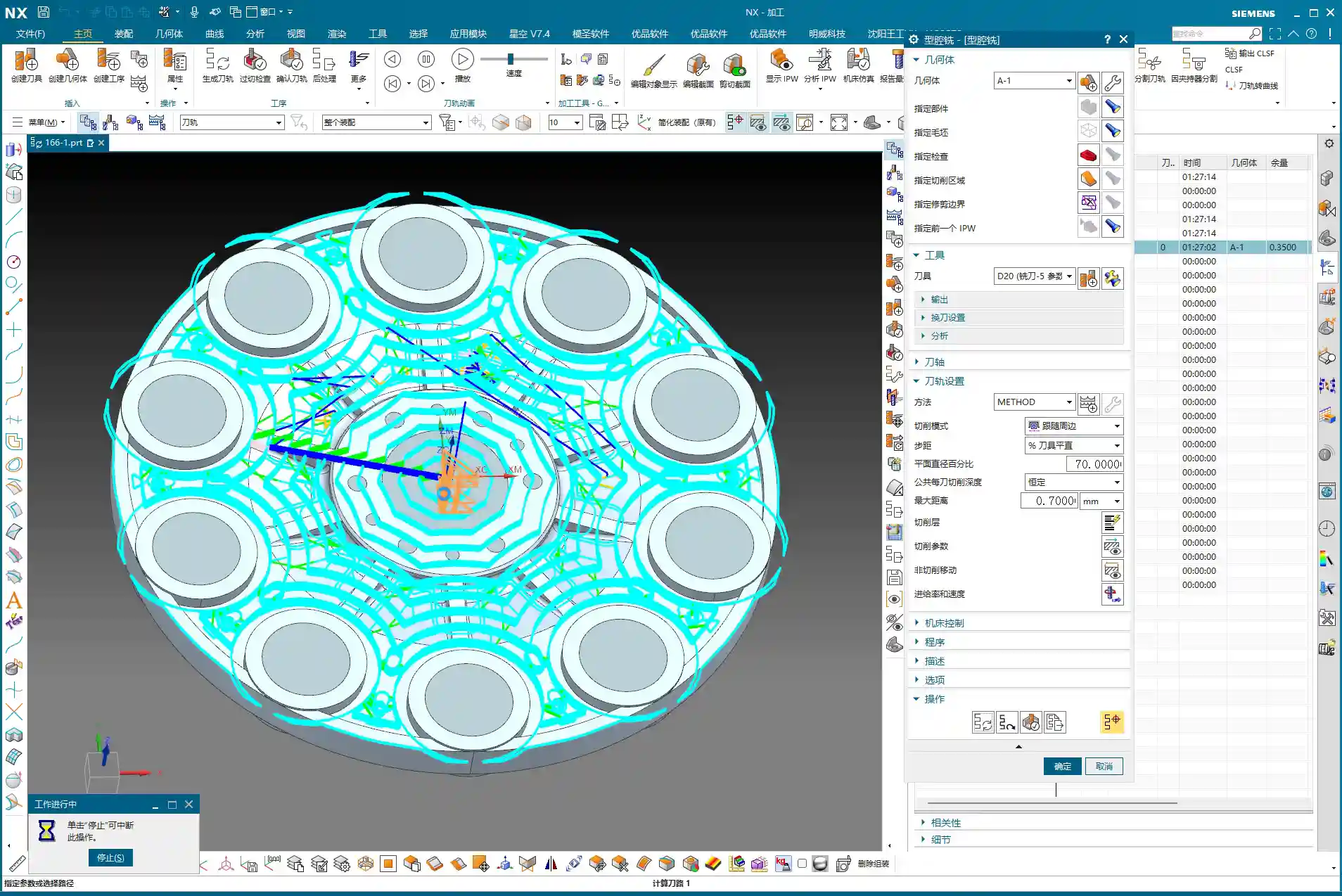
    1. Initial Finishing Strategy & Tool Reuse

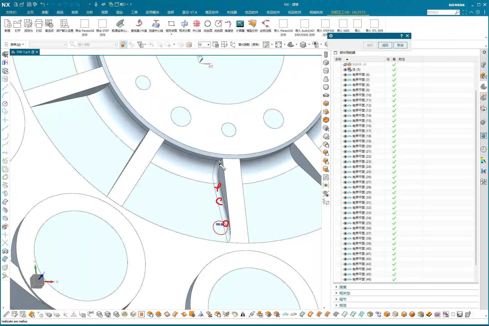
    For finishing, first off, you need to select the correct machining area, which is our “Specify Part” feature. This operation isn’t difficult, but many subsequent optimizations depend on the range you’ve selected. As for the tool, if your previous semi-finishing tool can handle it and the size is right, just reuse it. Saves tool change time, which boosts efficiency. Remember: economize wherever possible, but never at the expense of quality and safety.

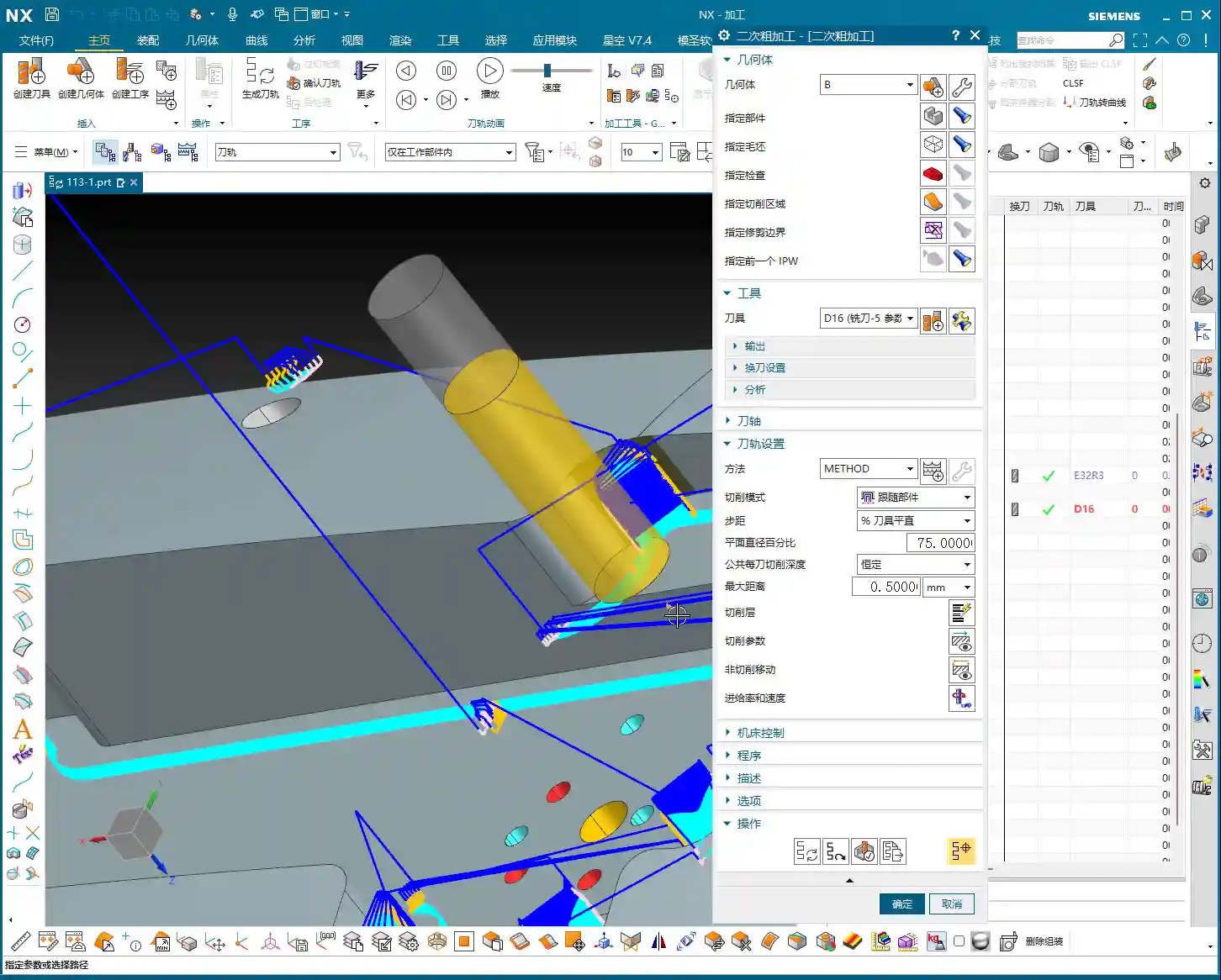
    2. Stepover Adjustment: “Deep Cuts, Shallow Steps” for Aluminum Finishing

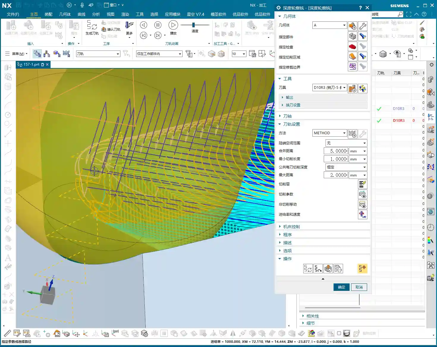
    When you first generate the toolpath, doesn’t the Stepover seem a bit large? Especially with aluminum parts – they’re soft, and chips tend to pile up during cutting. For finishing aluminum, we often ‘go deeper,’ meaning we can afford a slightly larger cutting depth, but each lateral step (Stepover) needs careful control.

    Looking at this first layer of toolpaths, the Stepover feels a bit too large. We can adjust it. For example, if the system default is 14.something millimeters, let’s manually change it to 13 mm. This makes the toolpath denser, which is crucial for achieving a better surface finish. For less critical areas at the top, the Stepover can be a bit more relaxed, say 2 mm; but for areas requiring a high-quality finish, set the Stepover to 0.15 mm – gotta strive for perfection, right?

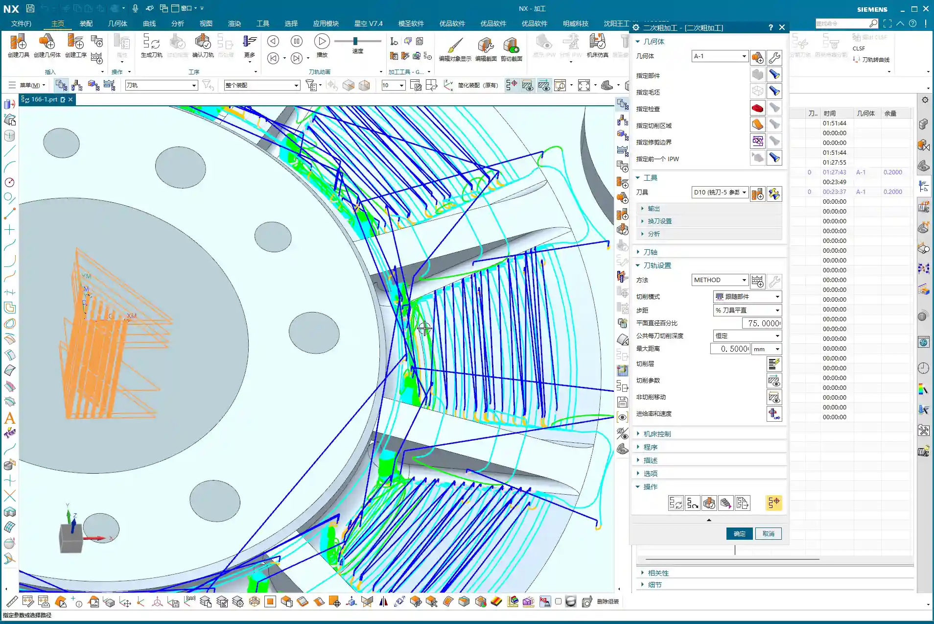
    3. Unnecessary Retracts & Practical Trade-offs

    After generating the toolpath, keen eyes might spot some “unnecessary retracts” – that’s when the tool makes excessive lifts and engagements in the air. This impacts efficiency and can even leave surface marks. In theory, we want to avoid these as much as possible, but my years of experience tell me that if there aren’t many, and they don’t significantly affect overall machining time or surface quality, we can “prioritize the bigger issues” and leave them for now.

    If these unnecessary retracts are indeed problematic, then we have to change things. For instance, try changing the cutting method to “Climb Milling”. Sometimes, this can effectively reduce those unwanted lifts and make the toolpath smoother. Don’t just rely on software simulations; look at the cutting sparks and the actual cutting sound – those are your most reliable indicators.

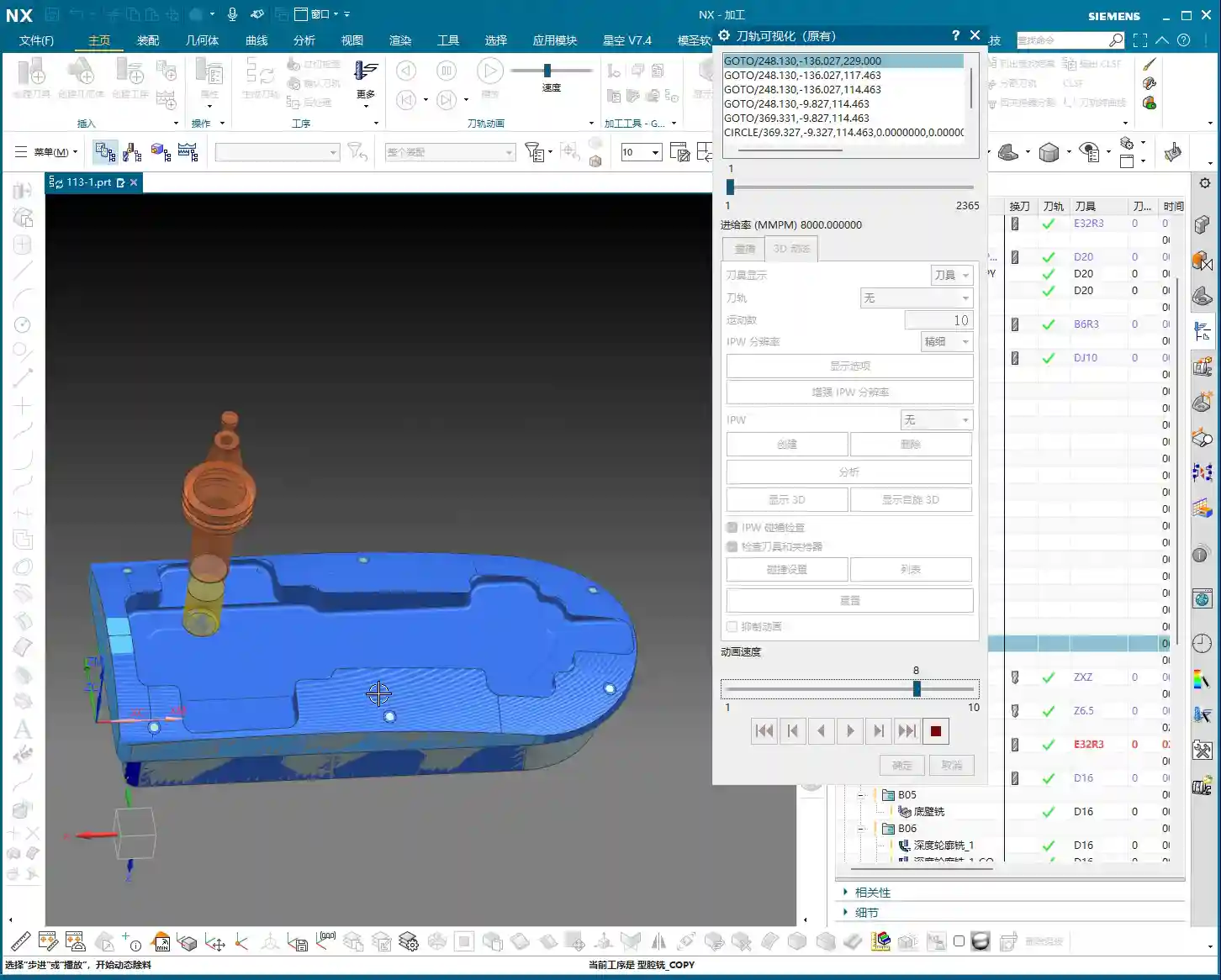
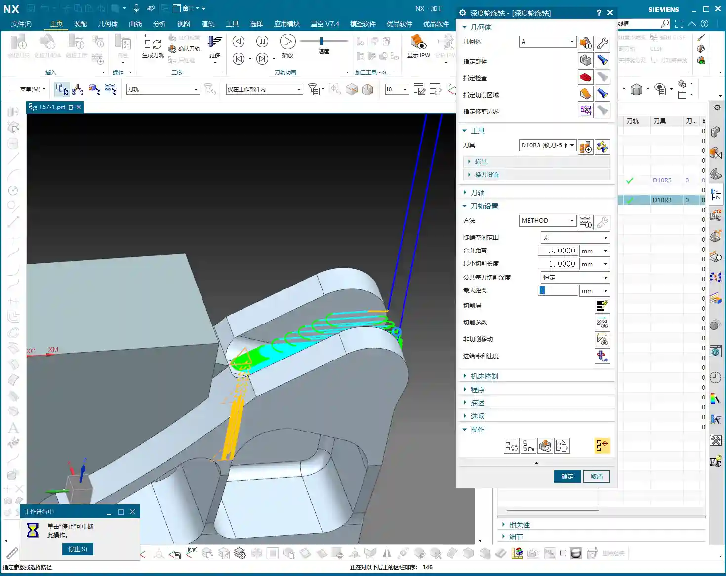
    4. IPW Verification: Machining Allowance & Cutting Effect

    Every time you make an adjustment, remember to check it using IPW (In-Process Workpiece). This feature shows you the actual effect of the tool after cutting and the remaining material allowance. With IPW, we can confirm that this area has indeed been milled out, and no corners or edges were missed. Don’t wait until the part is off the machine to find problems; by then, it’ll be too late to cry about it.

    5. Toolpath Optimization: Overcutting and Pragmatism

    In some non-critical areas, like corner transitions, the toolpath might show slight “overcutting”. As long as it’s not excessive and doesn’t affect assembly or performance, we can accept it. After all, striving for 100% perfection can sometimes sacrifice efficiency. In the workshop, we aim for “functional and sufficient”, not theoretical optimality from a textbook.

    For finishing pass toolpaths, besides Climb Milling, you can also try adjusting the parameters for “Smoothing” and “Area Linking”. This makes the tool engagement and retraction smoother, reducing tool marks. Think of it like driving: you want smooth acceleration and turns, not sudden braking and stops.

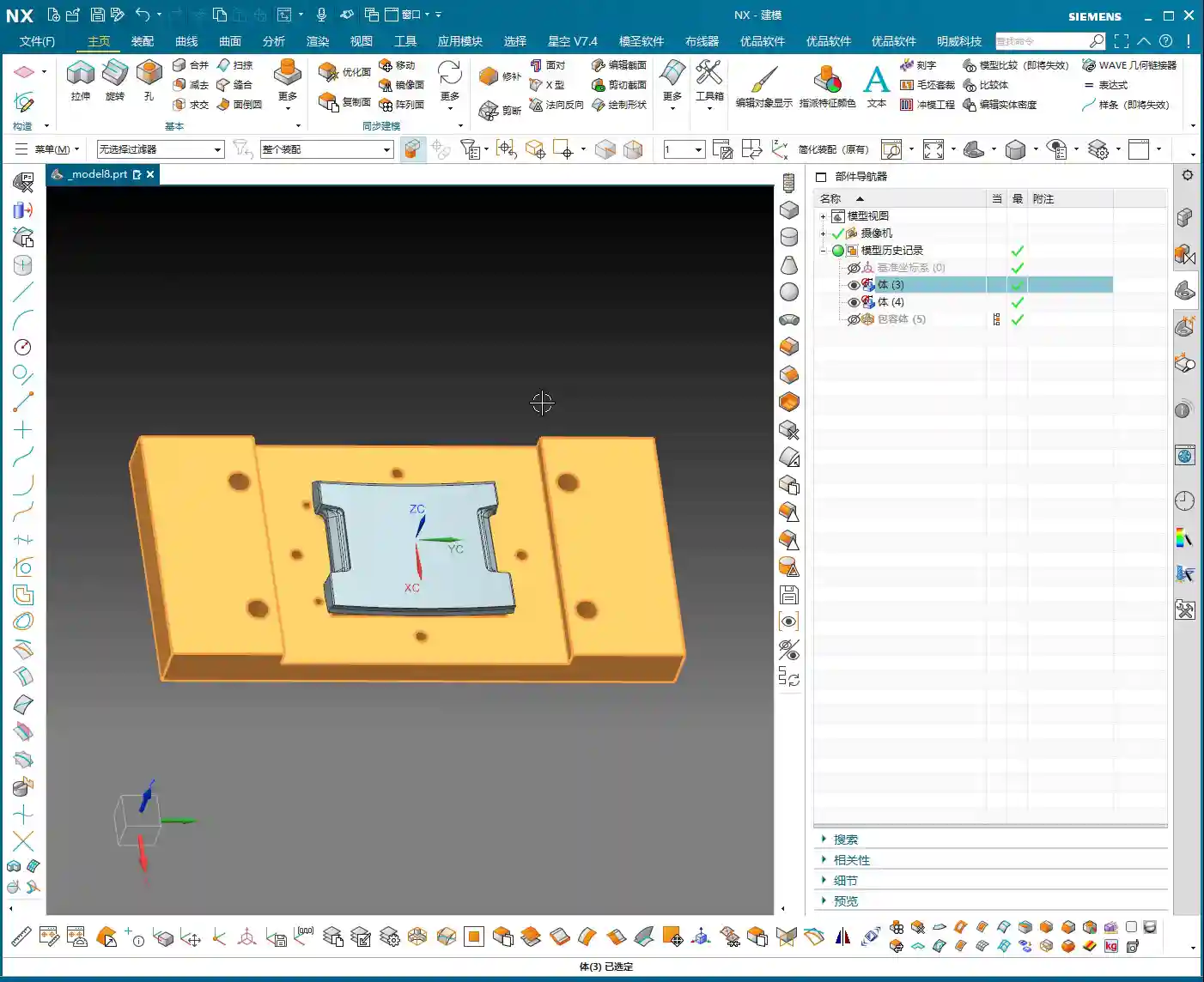
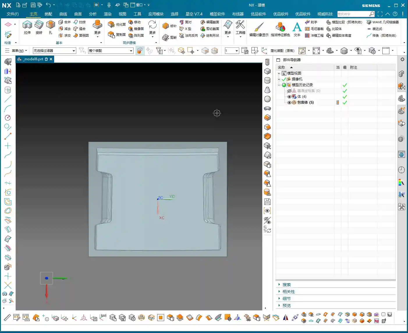
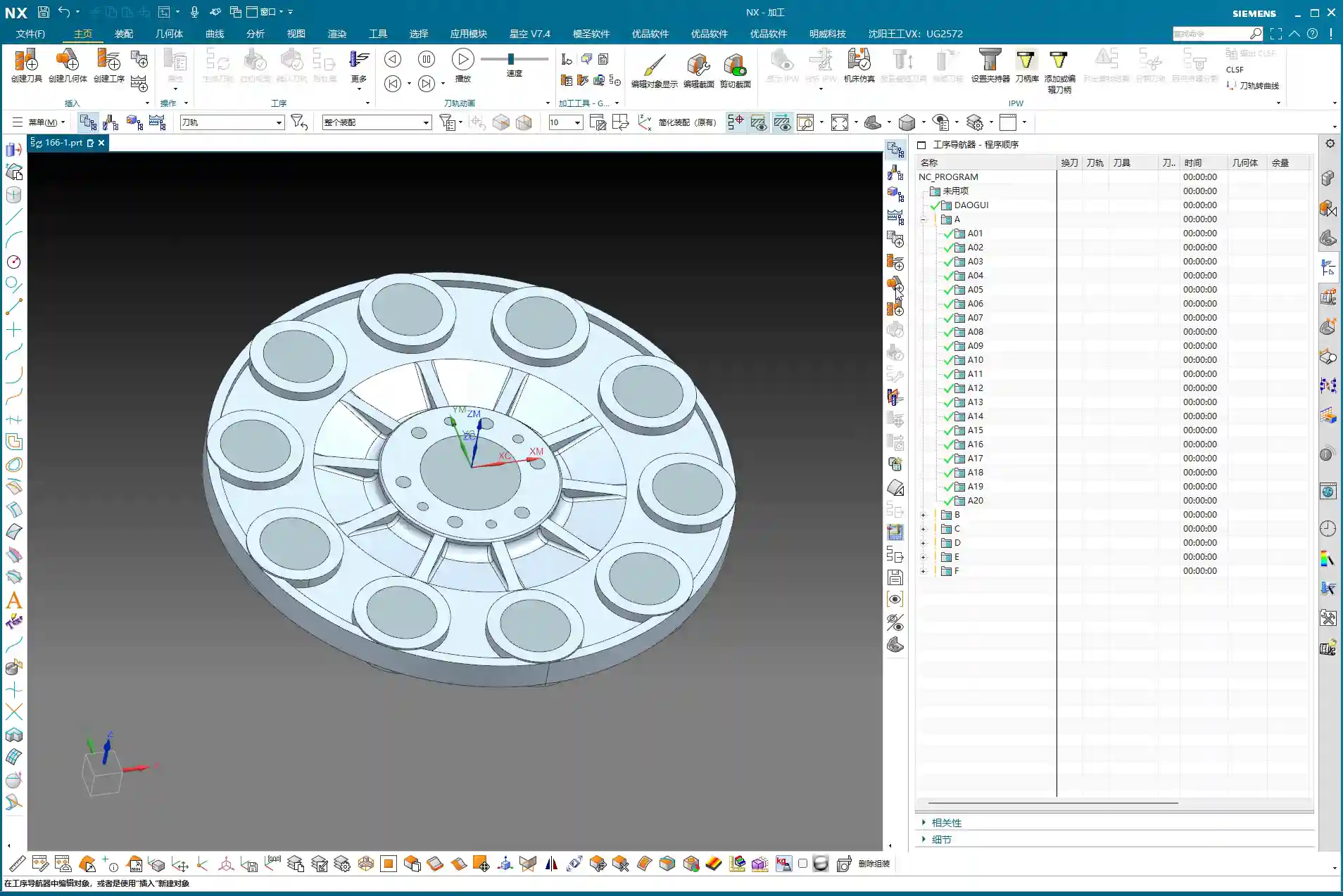
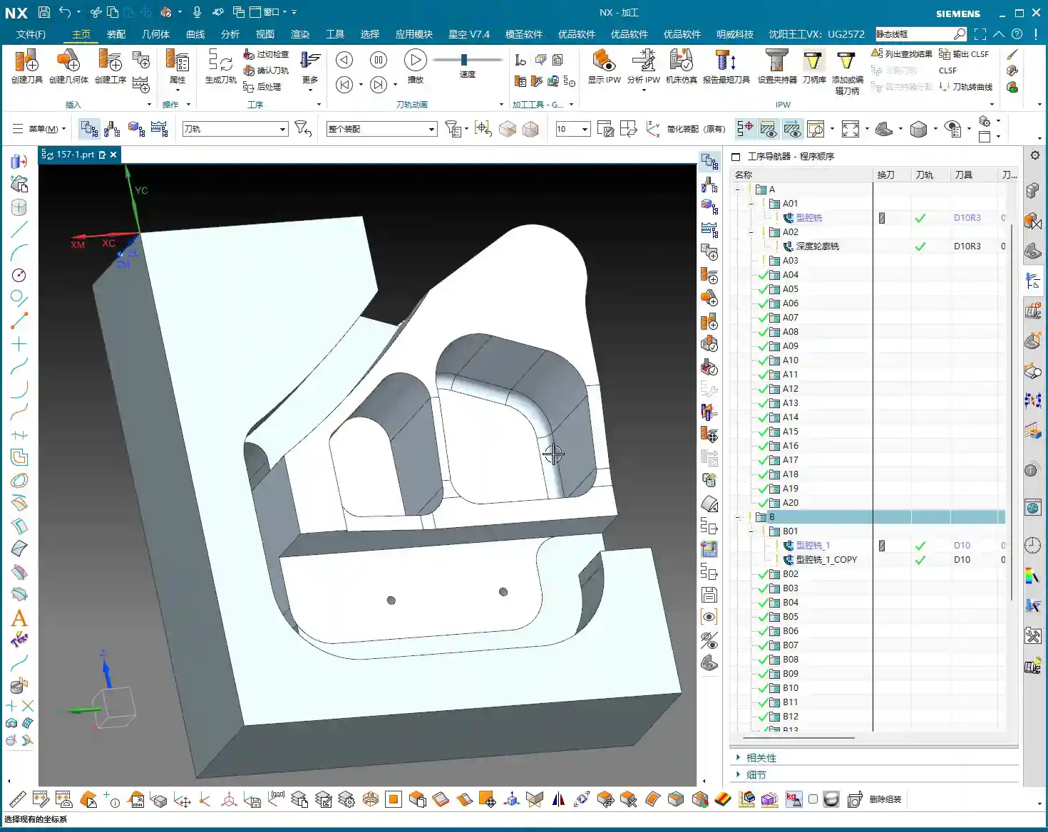
    II. Backside Machining: Coordinate System Switching, Roughing and Finishing

    Front side’s done. Next, flip the part over and machine the backside. Backside machining isn’t just copy-pasting; the coordinate system, toolpaths, and allowances all need a fresh review.

    1. The Critical WCS (Work Coordinate System) Switch

    For backside machining, the first and most crucial step is to switch the Work Coordinate System (WCS). You need to move the machine’s “eyes” to the backside of the part, otherwise, the tool will just be cutting air. Set the WCS on a critical plane on the backside, ensuring the Z-axis direction is correct. This is fundamental, but also the easiest place to make a mistake; once the WCS is wrong, the entire program is junk.

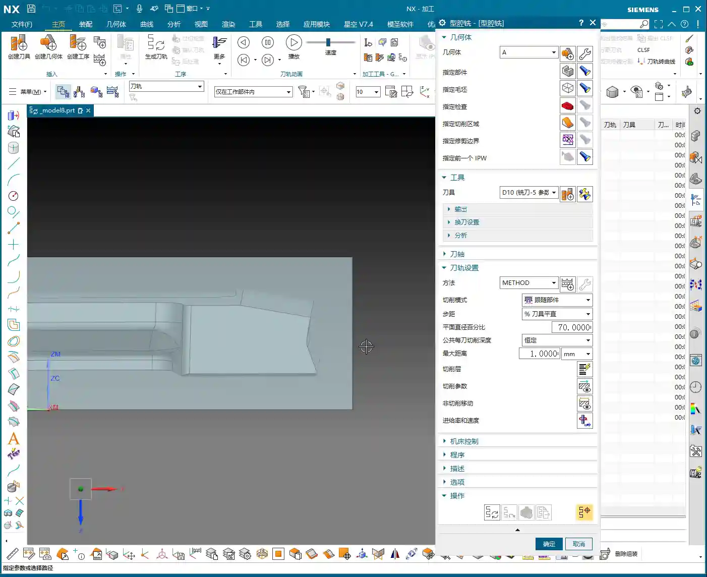
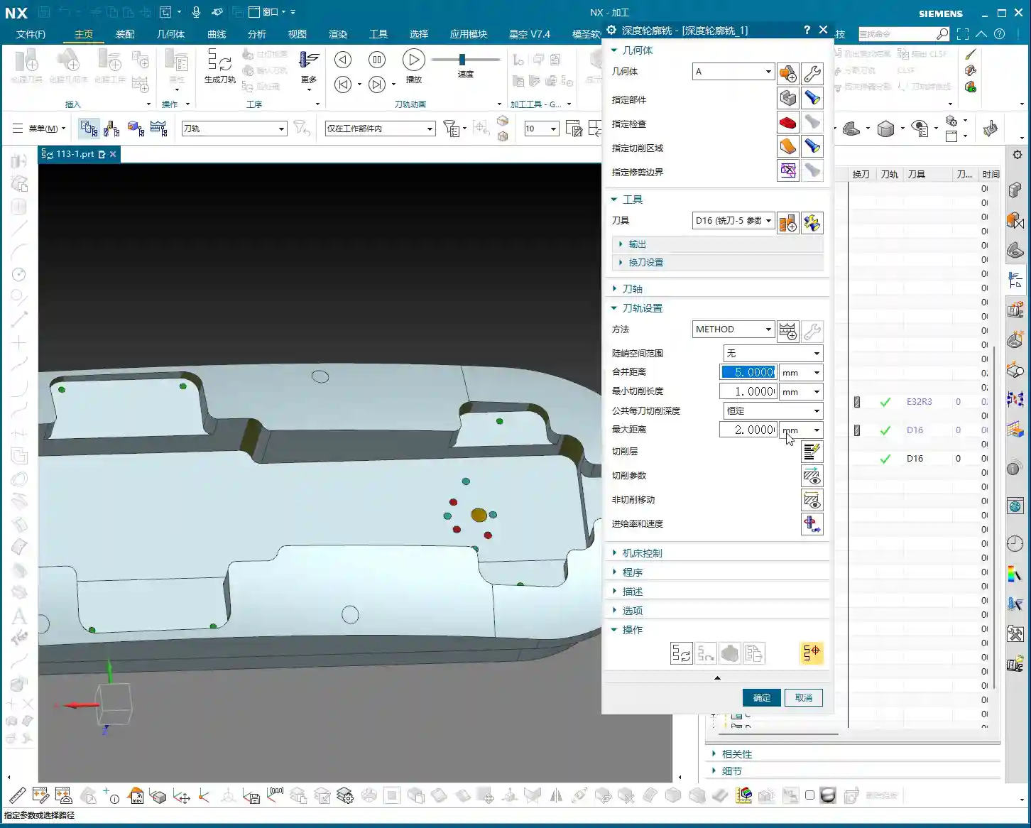
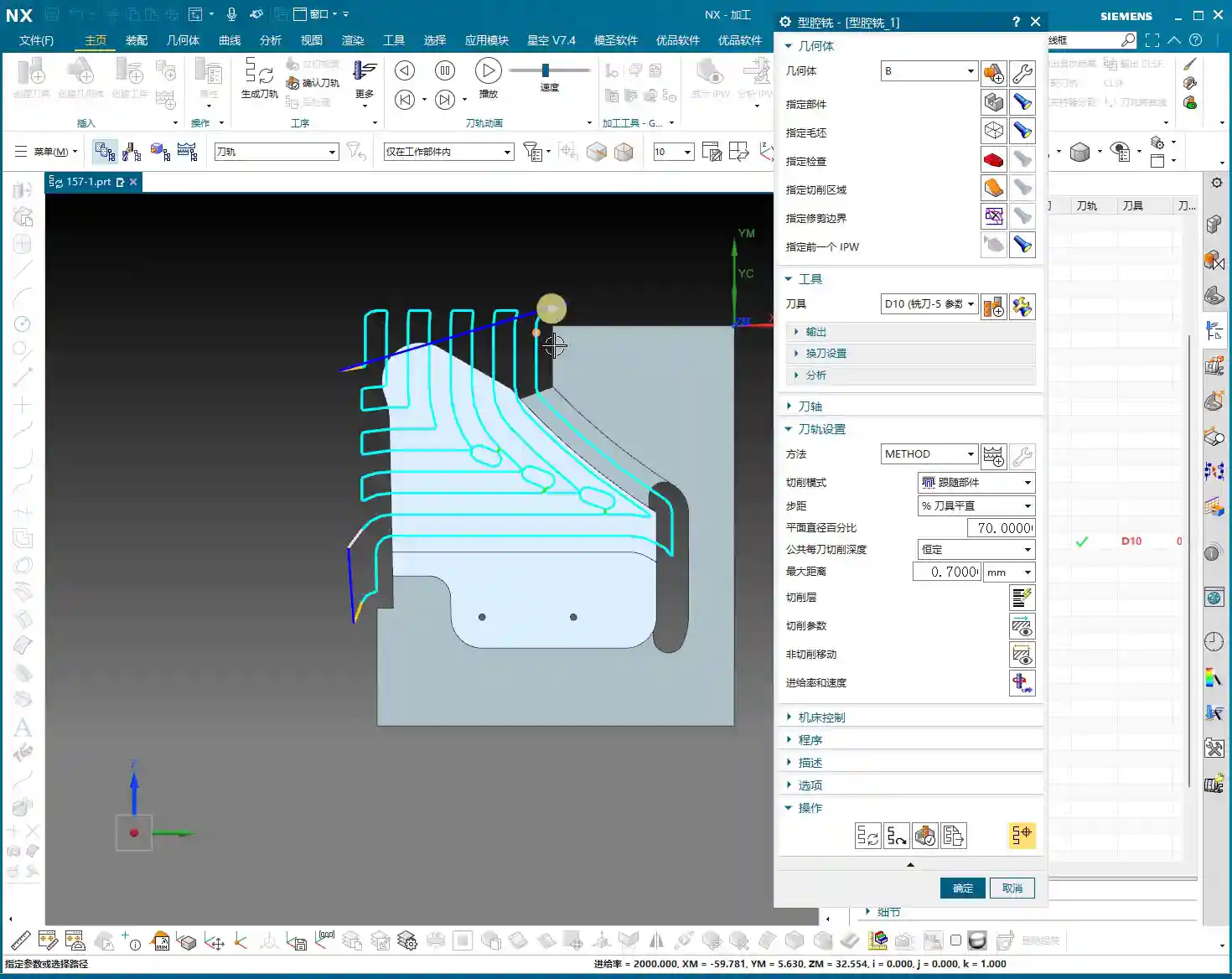
    2. Backside Roughing: Face Milling Strategy and Cut Level Control

    For the backside, we usually start with roughing. We can use “Cavity Milling” or Face Milling to quickly remove material. For example, using a 10 mm end mill, the single Depth of Cut (DOC) can be set to 0.7 mm. Here’s the key: how do you control the milling depth? You need to specify the “final cut level” on the machining plane, ensuring the tool mills precisely to your target surface. This effectively prevents overcutting or undercutting.

    The toolpaths for backside roughing might also be a bit “meandering.” As long as it doesn’t affect machining quality and part strength, a slightly irregular toolpath is fine. The machining allowance should be appropriate; don’t leave too much, or your finishing operations will be overly burdened.

    3. Backside Finishing Pass: Finishing the Bottom Surface & Toolpath Trimming

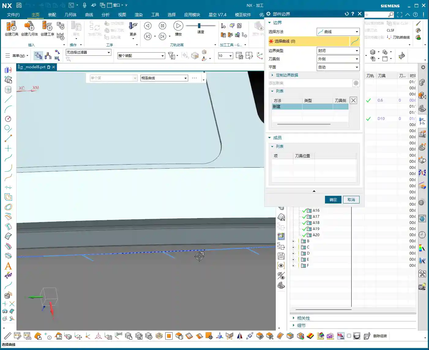
    After roughing, it’s time for the backside bottom surface finishing operation. Here, our goal is to mill the bottom surface clean, so set the Depth of Cut (DOC) to 0, and the floor stock to 0, ensuring the tool follows the plane tightly.

    But here’s a pitfall: the system-generated toolpath might “cut into” some areas inside the part that shouldn’t be touched. This won’t do! We need to use the “Trim” function to manually remove those unnecessary toolpaths. By selecting points, lines, or faces, you tell the software where the tool should stop. Remember, the toolpath must “stay within” but not run outside or enter forbidden areas. That’s how you ensure part integrity and accuracy.

    III. Backside Drilling: Efficient Layout and Depth Control

    The final step in backside machining is usually drilling. This looks simple, but it’s a job that demands both efficiency and accuracy.

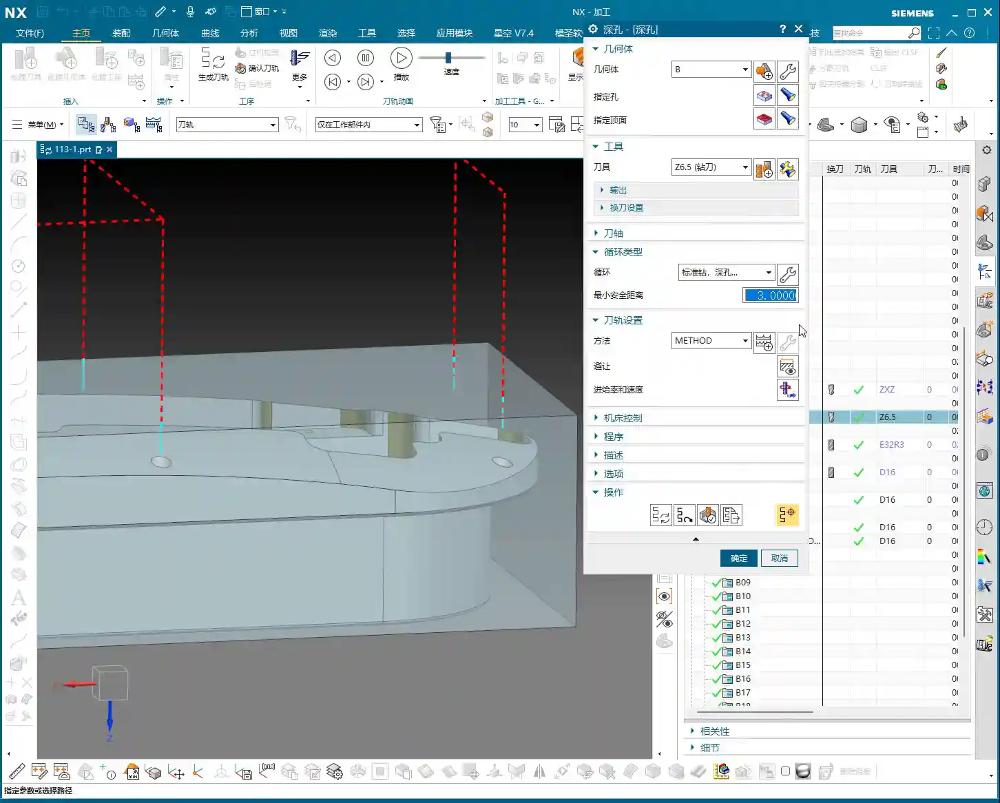
    1. Drilling Strategy: To Spot Drill or Not To Spot Drill

    For small holes like 2.1 mm, we can consider whether to use “Spot Drilling”. Theoretically, spot drilling prevents the drill from walking at the start, improving accuracy. But in practice, if the hole diameter isn’t large, the material is relatively soft, and the drill has good rigidity, we can “drill directly”, skipping the spot drilling step to boost efficiency. However, for critical hole locations or large-diameter drilling, spot drilling is essential.

    2. Drilling Tools and Depth Control

    Select a 2.1 mm carbide drill to ensure cutting performance. Drilling depth is also crucial; if hole tolerances are tight, you need precise control. For example, if the target depth is 20 mm, we might actually drill a bit deeper, setting it to 23 to 25 mm, to ensure the drill tip fully penetrates. Of course, the specific value must be determined by the drawing and actual conditions – don’t blindly overdrill.

    When spot drilling, if the depth isn’t deep, a single pass is sufficient to avoid multiple engagements and retracts. At the same time, pay attention to the angle of the spot drill; this directly affects the hole’s chamfer. Don’t let the chamfer get too large and impact subsequent assembly.

    Summary: Pitfall Avoidance Guide

    1. The Core of Siemens NX Programming: Combining Theory with Practice

    Textbook theory is important, but workshop experience is even more valuable. Siemens NX programming isn’t about rigid formulas; it requires you to flexibly adjust based on actual material, machine condition, and part requirements. Don’t just look at parameters; visualize how the tool moves on the workpiece. The cutting sound, sparks, and chips are all indicators for judging toolpath quality.

    2. Master Your Tools, Don’t Be Mastered by Them

    Software like Siemens NX is powerful, but it’s just a tool. A true programming expert masters the tools, rather than being led by them. Check IPW and toolpath simulations, but ultimately, rely on the physical part. When you encounter issues, don’t be afraid to modify; persistent trial-and-error is how you find the most suitable solution.

    3. Strive for Perfection, But Prioritize Efficiency and Cost

    Over-optimization wastes time, especially in teaching and beginner stages. In actual production, we need to maximize efficiency and reduce costs while ensuring quality. Some minor unnecessary retracts or non-excessive overcutting can be acceptable in certain situations. Learning to strike that balance – that’s the mark of a seasoned veteran.

    Alright, that’s it for today’s lesson. Go practice yourselves; with Siemens NX, mastery comes with practice!

    👤 About the Author:
    The author is a veteran CNC machining professional with 15 years of industry experience, specializing in UG NX programming. This article is an original work representing personal practical insights.

    ⚠️ Copyright Notice: Unauthorized reproduction or distribution without prior communication is strictly prohibited.

  • Master Wang, Siemens NX Expert: Backside Programming for Graphite Freeform Parts, Manual Toolpath Op

    📝 Key Takeaways:

    Practical Backside Machining of Graphite Freeform Parts

    Hello everyone, I’m Master Wang. Today, we’re cutting…

    [VIDEO_HERE]

    Hello everyone, I’m Master Wang. Today, we’re cutting straight to the chase – backside programming for graphite freeform parts. This job looks simple, but it’s full of pitfalls. In previous process classes, I briefly touched upon the overall workflow, but theory without practice is useless. Today, we’ll walk through this program step-by-step. Listen carefully, these are practical tips I’ve gained from 15 years of hands-on experience on the shop floor; you won’t find them in textbooks.

    Part Characteristics and Overall Machining Strategy

    Challenges and Solutions for Graphite Material

    The part we’re machining is made of graphite. Graphite is brittle and prone to chipping, so cutting parameters and tool selection require special attention. This part is roughly 100×200 mm (approx. 4×8 inches) and not very thick, making it a typical freeform, complex surface part. Its difficulty lies in not having a flat datum surface like conventional parts, and it features many undercut surfaces.

    The ‘Backside First’ Machining Strategy

    Listen up, you can’t machine this part directly from the front side to completion. Why? Because its backside has chamfers, or rather, undercuts. If you machine from the front, you’ll either hit the tool, collide with the workpiece, or simply won’t be able to reach. Therefore, our strategy is ‘backside first’.

    Step One (Backside Roughing): Start by machining the ‘backside’ of the raw material. Why start from the ‘backside’? Because the front side has complex locating features, and the backside has many undercut features. Machining the backside first allows for secure clamping/fixturing using the remaining material of the blank. Remember, during roughing, don’t machine all the way through; leave some stock, machining only about halfway. Also, rough out any other reachable areas. This ensures reliable clamping datums and material allowance for subsequent frontside machining.

    Step Two (Frontside Finishing Pass): Once the backside machining is nearly complete, flip the part over. Now, the ‘backside’ we just machined serves as the locating datum surface, resting directly on our fixture.
    Listen up, this is where the real skill comes in. To ensure high-precision locating at ±0.005mm, we machined locating pins into the fixture. Place the part, push it against the locating pins for a tight fit, then secure it with clamps.
    With the clamps in place, first rough out the accessible areas. Then, reposition the clamps and machine the areas that were previously covered. This breaks down the entire machining process into one backside operation and two frontside operations, a total of three steps, ensuring both precision and efficiency.

    Siemens NX Programming in Practice: From Raw Material to Finish Cut

    Tool Selection and Strategy (Customer Specified)

    For this job, the customer supplied all the tools directly, which I really respect about their process planning. We were given three tools: one D10 flat end mill, one D6 ball end mill, and a D10 lollipop cutter specifically for undercuts.
    Don’t ask me why these sizes, the customer provided them, but from a practical machining perspective, this tool configuration is quite reasonable. The D10 flat end mill handles large-area roughing, the D6 ball end mill takes care of various surface finishing passes, and the D10 lollipop cutter is the perfect tool for tackling those undercuts and deep cavities. Graphite cutting wears out tools quickly, so choosing the right tools and using them effectively saves money!

    Work Coordinate System (WCS) Setup – The Foundation of Precision

    Locating is the soul of machining. In Siemens NX, the Work Coordinate System (WCS) setup directly impacts machining precision. My habit is to choose a stable, easily measurable ‘bottom surface’ as the origin for complex parts like this. This way, no matter how many times you flip the part, the datum remains consistent. Today, we’ll set our WCS at the bottom surface origin.
    Raw material on layer 100, fixture on layer 200 – organized and clear at a glance.

    Backside Roughing: Stock Allowance is Key

    Now let’s program the backside roughing operation. We’ll use the D10 flat end mill.
    Core Point: Leave a 0.23mm machining allowance on the outer profile. This 0.23mm isn’t arbitrary; it’s an empirical value derived from repeated testing and fixture matching. Why leave it? Because when you flip the part and use the locating pins, the pins need to rest against a solid surface. If you finish to size directly, the part will wobble when the pins push against it, and precision will be impossible to guarantee! This 0.23mm is the ‘meat’ reserved for the locating pins, ensuring repeatable positioning accuracy for subsequent fixturing.
    At the same time, the Depth of Cut (DOC) should not go all the way to the final bottom; lift it slightly, for example, leave 5mm stock in the Z-axis. The undercut areas at the bottom will be handled by the lollipop cutter later. This both protects the flat end mill and provides enough space for the specialized tool to intervene later.

    Siemens NX’s ‘Draft Analysis’ is an excellent tool; it quickly helps you identify which surfaces are undercuts. Looking at our part, the areas visible when viewing from the backside upwards are the undercut surfaces that require special attention. Using a lollipop cutter for these undercuts is most effective and helps avoid tool collisions.

    Side Wall Finish Cut: The Challenge of Complex Surfaces

    After roughing the outer profile, the next step is the side wall finish cut. This is a painstaking job because almost the entire part consists of freeform surfaces, with no flat datum surfaces to work from.
    Traditional ‘Planar Profile Milling’ or simply selecting surfaces for toolpaths are ineffective, and sometimes the program won’t even generate. Don’t just trust fancy software simulations; when you run it on the actual machine, sparks (graphite generates dust) will fly everywhere, and that’s a bad sign.
    My approach is to use the 0.23mm stock allowance left from the previous roughing operation, combined with Siemens NX’s ‘Surface Contour Milling’. By precisely controlling boundaries and using an appropriate cutting strategy, we evenly remove the side wall stock. I won’t go into details here; I’ll demonstrate it directly in Siemens NX later so you can see my exact operations.

    Summary: Pitfall Avoidance Guide

    1. Material Properties First: Graphite is brittle, so tool feed rate, spindle speed, and Depth of Cut (DOC) must be conservative. Err on the side of slower and shallower.
    2. Locating Datums are Critical: Complex parts lack ‘absolutely’ flat datums. You must learn to create datums, utilizing raw material allowance or specialized fixtures (e.g., locating pins, clamps) to ensure clamping stability and repeatable positioning accuracy.
    3. ‘Backside First’ Strategy: For parts with undercut features, starting the machining process from the ‘unfavorable’ backside can effectively circumvent the risks of frontside clamping interference and tool collisions.
    4. Stock Allowance Control is a Master Skill: Leaving a precise machining allowance (e.g., 0.23mm in this case) on critical locating surfaces is central to ensuring positioning accuracy for subsequent operations. This is practical experience rarely found in textbooks.
    5. Flexible Tool Selection: Facing complex surfaces and undercuts, relying on a single tool won’t work. You must skillfully use specialized tools like ball end mills and lollipop cutters. Combined with Siemens NX’s ‘Draft Analysis’ and ‘Surface Contour Milling,’ you’ll achieve more with less effort.
    6. WCS and Coordinate Management: Unified WCS management and layered file organization can effectively prevent machining errors caused by coordinate system confusion, improving programming efficiency.
    7. Trust Cutting Conditions, Not Just Simulation: Software simulation is, after all, just a simulation. During actual machining, observe the cutting conditions (e.g., graphite dust, cutting sound) and adjust parameters promptly to ensure tool and part safety.

    👤 About the Author:
    The author is a veteran CNC machining professional with 15 years of industry experience, specializing in UG NX programming. This article is an original work representing personal practical insights.

    ⚠️ Copyright Notice: Unauthorized reproduction or distribution without prior communication is strictly prohibited.

  • Disc-Type Part Backside Programming: Master Wang’s Hands-On Guide to Avoiding Machining Pitfalls and

    📝 Key Takeaways:

    Detailed Explanation of Disc Part Backside Programming

    Chapter One: Geometry Handling and Filleting Strategies

    1.1 Auxiliary Geometry Management: Layer Discipline

    “Listen up. In this line of work, the more complex your models get, the better your habits need to be. Look, these filleted faces – you can’t just let them mix with the original faces; that’s just a mess. My habit is to move all these auxiliary or temporarily generated faces to a separate layer, like layer 50. That way, it’s easier to find things later, clearer to modify, and you won’t accidentally select the wrong thing. That’s just asking for trouble!”

    “So, remember this: after sealing these faces, select them, Ctrl+J (Change Layer), throw them into an unused layer, like layer 50, then turn it off. Out of sight, out of mind, but you can instantly bring them back when needed. That’s what I call ‘strategic planning.’”

    1.2 Filleting Challenges and Practical Solutions

    “Next up is filleting. This disc part has some edges that need treatment. Initially, we might want to apply an R3 fillet here. But sometimes, software gets ‘quirky’ – you select too many edges, and it tends to create some strange, undesirable changes that just don’t look ‘right’ or perfectly smooth.”

    “When you hit this kind of situation, don’t panic! Don’t jump to conclusions; we need to troubleshoot.

    1. Parameter Adjustment: Try seeing if it’s a size issue. Change R3 to R2, or even R1, and check the result. Sometimes small fillets work, but larger ones ‘break.’ Of course, R0 won’t work – then there’s no fillet at all, that’s a logic problem.
    2. Delete and Redo: If parameter adjustments don’t fix it, just delete and start over, or try ‘Replace Face.’ It’s like repairing a faulty machine: first check the components, if that doesn’t work, replace them.
    3. Flexible Strategy: Here’s the most important point! Look at these two edges, top and bottom. If you try to fillet them together, the result isn’t good. This is when you need to think creatively: Not every area absolutely needs a fillet, and not every area needs to be filleted in one go.

    “Specifically for that small upper corner, I’ve decided not to fillet it for now, and only fillet the larger one below. Why? This is a trick you won’t ‘learn from books’ – you have to consider actual machining. For our subsequent roughing operation, we’ll use a 20mm flat end mill. Its main job is to mill the sidewalls and bottom flat surfaces. For a small fillet hidden above a sidewall like this, the tool simply can’t ‘reach’ it effectively, so it won’t make much difference.”

    “But! Pay attention to this ‘but’: if for finishing pass you use a ball nose end mill (e.g., a 6mm ball nose), and this fillet is relatively large, and you haven’t modeled it or it’s not modeled to standard, then after machining, that area will definitely have a ‘witness mark’ or ‘step’. Then the bench hand will have to manually clean it up, which is time-consuming, laborious, costly, and could affect accuracy and surface finish! So, any required radius (R-angle) must be modeled correctly!”

    “When performing the operation, if you can’t select multiple edges at once for filleting, then select them separately, one edge at a time. Don’t think of it as a hassle; this is about being responsible for the part and for your program.”

    1.3 Siemens NX “Predict” Function: Early Risk Insight

    “In Siemens NX, there’s a function called ‘Predict’, which is different from ‘Preview.’ Preview just gives you a rough idea of the effect, but Predict highlights all geometry affected by your current operation. This function is great because it helps you see potential problems in advance, preventing blind operations. So, every time you’ve selected your edges, remember to click ‘Predict’ to ensure your selection is correct and the affected area is right, before clicking OK!”

    1.4 Final Geometry Processing: From Parametric to Solid

    “All modeling operations, especially things like filleting, come with parameters. Once we’ve finished processing the entire part’s geometry and confirmed the model is good, the final step is to remove all these parameters, turning it into a ‘final body,’ essentially a pure solid model. This makes the model look ‘cleaner’ and simplifies subsequent programming operations. After all, what we ultimately need is a tangible part, not a stack of combined parameters.”

    Chapter Two: Practical Backside Machining Programming

    2.1 Programming Fundamentals: Work Coordinate System and Blank Definition

    “Alright, geometry’s handled; let’s get into programming. Programming is like building a house: the Work Coordinate System (WCS) is the foundation, and if the foundation isn’t stable, the whole structure will be off-kilter. For this part’s backside machining, the coordinate system was already defined in the previous lesson, so just use that. Remember, for every new setup or side you’re machining, the WCS must be redefined or you need to ensure it’s correctly set up according to your fixturing and part orientation.”

    “Next is creating the geometry, including the workpiece and the blank. We’ve talked about this operation before, so I won’t belabor it. But one thing to emphasize: select ‘Workpiece’, don’t pick something like ‘Cavity Milling’ – those are not the same thing. For the Workpiece (Part), select our processed ‘A-1’ model. For the Blank, select the one we put on layer 100 earlier. Once the blank is selected, hide it so it’s not in the way and doesn’t confuse you.”

    2.2 Roughing Strategy: Efficiency and Stock Control

    “For roughing, it’s all about efficiency and safety. This disc part mostly consists of sidewalls and flat surfaces, so we’ll go straight with a 20mm flat end mill, using a ‘Cavity Milling’ approach. Why not use a ball nose or a radius end mill? I mentioned it earlier: ball nose cutters will leave fillets everywhere, adding extra work for subsequent corner cleanup. For roughing, stick with a flat end mill – it’s straightforward, aggressive, and highly efficient.”

    “For the depth of cut (DOC), which is the cutting depth per layer, we’ll set it to 0.7mm. This value is a comprehensive consideration of the tool, material, and machine rigidity. There’s no absolute rule, but this is a reliable empirical value. Feed rates and spindle speeds? We’ve covered those before – adjust them according to material properties. For example, faster for aluminum, slower for titanium alloys and stainless steel. Don’t use one set of parameters for everything; that’s asking for trouble.”

    “After generating the toolpath, you must check it with ‘Analyze IPW’ (In-Process Workpiece). This feature lets you see how much material is left on the part after roughing, and which areas weren’t cleared. Look, in those sharp corners and narrow regions, the 20mm tool definitely can’t reach, leaving behind material. That’s what I called a ‘witness mark’ earlier. These areas will need smaller tools to ‘sweep’ later. If the part doesn’t have a fillet, this will be a sharp corner with leftover material, and once a ball nose end mill goes through during finishing pass, that ‘witness mark’ will appear.”

    “Now, for stock allowance settings: this part doesn’t have extremely high precision requirements, so the material left after roughing can be adjusted. Set the blank stock to just 0.2mm. Don’t leave too much, or you’ll wear yourself out during finishing pass; but don’t leave too little either, or the roughing tool will easily dig in or even break. It’s a balance you have to find through experience.”

    2.3 Semi-Finishing Advancement: Details and Smoothing

    Roughing is ‘broad strokes,’ while semi-finishing is ‘fine detail.’ We’ll switch to a 10mm flat end mill to refine the stock left by roughing. The depth of cut (DOC) can be set to 0.5mm, and the stock allowance will remain 0.2mm, preparing for the final finishing pass.”

    “Before generating the program, let’s turn on the ‘Smooth’ function and give it a maximum value, like 400. This function is great; it makes the toolpaths smoother, reduces machine shock, and improves machining quality and tool life. However, don’t expect it to solve all problems. If two points are too far apart, or the geometry itself doesn’t allow it, it won’t be able to ‘smooth’ it out, and that’s normal – don’t fight the software.”

    “And for the stepover, which is the lateral feed rate, set it to roughly half of our roughing depth of cut (DOC). For instance, if the roughing depth of cut (DOC) was 0.7mm, here you can adjust it to 0.3mm. This value isn’t fixed; a little more or less is fine, as long as it ensures effective corner cleanup.”

    “After generating the toolpath, remember to turn on the ‘Gouges’ check. While theoretically there shouldn’t be any gouging, an extra layer of protection never hurts. If the model wasn’t processed correctly somewhere, or parameters were set wrong, it can alert you in time, preventing tool crashes that could damage the workpiece and tooling.”

    “Regarding reference tools, you can set them if you really want to avoid machining certain areas. But for a part like this, after semi-finishing, most areas will be cleaned up. Any remaining tight corners can be handled with a small ball nose end mill during the finishing pass. Often, programming requires adaptability; don’t be confined by software functions. You need to assess the actual situation to determine what should be done, what can be omitted, and how to achieve the lowest cost and highest efficiency.

    Summary: Pitfall Avoidance Guide

    1. Geometry management is fundamental: Cultivate good layer management habits, especially for auxiliary geometry. This significantly boosts efficiency and reduces errors.
    2. Filleting requires ‘situational awareness’: Selectively apply fillets in different areas, considering the actual machining tools and precision requirements. Pay special attention to how flat end mills versus ball nose end mills affect radii to prevent ‘witness marks.’
    3. Make good use of the Siemens NX “Predict” function: Before finalizing geometry operations, use “Predict” to identify potential issues early and avoid rework.
    4. From parametric to solid: After modeling is complete, remove parameters to make the model a “final solid body,” reducing potential issues in subsequent programming.
    5. WCS and blank definition must be precise: This is the foundation of programming; don’t be careless. Ensure it’s correct.
    6. Roughing strategy should be ‘simple and aggressive’: Prioritize using flat end mills for efficiency and to avoid generating unnecessary radii.
    7. IPW analysis is your ‘all-seeing eye’: Always analyze residual material after each roughing pass to understand which areas require subsequent corner cleanup, so you know exactly what to expect.
    8. Stock allowance and depth of cut (DOC) are based on experience: There’s no fixed formula. Adjust flexibly based on material, tool, machine, and precision requirements. Practice and explore.
    9. “Smooth” function improves toolpath quality: Judiciously use smoothing to make toolpaths more fluid, but understand its limitations.
    10. Always keep ‘Gouges’ check on: This is your last line of defense, ensuring toolpath safety and preventing damage to the machine and workpiece.

    “Remember these points, get your hands dirty, observe the sparks and sounds of the machine cutting, and analyze the machined parts. Slowly but surely, you’ll become a master yourself! Theory alone won’t cut it; you have to do the work and really think things through!”

    👤 About the Author:
    The author is a veteran CNC machining professional with 15 years of industry experience, specializing in UG NX programming. This article is an original work representing personal practical insights.

    ⚠️ Copyright Notice: Unauthorized reproduction or distribution without prior communication is strictly prohibited.

  • Siemens NX Backside Machining Practical Guide: Avoiding Coordinate System, Remnant Material, and Dri

    📝 Key Takeaways: Master Wang provides a hands-on guide to practical backside machining in Siemens NX. From Work Coordinate System setup to corner radius end mill corner cleanup and deep pocket side wall finishing, he thoroughly analyzes remnant material handling and toolpath optimization. He also sternly points out the “bloody lesson” of incorrect drilling sequencing, rejecting theoretical discussions and focusing solely on practical shop floor insights and cost efficiency.

    Hello everyone, this is Master Wang. Today, let’s skip the fluff and get straight to the facts. The job at hand is backside machining of a part. Many people think backside machining is just flipping the part over and repeating the process – it’s not that simple! There’s a lot more to it, especially subtle details that textbooks might not tell you. Listen closely, today we’re going to clarify the ins and outs of backside machining from start to finish.

    Chapter 1: Preparations for Backside Machining – Coordinate Systems and Blanks

    Precise Positioning: Work Coordinate System (WCS) Setup

    For backside machining, the Work Coordinate System (WCS) is paramount. Get this wrong, and everything that follows is pointless – you might even crash the tool!

    • First, the Z-axis needs to be set correctly. Since it’s the backside, the Z-axis usually requires an offset. For example, if the part’s bottom face is 2 mm lower than the blank, then the Z-axis zero point must be set -2 mm lower. This isn’t just an arbitrary number; it requires precise measurement! Otherwise, if the tool stick-out isn’t calculated correctly, you might under-machine the part, or worse, crash into it.
    • The Y and X axes should be determined based on the part’s features. I typically align the Y-axis to one edge and the X-axis to another. If a face has already been machined previously, use that face as the reference. Remember, the tool offsetting point must be clearly defined; this is the starting point for all your machining operations.

    Blanks, Part Models, and Check Geometries: Siemens NX Fundamentals

    These are the most fundamental settings in NX: blank, part model, and check geometry – none can be omitted. But merely knowing this isn’t enough; you also need to understand:

    • Which areas were machined in the previous operation? The starting point for backside machining is the endpoint of the previous operation. If there’s remnant material from the previous op, you must account for it in subsequent machining.
    • In-Process Workpiece (IPW) analysis is an excellent feature that allows you to visually see where material remains. For instance, areas below that were originally part of the blank are now gone, because they were already machined during the front-side operation. Don’t be complacent; you need to thoroughly plan the entire machining sequence, ensuring smooth transitions between operations.

    Chapter 2: Refining Details – Corner Cleanup and Side Wall Machining

    Cleaning up Nooks and Crannies: Corner Cleanup with Radius End Mills

    Those nooks and crannies on the part are where remnant material loves to hide. For these areas, we need to perform Corner Cleanup using radius end mills. Initially, I might consider an R2 tool, but in practice, an R3 might be more suitable, or as mentioned in the video, a D16R0.8 (16mm diameter, 0.8mm radius). The choice of tool size depends on:

    • Stock allowance: The amount of material left during roughing directly impacts the difficulty of finishing pass corner cleanup.
    • Tool interference: If the tool is too large, it might not even fit, or it could gouge other surfaces.

    Don’t just rely on software simulations. No matter how pretty the simulation looks, if the sparks fly incorrectly when the tool engages on the machine, you’ve got a problem! For corner cleanup with radius end mills, the Depth of Cut (DOC) should be small, and the feed rate stable, otherwise, tool life will be severely compromised.

    Remnant Material Management: Patch Opening or N-Sided Surface

    After corner cleanup, you might find that some areas still have remnant material due to the limitations of the radius end mill, or there might be irregular holes that need to be addressed. For example, the “hole” in the video:

    • If chamfering is required later, it’s advisable to fill it in using the Patch Opening or N-Sided Surface functions. Don’t be lazy; rework later will be more troublesome and will negatively impact chamfer quality.
    • I typically place all these auxiliary bodies on Layer 55. This makes management easier, prevents confusion with the main part, and doesn’t interfere with subsequent toolpath calculations.

    Finishing Pass for Bottom Faces and Side Walls: Flat End Mill Strategy

    Finishing the bottom faces and side walls is where your expertise is truly tested. Don’t get the sequence wrong: first finish the bottom faces, then the side walls. This ensures the surface finish of the bottom face isn’t compromised by side wall machining.

    • Finishing the bottom face: Use a D16 (16mm diameter) flat end mill with zero stock allowance. The prerequisite is that roughing must be even; otherwise, an uneven finish on the bottom face indicates poor roughing.
    • Finishing the side walls (especially deep pockets): If the side walls are quite tall, plunging a single tool straight to the bottom is suicidal! The tool will wear quickly, chatter, or even chip. You must use multi-level machining (layered processing). The Depth of Cut (DOC) for each pass should be determined by the material and tool rigidity. For example, 5 mm (approx. 0.2 inch) per pass, with a side wall stock allowance of 0.5 mm (approx. 0.02 inch), then machined in several passes. This is often referred to as “depth milling” or “helical milling” functionality.

    Chapter 3: Major Practical Pitfalls and Optimization – The Fatal Error of Drilling Sequence

    Drilling Sequence: A Bloody Lesson Learned

    Listen up! This is today’s biggest pitfall! In the video, I just realized that the holes below haven’t been drilled yet. This is a classic machining sequence error!

    • These holes should have been drilled right at the beginning, even before finishing the bottom faces and side walls. Why?
    • Positioning difficulty: If you try to drill holes after the surfaces are already finished, precise positioning becomes challenging.
    • Surface damage: During drilling, the drill bit can leave scratches on the finished surface, or even cause chipping at the edge, directly ruining the results of your previous finishing passes.
    • Drilling on curved surfaces: If the hole location is on a curved surface, the difficulty increases significantly, as the drill bit can easily slip, leading to inaccurate hole positions.

    Therefore, when manufacturing parts, process planning must come first. Proceed step-by-step; don’t make assumptions. Let me reiterate: Drill the holes first, then finish the surrounding areas! This is an ironclad rule!

    Corrective Measures: Siemens NX Drilling Operations

    Since a mistake was made, we need to find a way to correct it. In NX:

    • First, use a spot drill to ensure the precise center location of the hole.
    • Then, perform the drilling through-hole operation, selecting all hole features that need to be drilled.
    • Starting plane: Remember to set it to the highest face of the blank, not the already finished surface. This avoids air cutting and saves machining time.

    While corrections can be made, it’s always better to do it right from the start. Remember this lesson!

    Summary: Pitfall Avoidance Guide

    1. WCS Positioning is Fundamental: The Work Coordinate System (WCS) for backside machining must be precise. The Z-axis offset and tool offsetting point are especially critical, directly impacting tool safety and machining accuracy.
    2. IPW Analysis is Essential: After each operation, always analyze the In-Process Workpiece (IPW) to confirm remnant material. This guides subsequent toolpath optimization, preventing air cuts or missed machining areas.
    3. Corner Cleanup with Radius End Mills: For complex features and internal corners, flexibly choose radius end mills. Determine the tool diameter and radius based on stock allowance and potential tool interference. Never try to finish all corners with just a flat end mill.
    4. Auxiliary Geometry Management: For features requiring patching (e.g., holes, faces), utilize NX’s “Patch Opening” and similar functions, and manage them with appropriate layering to ensure they don’t interfere with the main toolpath.
    5. Layered Finishing for Deep Pocket Side Walls: When machining tall side walls or deep pockets, multi-level machining is essential. Control the Depth of Cut (DOC) per pass to protect the tool and improve surface quality. Adjust side wall stock allowance and depth per pass according to actual conditions.
    6. Machining Sequence is an Ironclad Rule: CRITICAL POINT! Hole machining MUST be completed BEFORE finishing passes on flat surfaces! Otherwise, it’s highly prone to positioning difficulties, surface scratches, or chipping at the edges, leading to severe quality issues and increased rework costs. This is a bloody lesson learned!
    7. Don’t Just Rely on Simulation, Observe the Shop Floor: No matter how realistic software simulations appear, they cannot replicate the actual cutting sparks and sounds on the machine. Observe and feel more to truly master the secrets of machining.

    👤 About the Author:
    The author is a veteran CNC machining professional with 15 years of industry experience, specializing in UG NX programming. This article is an original work representing personal practical insights.

    ⚠️ Copyright Notice: Unauthorized reproduction or distribution without prior communication is strictly prohibited.