📝 Key Takeaways:
Detailed Explanation of Disc Part Backside Programming
Chapter One: Geometry Handling and Filleting Strategies
1.1 Auxiliary Geometry Management: Layer Discipline
“Listen up. In this line of work, the more complex your models get, the better your habits need to be. Look, these filleted faces – you can’t just let them mix with the original faces; that’s just a mess. My habit is to move all these auxiliary or temporarily generated faces to a separate layer, like layer 50. That way, it’s easier to find things later, clearer to modify, and you won’t accidentally select the wrong thing. That’s just asking for trouble!”
“So, remember this: after sealing these faces, select them, Ctrl+J (Change Layer), throw them into an unused layer, like layer 50, then turn it off. Out of sight, out of mind, but you can instantly bring them back when needed. That’s what I call ‘strategic planning.’”
1.2 Filleting Challenges and Practical Solutions
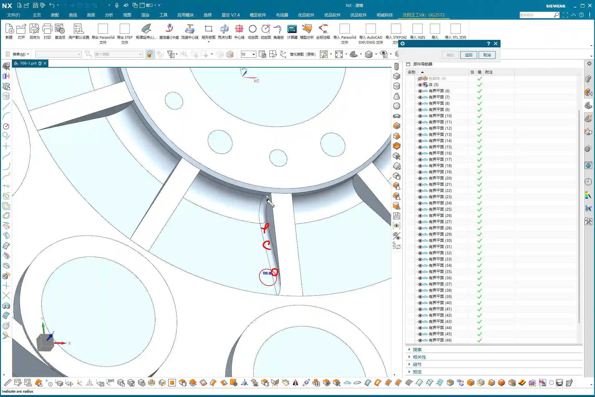
“Next up is filleting. This disc part has some edges that need treatment. Initially, we might want to apply an R3 fillet here. But sometimes, software gets ‘quirky’ – you select too many edges, and it tends to create some strange, undesirable changes that just don’t look ‘right’ or perfectly smooth.”
“When you hit this kind of situation, don’t panic! Don’t jump to conclusions; we need to troubleshoot.
- Parameter Adjustment: Try seeing if it’s a size issue. Change R3 to R2, or even R1, and check the result. Sometimes small fillets work, but larger ones ‘break.’ Of course, R0 won’t work – then there’s no fillet at all, that’s a logic problem.
- Delete and Redo: If parameter adjustments don’t fix it, just delete and start over, or try ‘Replace Face.’ It’s like repairing a faulty machine: first check the components, if that doesn’t work, replace them.
- Flexible Strategy: Here’s the most important point! Look at these two edges, top and bottom. If you try to fillet them together, the result isn’t good. This is when you need to think creatively: Not every area absolutely needs a fillet, and not every area needs to be filleted in one go.”
“Specifically for that small upper corner, I’ve decided not to fillet it for now, and only fillet the larger one below. Why? This is a trick you won’t ‘learn from books’ – you have to consider actual machining. For our subsequent roughing operation, we’ll use a 20mm flat end mill. Its main job is to mill the sidewalls and bottom flat surfaces. For a small fillet hidden above a sidewall like this, the tool simply can’t ‘reach’ it effectively, so it won’t make much difference.”
“But! Pay attention to this ‘but’: if for finishing pass you use a ball nose end mill (e.g., a 6mm ball nose), and this fillet is relatively large, and you haven’t modeled it or it’s not modeled to standard, then after machining, that area will definitely have a ‘witness mark’ or ‘step’. Then the bench hand will have to manually clean it up, which is time-consuming, laborious, costly, and could affect accuracy and surface finish! So, any required radius (R-angle) must be modeled correctly!”

“When performing the operation, if you can’t select multiple edges at once for filleting, then select them separately, one edge at a time. Don’t think of it as a hassle; this is about being responsible for the part and for your program.”
1.3 Siemens NX “Predict” Function: Early Risk Insight
“In Siemens NX, there’s a function called ‘Predict’, which is different from ‘Preview.’ Preview just gives you a rough idea of the effect, but Predict highlights all geometry affected by your current operation. This function is great because it helps you see potential problems in advance, preventing blind operations. So, every time you’ve selected your edges, remember to click ‘Predict’ to ensure your selection is correct and the affected area is right, before clicking OK!”
1.4 Final Geometry Processing: From Parametric to Solid
“All modeling operations, especially things like filleting, come with parameters. Once we’ve finished processing the entire part’s geometry and confirmed the model is good, the final step is to remove all these parameters, turning it into a ‘final body,’ essentially a pure solid model. This makes the model look ‘cleaner’ and simplifies subsequent programming operations. After all, what we ultimately need is a tangible part, not a stack of combined parameters.”
Chapter Two: Practical Backside Machining Programming

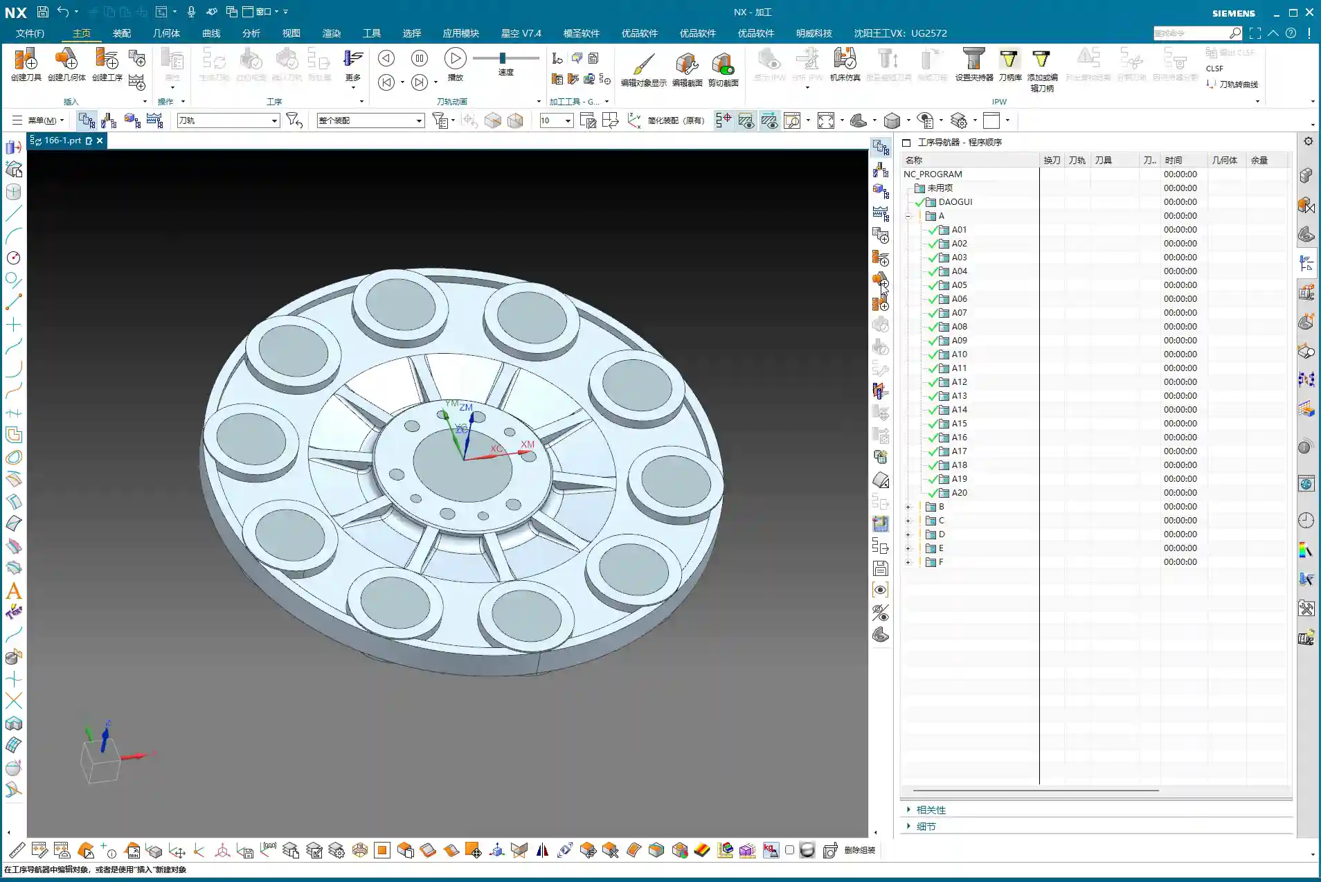
2.1 Programming Fundamentals: Work Coordinate System and Blank Definition
“Alright, geometry’s handled; let’s get into programming. Programming is like building a house: the Work Coordinate System (WCS) is the foundation, and if the foundation isn’t stable, the whole structure will be off-kilter. For this part’s backside machining, the coordinate system was already defined in the previous lesson, so just use that. Remember, for every new setup or side you’re machining, the WCS must be redefined or you need to ensure it’s correctly set up according to your fixturing and part orientation.”
“Next is creating the geometry, including the workpiece and the blank. We’ve talked about this operation before, so I won’t belabor it. But one thing to emphasize: select ‘Workpiece’, don’t pick something like ‘Cavity Milling’ – those are not the same thing. For the Workpiece (Part), select our processed ‘A-1’ model. For the Blank, select the one we put on layer 100 earlier. Once the blank is selected, hide it so it’s not in the way and doesn’t confuse you.”
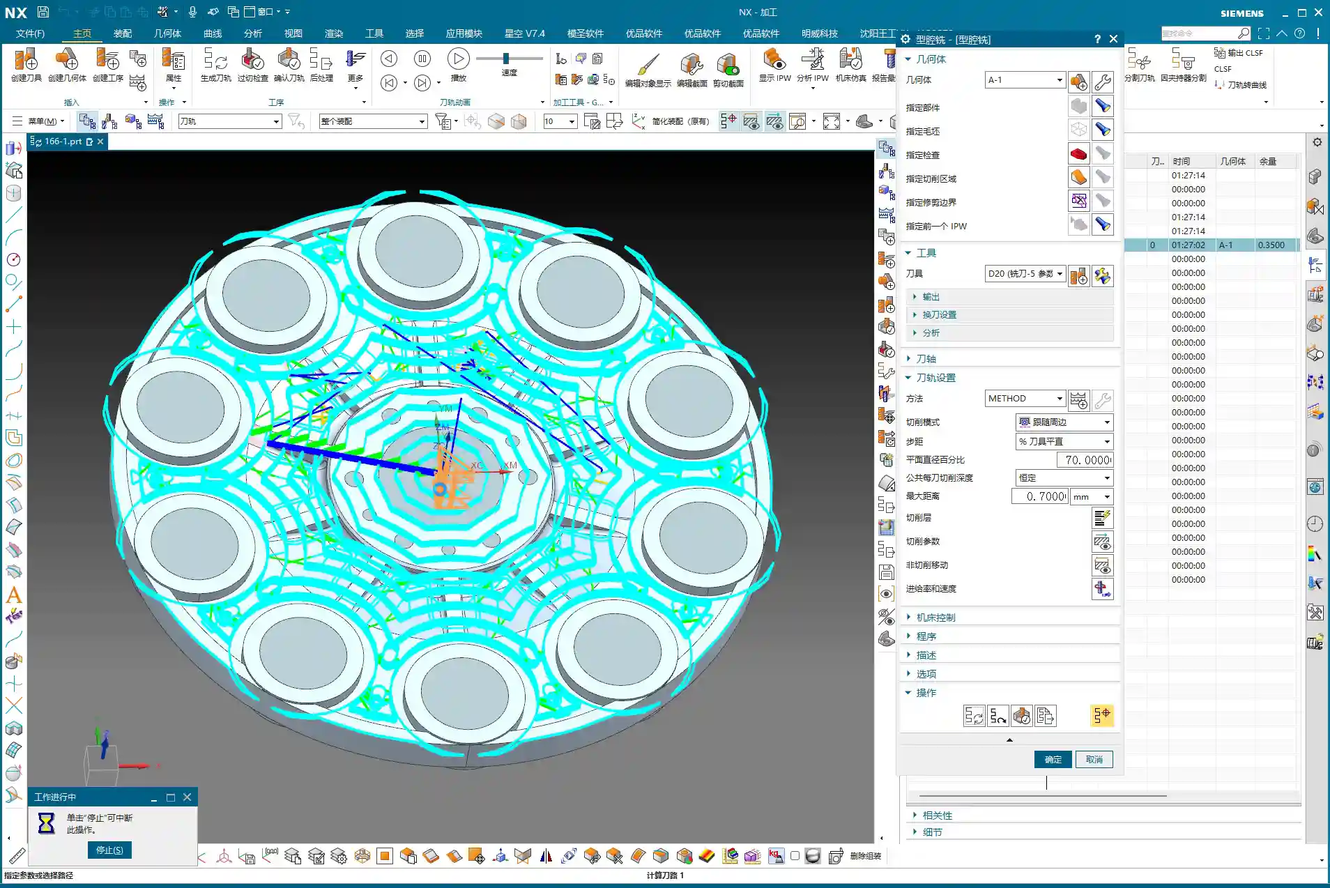
2.2 Roughing Strategy: Efficiency and Stock Control
“For roughing, it’s all about efficiency and safety. This disc part mostly consists of sidewalls and flat surfaces, so we’ll go straight with a 20mm flat end mill, using a ‘Cavity Milling’ approach. Why not use a ball nose or a radius end mill? I mentioned it earlier: ball nose cutters will leave fillets everywhere, adding extra work for subsequent corner cleanup. For roughing, stick with a flat end mill – it’s straightforward, aggressive, and highly efficient.”
“For the depth of cut (DOC), which is the cutting depth per layer, we’ll set it to 0.7mm. This value is a comprehensive consideration of the tool, material, and machine rigidity. There’s no absolute rule, but this is a reliable empirical value. Feed rates and spindle speeds? We’ve covered those before – adjust them according to material properties. For example, faster for aluminum, slower for titanium alloys and stainless steel. Don’t use one set of parameters for everything; that’s asking for trouble.”

“After generating the toolpath, you must check it with ‘Analyze IPW’ (In-Process Workpiece). This feature lets you see how much material is left on the part after roughing, and which areas weren’t cleared. Look, in those sharp corners and narrow regions, the 20mm tool definitely can’t reach, leaving behind material. That’s what I called a ‘witness mark’ earlier. These areas will need smaller tools to ‘sweep’ later. If the part doesn’t have a fillet, this will be a sharp corner with leftover material, and once a ball nose end mill goes through during finishing pass, that ‘witness mark’ will appear.”
“Now, for stock allowance settings: this part doesn’t have extremely high precision requirements, so the material left after roughing can be adjusted. Set the blank stock to just 0.2mm. Don’t leave too much, or you’ll wear yourself out during finishing pass; but don’t leave too little either, or the roughing tool will easily dig in or even break. It’s a balance you have to find through experience.”
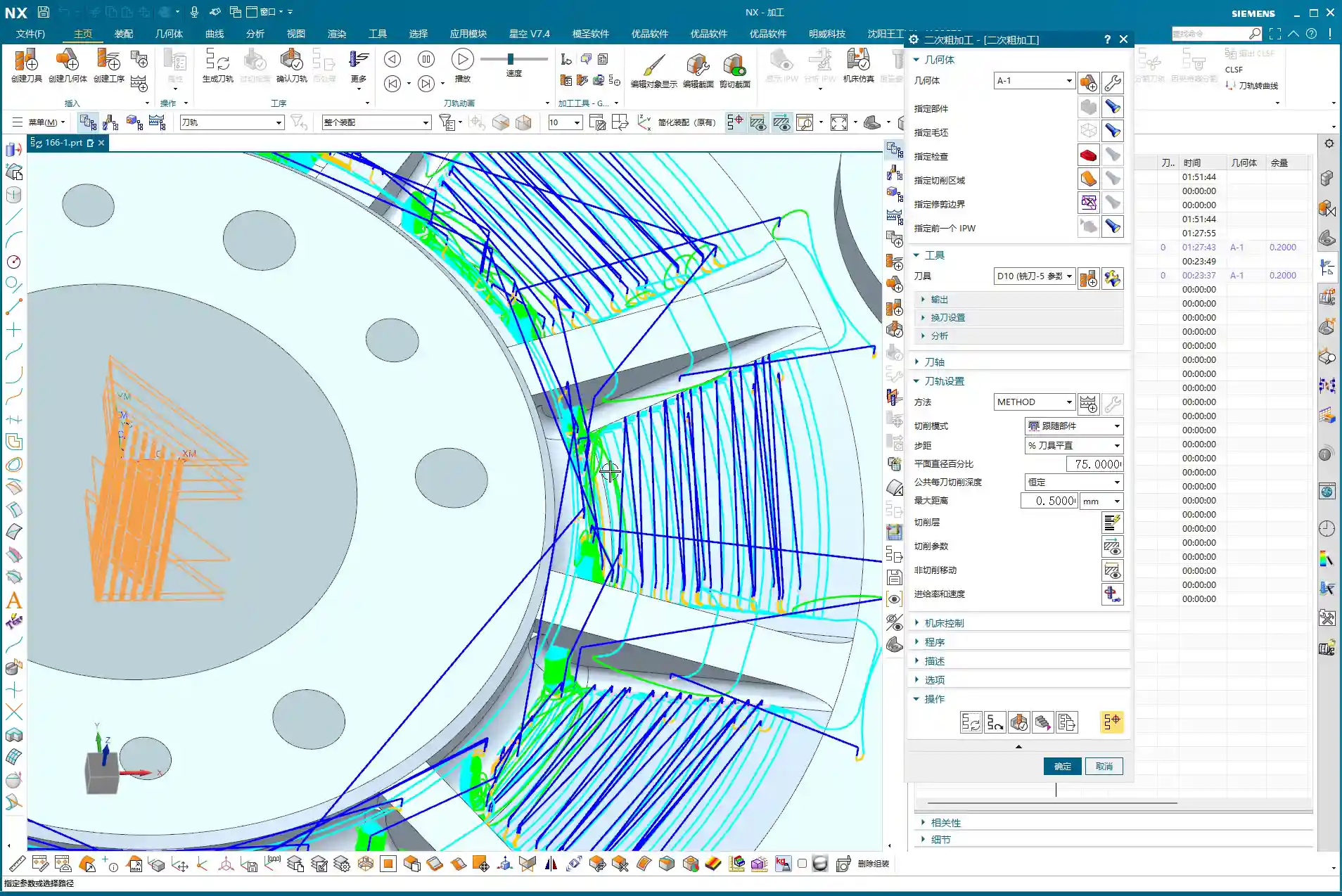
2.3 Semi-Finishing Advancement: Details and Smoothing
“Roughing is ‘broad strokes,’ while semi-finishing is ‘fine detail.’ We’ll switch to a 10mm flat end mill to refine the stock left by roughing. The depth of cut (DOC) can be set to 0.5mm, and the stock allowance will remain 0.2mm, preparing for the final finishing pass.”
“Before generating the program, let’s turn on the ‘Smooth’ function and give it a maximum value, like 400. This function is great; it makes the toolpaths smoother, reduces machine shock, and improves machining quality and tool life. However, don’t expect it to solve all problems. If two points are too far apart, or the geometry itself doesn’t allow it, it won’t be able to ‘smooth’ it out, and that’s normal – don’t fight the software.”

“And for the stepover, which is the lateral feed rate, set it to roughly half of our roughing depth of cut (DOC). For instance, if the roughing depth of cut (DOC) was 0.7mm, here you can adjust it to 0.3mm. This value isn’t fixed; a little more or less is fine, as long as it ensures effective corner cleanup.”
“After generating the toolpath, remember to turn on the ‘Gouges’ check. While theoretically there shouldn’t be any gouging, an extra layer of protection never hurts. If the model wasn’t processed correctly somewhere, or parameters were set wrong, it can alert you in time, preventing tool crashes that could damage the workpiece and tooling.”
“Regarding reference tools, you can set them if you really want to avoid machining certain areas. But for a part like this, after semi-finishing, most areas will be cleaned up. Any remaining tight corners can be handled with a small ball nose end mill during the finishing pass. Often, programming requires adaptability; don’t be confined by software functions. You need to assess the actual situation to determine what should be done, what can be omitted, and how to achieve the lowest cost and highest efficiency.”
Summary: Pitfall Avoidance Guide
- Geometry management is fundamental: Cultivate good layer management habits, especially for auxiliary geometry. This significantly boosts efficiency and reduces errors.
- Filleting requires ‘situational awareness’: Selectively apply fillets in different areas, considering the actual machining tools and precision requirements. Pay special attention to how flat end mills versus ball nose end mills affect radii to prevent ‘witness marks.’
- Make good use of the Siemens NX “Predict” function: Before finalizing geometry operations, use “Predict” to identify potential issues early and avoid rework.
- From parametric to solid: After modeling is complete, remove parameters to make the model a “final solid body,” reducing potential issues in subsequent programming.
- WCS and blank definition must be precise: This is the foundation of programming; don’t be careless. Ensure it’s correct.
- Roughing strategy should be ‘simple and aggressive’: Prioritize using flat end mills for efficiency and to avoid generating unnecessary radii.
- IPW analysis is your ‘all-seeing eye’: Always analyze residual material after each roughing pass to understand which areas require subsequent corner cleanup, so you know exactly what to expect.
- Stock allowance and depth of cut (DOC) are based on experience: There’s no fixed formula. Adjust flexibly based on material, tool, machine, and precision requirements. Practice and explore.
- “Smooth” function improves toolpath quality: Judiciously use smoothing to make toolpaths more fluid, but understand its limitations.
- Always keep ‘Gouges’ check on: This is your last line of defense, ensuring toolpath safety and preventing damage to the machine and workpiece.
“Remember these points, get your hands dirty, observe the sparks and sounds of the machine cutting, and analyze the machined parts. Slowly but surely, you’ll become a master yourself! Theory alone won’t cut it; you have to do the work and really think things through!”
👤 About the Author:
The author is a veteran CNC machining professional with 15 years of industry experience, specializing in UG NX programming. This article is an original work representing personal practical insights.
⚠️ Copyright Notice: Unauthorized reproduction or distribution without prior communication is strictly prohibited.
Leave a Reply