Tag: Depth of Cut

  • Siemens NX Cavity Milling Depth of Cut Explained: Master Wang Teaches You How to Control Toolpaths T

    📝 Key Takeaways: ** Master Wang provides an in-depth analysis of NX Cavity Milling’s machining layers, guiding you step-by-step on precise machining depth control, and differentiating between Automatic and User Defined modes. Understand the practical significance of multi-layer cutting, avoid tool wear and workpiece deformation, achieve high-efficiency and high-precision machining, and bridge the gap between theory and real-world application, addressing practical blind spots not found in textbooks. **

    Hey everyone, it’s Old Wang, Master Wang here. Today, picking up where we left off, let’s really dig into what this “Cavity Milling Machining Layer” in NX is all about. Don’t let the name intimidate you. This is crucial for our work, especially when milling deep cavities and hard materials, to boost efficiency, ensure accuracy, and even safeguard your tool’s lifeline! Textbooks might not fully explain it, but after fifteen years on the shop floor, I’m telling you, if you don’t master this, you’re in for some serious trouble.

    Machining Layers: The “Conductor” for Depth Control

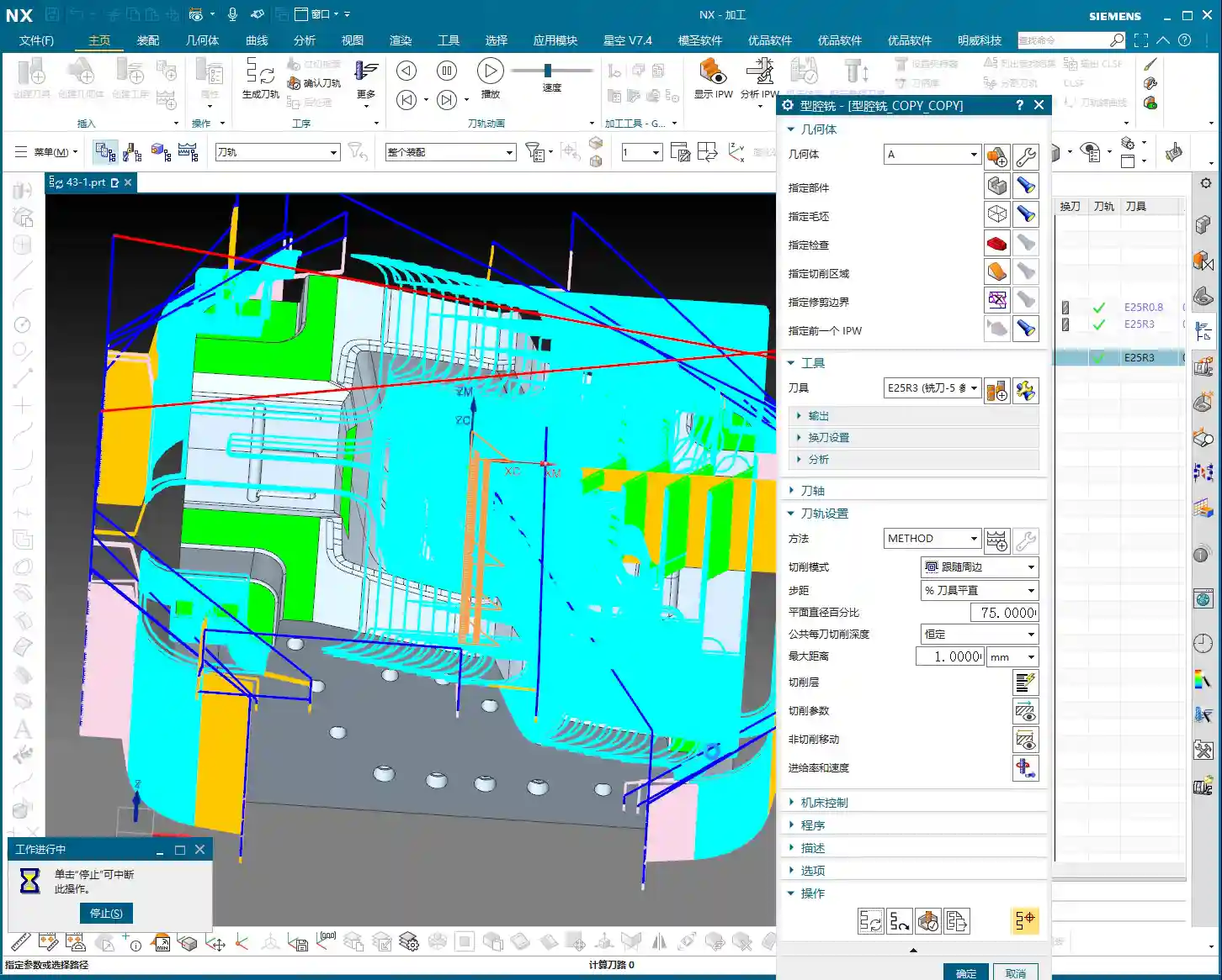
    Listen up, what exactly are machining layers? Simply put, it’s how you tell the machine where the tool should start cutting material in the Z-axis direction and where to stop. It’s not just a single cut from top to bottom; instead, it breaks down the entire machining depth into multiple layers. Especially when milling cavities, which can be quite deep, if you blindly try to “get it all done in one go,” your tool certainly won’t be happy.

    Let’s take roughing as an example. If a cavity needs to be machined from the top of the raw stock to a certain depth, and you don’t set up the machining layers properly, or if your settings are unreasonable, the tool might have to struggle to cut all the way down in a single pass. Never mind if the tool can handle it; even the workpiece itself might deform due to excessive cutting forces and poor heat dissipation. What we need to do is use machining layers to break down large jobs into smaller ones, and tackle tough material in smaller chunks.

    Machining Layer Definition and Practical Tips in NX

    In NX, there might seem to be many parameters here, but we’ll focus on the essentials. Once you understand a few core options, you can get to work.

    Setting the Top and Bottom Faces

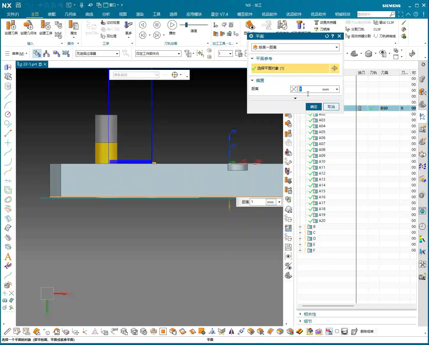
    For cavity milling, you first need to tell the software where to start cutting the “cavity” and where to finish. These are the Top and Bottom faces. We can either graphically select a face on the model or directly input a Z-axis coordinate value.

    • Top Face: This is typically the top face of the raw stock, or the surface machined in the previous operation. In NX, you can select a face or a point; it will use your chosen reference face or point as the highest machining point.
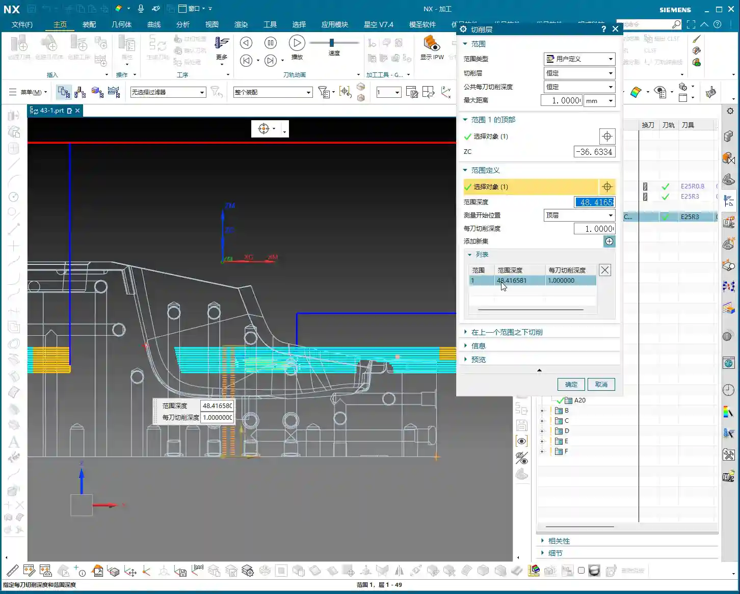
    • Bottom Face: Listen up, this is where mistakes often happen! The bottom face is the final depth you intend to machine in this operation. Newcomers often just click the absolute bottom face of the model in the graphics area and think they’re done. That’s not always the case! If you’re in “User Defined” mode and only select the top and bottom faces, NX might generate a “single layer” toolpath directly from the top to the bottom! For deep cavities, this can lead to serious problems.

    Master Wang’s personal emphasis: When setting the bottom face, it’s best to open the machining layer list and precisely select the last layer (plane) you want to machine to. That’s the safest approach!

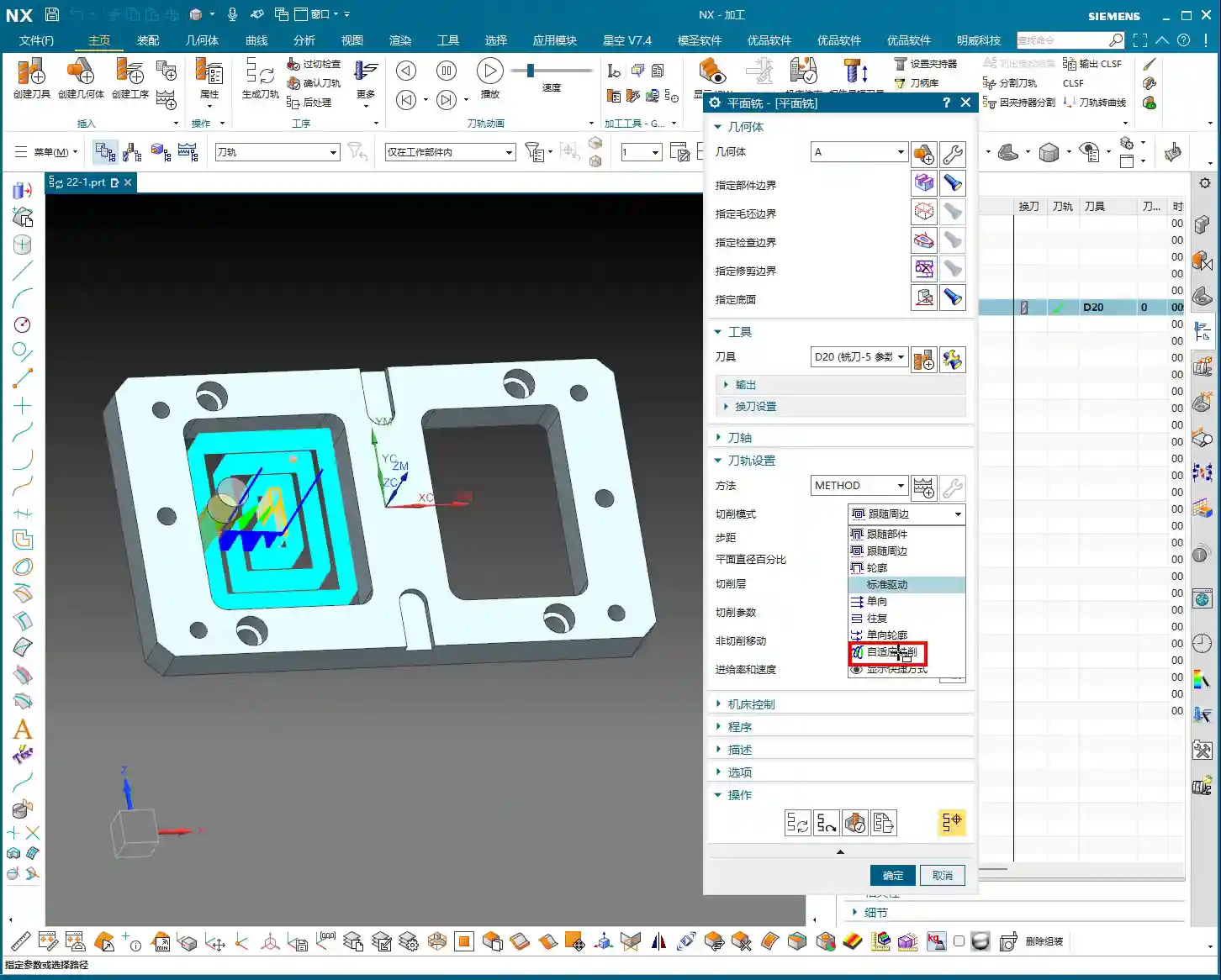
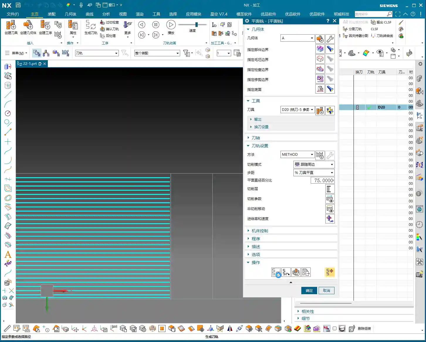
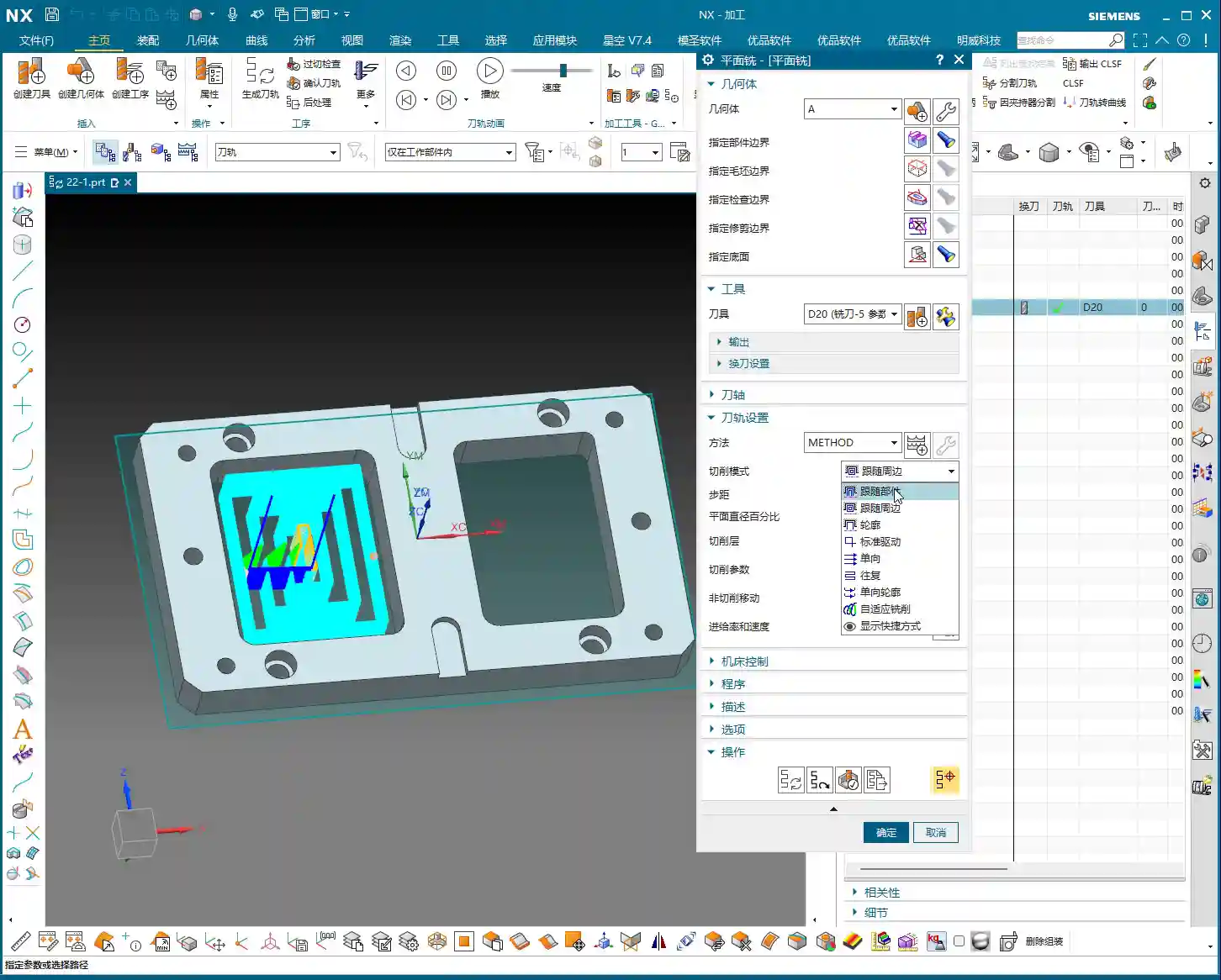
    Choosing Between “Automatic” and “User Defined” Modes

    This is central to machining layer settings and directly determines the toolpath layering strategy.

    • Automatic:

      This is NX’s more “intelligent” mode. When you select “Automatic,” NX will automatically identify all valid planes within your selected machining area and treat them as machining layers. For example, if your cavity has several steps or the top faces of some bosses, NX will recognize them and create machining layers on these planes. This allows the tool to better follow the actual geometry of the workpiece, avoid air cuts, and more intelligently distribute the Depth of Cut. This mode is suitable for roughing cavities with numerous geometric features.

    • User Defined:

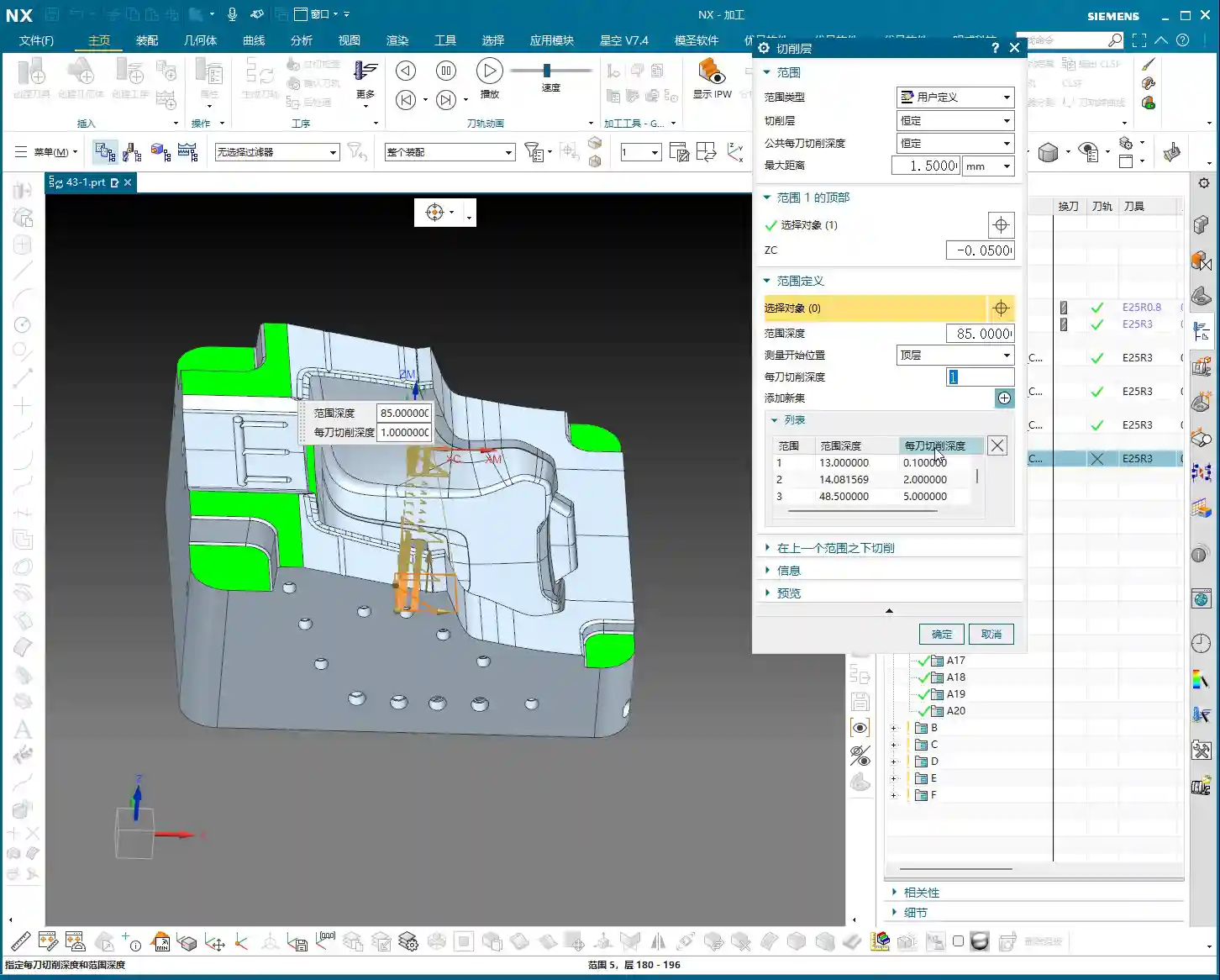
      This mode treats you like an experienced operator, giving you more control, but also meaning you bear more responsibility. Under “User Defined,” you can manually add (Add New Level) each machining layer. You can specify where the first layer is, where the last layer is, how many layers to add in between, and how large each layer’s interval should be – you have full control.

      For example, if you want the first Depth of Cut to be 10mm, the second 5mm, and the third 2mm, you can achieve this by manually adding different “levels.” But if you only select the top and bottom faces without manually adding intermediate machining layers, the software will assume you want to cut all the way down in a single pass! This is no joke; many newcomers fall into this trap, breaking tools and scrapping workpieces before realizing their mistake.

    Why So Many Machining Layers? — Practical Know-How Not Found in Textbooks

    Do some of you think, “Can’t I just set a top face, a bottom face, and a stepdown, and be done with it?” Why bother with so many layers and make it so complicated? That’s the difference between experience and theory. Let me break down the real essence for you:

    1. Control Tool Load, Extend Tool Life:

      This is the most crucial point! If a deep cavity is machined in only one layer, the tool has to remove a massive volume of material in a single pass, causing cutting forces to surge instantly. At best, this leads to accelerated tool wear and chipping; at worst, it causes tool breakage, or even damage to the machine spindle. Especially when machining “tough nuts” like titanium alloys and high-temperature nickel-based alloys, controlling tool load is paramount. Layered cutting effectively distributes the cutting forces, allowing the tool to “nibble away” at the material, significantly extending tool life. That’s a tangible cost saving!

    2. Precise Stock Control, Improved Machining Accuracy:

      Layered cutting allows for better control over the remaining stock in each layer. For example, in roughing, you might want to leave a uniform 0.5mm of stock on each layer to be removed during finishing. If the layering is unreasonable, some areas might have excessive stock, leading to heavy depths of cut during finishing, which impacts accuracy and surface quality.

    3. Effective Heat Dissipation, Prevent Workpiece Deformation:

      Large feed rates and deep cuts generate significant cutting heat. If too much heat accumulates, workpieces, especially thin-walled or high-precision parts, can easily experience thermal deformation. Layered cutting, combined with coolant, allows cutting heat to dissipate effectively, reducing the risk of workpiece deformation. When dealing with certain precision parts, I’d rather take several shallow cuts to minimize the risk of deformation.

    4. Avoid Air Cuts, Improve Machining Efficiency:

      In “Automatic” mode, the multiple machining layers identified by NX often correspond to internal geometric features of the cavity (e.g., steps, islands). This allows the tool to engage material only when necessary, reducing air cutting time and indirectly boosting overall machining efficiency.

    5. Optimize Surface Finish:

      During semi-finishing or finishing operations, we can achieve a better surface roughness by setting denser machining layers (smaller stepdowns). This is similar to polishing; gradually grinding layer by layer is what yields a mirror-like finish.

    Summary: Pitfall Avoidance Guide

    • Don’t Just Look at the Model, Check the List: When setting the top, bottom, or any intermediate layer, especially in “User Defined” mode, always open the machining layer list to confirm you’ve selected the exact plane or Z-value you intend, rather than just clicking randomly in the graphics area and assuming it’s correct.
    • “User Defined” is Not a Panacea: If you select “User Defined” mode but only specify the top and bottom faces, NX will, by default, generate a single toolpath, effectively cutting all the way down in one pass. For deep cavities, this is almost a “tool breakage trap”! Unless you are absolutely sure only one layer is needed.
    • Set Stepdown (Depth of Cut) Appropriately: The distance between machining layers is the stepdown. This needs to be determined based on a comprehensive consideration of tool diameter, material hardness, machine rigidity, and your desired machining efficiency and surface quality. There’s no one-size-fits-all parameter. Experiment, observe the cutting sparks and sound, and accumulate experience.
    • Stock Control is a Major Discipline: The Depth of Cut for each layer must account for leaving a reasonable amount of stock for the next operation. Especially the stock on the bottom and sidewalls; it needs to be left uniformly so that the finishing pass can proceed smoothly.
    • Learn to Use “Add New Level”: In “User Defined” mode, if you want to manually control the depth and number of each layer, you must learn to repeatedly use the “Add New Level” function to manually add each layer. While it might be a bit more work, it allows for the most precise control.

    Alright, that’s it for today on NX Cavity Milling machining layers. Remember, software is just a tool; the underlying machining principles and practical experience are your real bread and butter. Practice more, observe more, think more, and you too can become a master craftsman!

    👤 About the Author:
    The author is a veteran CNC machining professional with 15 years of industry experience, specializing in UG NX programming. This article is an original work representing personal practical insights.

    ⚠️ Copyright Notice: Unauthorized reproduction or distribution without prior communication is strictly prohibited.

  • Siemens NX Planar Milling in Practice: Master Wang’s In-Depth Analysis of Depth of Cut & Machining S

    📝 Key Takeaways:

    Deep Dive into Planar Milling Core Parameters

    Hello everyone, I’m Master Wang. Today, we’re diving back into the world of Planar Milling…

    Hello everyone, I’m Master Wang. Today, we’re diving back into the world of Planar Milling in Siemens NX, specifically focusing on the main interface and Depth of Cut settings. These are critical parameters that directly impact machining quality and efficiency.

    Siemens NX Planar Milling Fundamentals: Boundary Selection and Machining Depth

    Listen up. For planar milling, the first step is Boundary Selection. You can’t mess this up. Whatever you select, that’s what it will machine. Don’t get distracted by the fancy software interface; the core logic is that simple.

    Key Point: Closed Boundaries and Specify Bottom

    When you’re doing planar milling, remember this ironclad rule: you must select a closed boundary. What does “closed” mean? It means all sides are sealed off, like a complete frame, a solid shape. If you select an open line segment, the software won’t recognize it, and you won’t be able to machine anything. This isn’t a joke; it’s practical experience. Don’t make rookie mistakes here.

    Now, let’s talk about the Specify Bottom parameter. This is a critical setting, as it determines the depth your tool will mill to. For example, if you specify a bottom face, the tool will typically machine down to that surface. However, in real-world operations, you can’t be dogmatic about it.

    Depth Control: Depth of Cut and Stock Adjustment

    Let me ask you, if a part needs to be milled through, do you just specify the bottom face as the very bottom of the part? Young engineers often do this. But the reality is, machines have tolerances, and tools wear down. What looks “just right” in simulation software often ends up being “just short” on the actual workpiece.

    So, here’s a trick I’ll teach you: If the part needs to be milled through (perforated), you typically need to add an offset of 1 to 2 millimeters (approx. 0.04 to 0.08 inch) downwards from the specified bottom face. For instance, if the bottom face is at Z0, you’d input “-1” or “-2”. This ensures a 100% through-cut and avoids rework.

    Conversely, if there’s a fixture or features you don’t want to touch beneath the bottom face, then you cannot over-mill downwards. In such cases, you can add an upward offset (a positive value) to the specified bottom face, such as “0.2” or “-0.2” (depending on your NX version, the sign might be reversed, but the goal is to raise the toolpath). This creates a safety margin, preventing tool collisions or machining unintended areas. Want to see the actual toolpath position? Right-click the toolpath, select “Face Analysis,” and you’ll see the toolpath’s distance relative to the face. This face analysis stuff has been covered in your modeling classes; review it regularly, don’t wait until you’re in a bind.

    Toolpath and Cut Pattern: Practical Choices for Siemens NX Planar Milling

    Tool selection? Nothing much to say here. Just pick one based on your workpiece material and requirements. Use whatever’s in your tool library; if there’s no suitable one, grind a custom tool yourself.

    Tool and Tool Axis: Default Selection for 3-Axis Machining

    Regarding the Tool Axis, for standard 3-axis machining, the default is always the Z-Axis. Don’t blindly change it unless you’re doing 5-axis work. Parameters like “Method” are the same; I’ve covered them many times before. For most situations, keep them at their default settings and don’t worry about them.

    Cut Pattern: The “Roughing” Philosophy of Planar Milling

    Now, for the Cut Pattern – this is the core strategy for planar milling. While Siemens NX offers a ton of patterns like “Support Type Machining” or “Standard Drive,” honestly, for planar milling, we primarily use just a few:

    • Follow Periphery: The toolpath follows the part’s outer shape, spiraling inwards or outwards layer by layer. The visual effect and machining trajectory are quite clean, which is why I highly recommend it.
    • Follow Part: Similar to Follow Periphery, but sometimes the path can differ slightly. Actual machining results are also good.
    • Zigzag: The tool cuts back and forth in straight lines. Suitable for fast roughing of large flat surfaces, highly efficient, but prone to leaving tool marks at corners.
    • One-Way: Cuts only in one direction, lifting the tool on the return pass. This ensures even tool loading but involves more retracts, leading to relatively lower efficiency.
    • Profile: Pay special attention to this one. Profile mode only machines boundary lines, meaning the sidewalls, and does not machine the planar area itself. If you select “Profile” in a planar milling operation and find that the flat surface isn’t machined, don’t come asking me why – it’s because you haven’t understood the purpose of different modes.

    Master Wang tells you straight: in Siemens NX planar milling operations, we treat it as a “Roughing” tool. This means its primary purpose is to quickly remove large amounts of material. For this, Follow Periphery and Follow Part are the most reliable and commonly used options. If you want to “finish” the sidewalls (i.e., a finishing pass on the sidewalls), then don’t use the “Profile” mode within planar milling. Soon, we’ll learn about dedicated Planar Profile Milling, which is the professional way to finish sidewalls.

    Stepover: Balancing Efficiency in Lateral Cutting

    The Stepover parameter refers to the distance between the tool’s centerlines during each lateral movement. Siemens NX defaults to 75% of the tool diameter, which is a reasonable value for most situations. Too large, and you risk leaving steps; too small, and you’re just wasting time. You can adjust this flexibly based on the workpiece’s precision requirements, material hardness, and tool strength. However, there’s no absolute percentage for this; you’ll need to rely on experience and test cuts to find the optimal value.

    Core Parameters: Depth of Cut and Strategy

    Depth per Cut: The Trade-off Between Speed and Precision

    Finally, let’s talk about the Depth of Cut (DOC), specifically the Depth per cut. This value determines how much material you remove with each pass. Siemens NX might default to 1 millimeter (approx. 0.04 inch), but this entirely depends on your actual machining requirements and material. For instance, if you change it to 0.1 millimeter (approx. 0.004 inch), the toolpath will be very dense, increasing the number of cuts and improving surface finish, but the machining time will skyrocket. If you change it to 10 millimeters (approx. 0.4 inch), then naturally, each pass will take 10 mm, which is highly efficient, but it places much higher demands on machine rigidity and tool strength.

    This parameter is essentially the same as “Depth per cut” we covered in “Deep Bottom Base (DBB)” operations; the core concept is Depth of Cut (DOC). How much should you set it to? That depends on material properties, machine power, and tool material and strength. For aluminum, you can take deeper cuts. But for materials like titanium alloys or high-temperature nickel-based alloys, dare to take a deep cut? At best, you’ll break the tool; at worst, you’ll scrap the workpiece and have nowhere to vent your frustration. So, in such cases, you must reduce this value.

    To change it, go to the Depth of Cut parameters, find “Common”, and directly input your desired depth.

    In-Depth Analysis: “Finish Bottom” and “Constant” Modes

    Within the Depth of Cut settings, there are two modes you need to understand clearly:

    • Finish Bottom: This mode means “one cut to the bottom”. In other words, regardless of your set Depth per cut, it will make a single pass directly down to your specified bottom face. This is typically used for the final finishing pass or when high bottom surface precision is required with minimal stock remaining.
    • Constant: As the name implies, this mode proceeds layer by layer, following your set Depth per cut until it reaches the specified bottom face. This is the most common roughing mode, as it allows control over each layer’s material removal, ensuring machining stability and tool life.

    Simple enough, right? “Finish Bottom” is a clean single pass to the final depth, while “Constant” is a methodical, layered approach to cutting. Combining these two modes will cover most of your planar milling needs. Don’t overthink it; often, the simpler things are the most practical.

    Summary: Pitfall Guide

    That concludes our discussion on the planar milling main page and Depth of Cut settings for today. Remember these core points:

    • A closed boundary is the lifeline for planar milling; select it incorrectly, and you won’t be able to machine.
    • Specify Bottom must be used flexibly; apply an offset when needed. Especially for through-cuts, add an extra 1-2 millimeters (approx. 0.04-0.08 inch), and if there’s a fixture below, raise the toolpath.
    • Planar milling is primarily for roughing; the preferred cut patterns are “Follow Periphery” or “Follow Part”. For finishing sidewalls, use Planar Profile Milling.
    • Stepover and Depth per cut must be adjusted based on material and machine performance. There’s no absolute value, only the most suitable one. For hard or brittle materials, it’s better to take shallower, more passes to save both the tool and the part.
    • “Finish Bottom” is a single pass to the final depth, while “Constant” is a layered approach; choose according to your needs.

    As for feed rates, spindle speeds, rapid moves, and all that – I’ve lectured on those countless times before. Click into them yourself, and if you don’t understand, just experiment a few more times. With Siemens NX, you’ll only truly master it through practice, exploration, and comparing toolpaths generated by different parameter settings. Don’t just stick to theory; you need to observe the cutting sparks and listen to the cutting sound – that’s where the real skill lies!

    Next class, we’ll compare the cutting parameters across different machining operations to see which ones are common and which are unique, to deepen your understanding. There are no shortcuts here; it’s all about hands-on practice and critical thinking!

    👤 About the Author:
    The author is a veteran CNC machining professional with 15 years of industry experience, specializing in UG NX programming. This article is an original work representing personal practical insights.

    ⚠️ Copyright Notice: Unauthorized reproduction or distribution without prior communication is strictly prohibited.