Tag: Dynamic Milling

  • Siemens NX Secondary Dynamic Milling In-depth Analysis: Stock Inheritance Mechanism, Toolpath Optimi

    📝 Key Takeaways: Master Wang guides you through practical Siemens NX Secondary Dynamic Milling, unveiling the “stock inheritance” mechanism. Gain in-depth understanding of how 3D machining impacts toolpaths, and learn to adjust operation sequences to avoid common “red alarm” errors. Master the trick of setting Minimum Stock Removal to optimize cutting efficiency. This guide emphasizes when to use Workpiece vs. “A” mode, eliminating confusion, ensuring precise and efficient machining, and reducing costs!

    Foreword: Master Wang on Dynamic Milling

    Alright lads, today we’re talking about “Secondary Dynamic Milling” in Siemens NX, also known as “Secondary Roughing.” At its core, this is the same beast as the regular Dynamic Milling we’ve discussed before. Both use a 3D approach to clear out corners and residual material. Don’t let the complex name fool you; once you grasp the principle, it’s straightforward to operate. If you’ve mastered regular Dynamic Milling, Secondary Dynamic Milling will come naturally.

    The “Stock Inheritance” Mechanism in Siemens NX

    Listen up, this section is critically important. Textbooks might not cover it in such detail; this is all hard-won experience from real-world pitfalls.

    Problem Revealed: Has the Stock “Been Machined”?

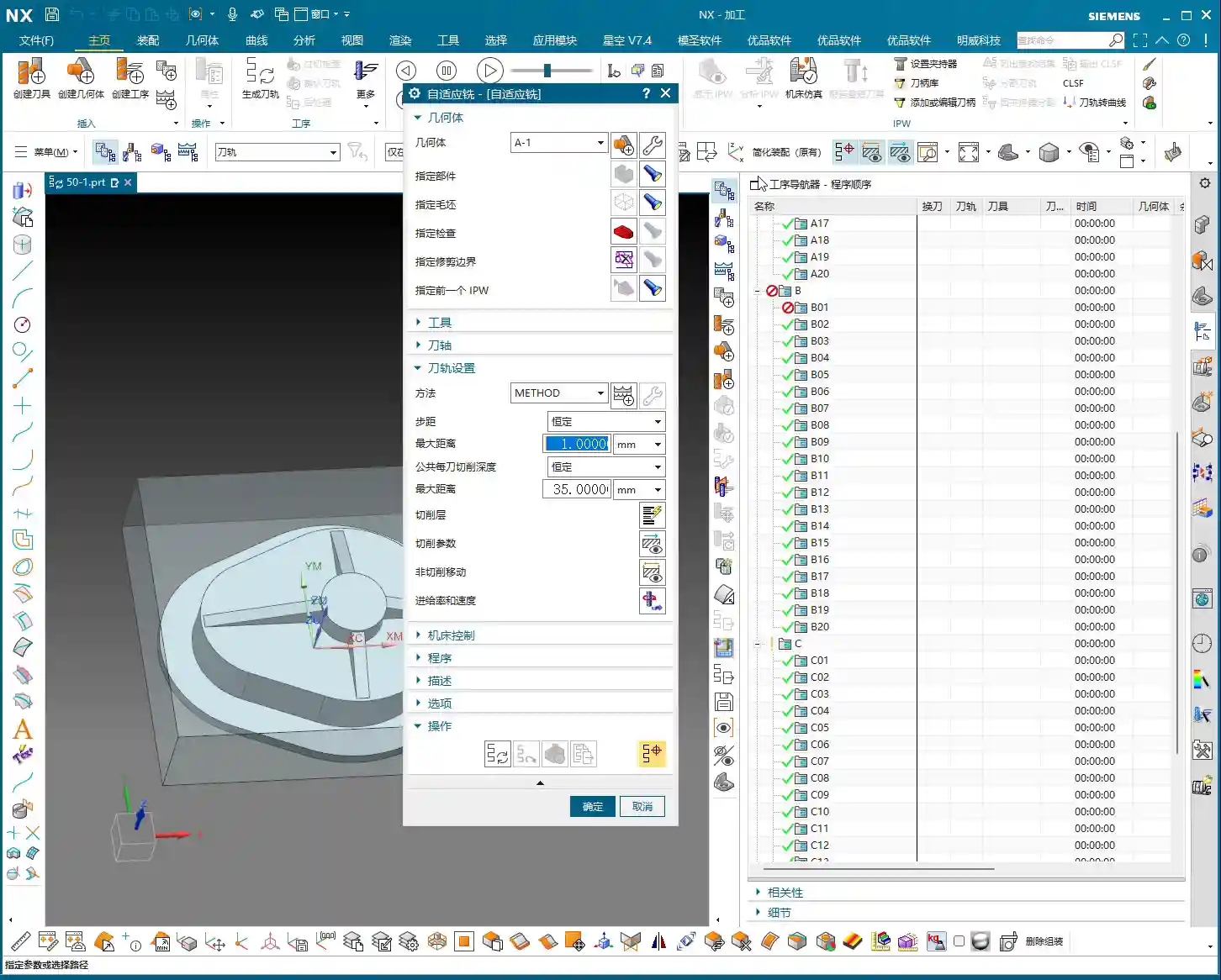
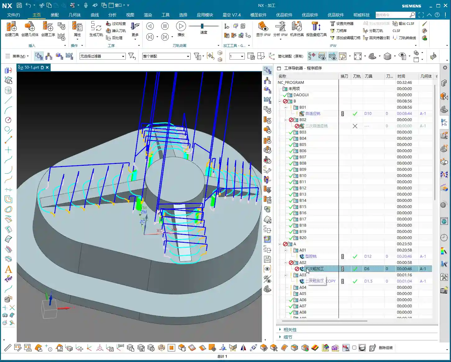
    Have you ever encountered this situation: it’s clearly a secondary roughing operation, but when you look at the Workpiece, it appears as if it’s already been machined, with all the edges nearly gone? This isn’t the software glitching out; it’s the fault of “inheritance”! Just as Master Wang demonstrated in the audio, if you select a A-1 Dynamic Milling operation, the Workpiece looks like it’s already finished – that’s not right.

    This is because Siemens NX, by default, will treat the machining result of the previous operation as the “stock” for your current operation. If that “previous operation” you’re referencing has already machined the part completely, then your secondary roughing operation will naturally have nothing left to do.

    Root Cause: Inheritance Relationships Between Operations (Workpiece)

    The Workpiece we select under “Geometry” isn’t a static entity; it has “memory.” Especially when you select “Use 3D,” it will faithfully read the residual stock after the previous referenced operation. This “Use 3D” option tells the software that you want to perform precise 3D residual stock calculations, not just a simple 2D contour determination.

    If your Dynamic Milling operation is placed after the roughing operation, it will inherit the stock remaining after the roughing pass. If the roughing hasn’t been defined correctly, or is defined incorrectly, or even hasn’t been machined yet, then this Dynamic Milling operation might have nothing to machine or might machine the wrong areas. As mentioned in the audio, if the preceding operation also used 3D, then the subsequent operation inherits its machining result, layer upon layer, just like Russian nesting dolls.

    Pay attention, this is important: If your operation uses Workpiece and has “Use 3D” checked, then its calculation is based on the final machining state of all preceding operations that also used Workpiece and “Use 3D.”

    Solution: Operation Sequencing and “A” Mode

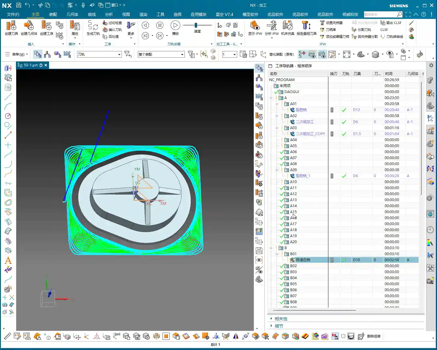
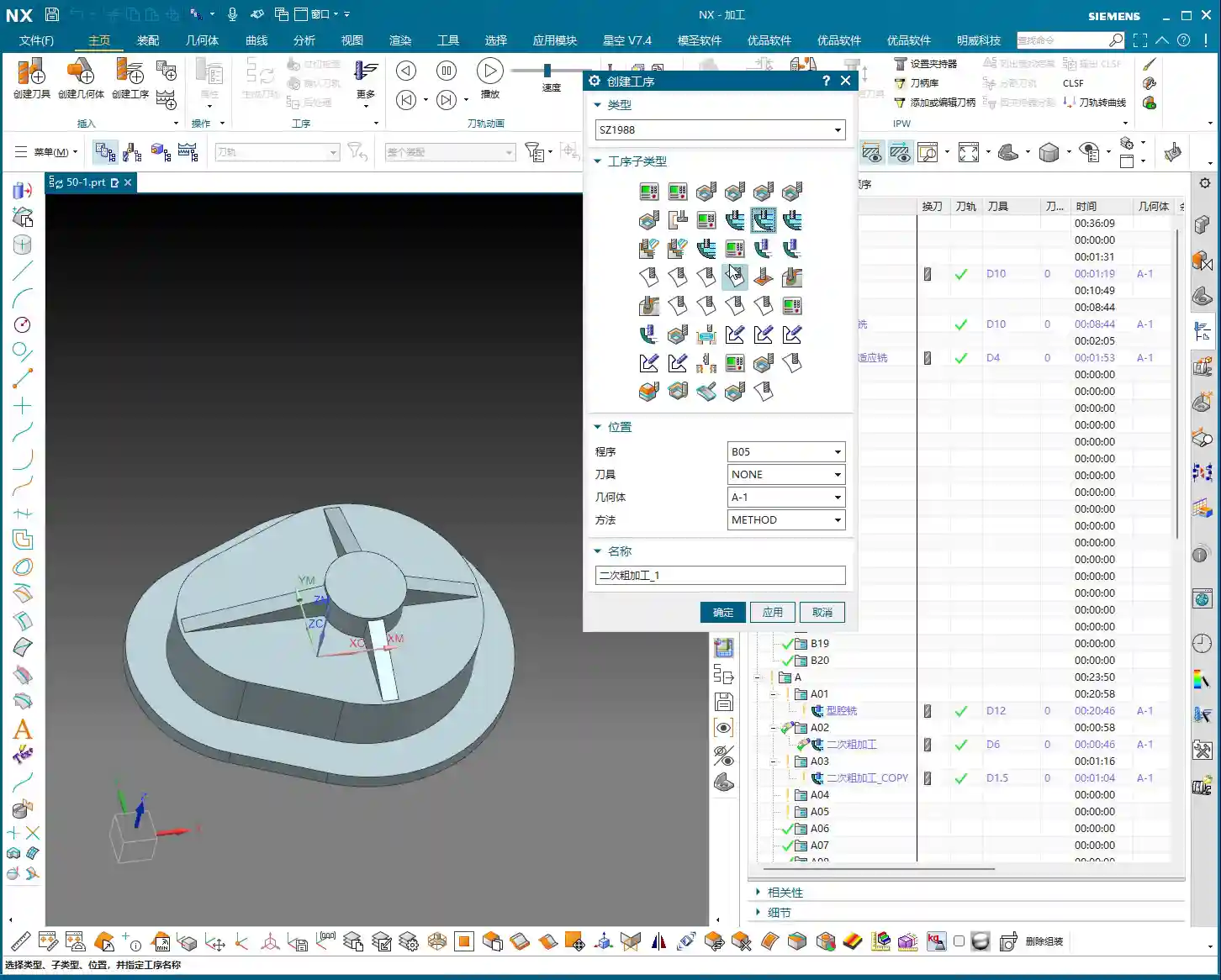
    When the stock seems incorrect and the operation turns red (error), your first reaction should be to check your operation sequence! Arrange operations with clear inheritance relationships, such as roughing and secondary roughing, according to the actual machining sequence. Just as Master Wang demonstrated in the audio, move the roughing and dynamic milling operations to the front so they machine the original stock first. This way, subsequent operations will correctly inherit their machined state, the operations won’t turn “red,” and a simple “generate” will pass them.

    Master Wang’s Pro Tip: For beginners, if you’re unclear about the “Workpiece” inheritance relationship, **just avoid using Workpiece altogether; directly select “A.”** Selecting “A” means you’re telling the software that this operation is targeting the entire geometric model of your part. As for the stock, we manually define the machining area or control it via toolpath. This can prevent many unnecessary issues and “red alarms.” Since you’re not using 3D for stock calculation, it won’t inherit the machining state of preceding operations; it will only recognize your currently defined machining region. This is a “lazy” yet effective method to avoid detours!

    Practical Parameter Settings for Secondary Dynamic Milling

    Theory’s done; now let’s get practical and see how to adjust the parameters. These are the optimal configurations I’ve refined over many years; just use them as is.

    Tool Selection and Stepdown: The Power of Templates

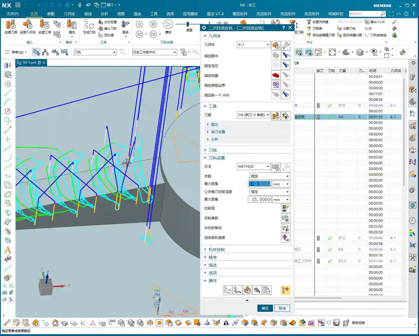
    For tool selection, it depends on the actual situation, for example, using a D4 end mill. I, Master Wang, typically use templates, so many parameters are ready to go with a click. For instance, the Stepdown (Depth of Cut), we usually set it to around 0.5mm (approx. 0.02 inch), depending on the material and tool conditions. Other connection parameters and the like usually don’t need changing if you’re using a template.

    Why use templates? Efficiency! Who has time to set everything from scratch every time? Consolidate common parameters, and you save effort, time, and reduce errors. This is a crucial step for improving your efficiency in the future and the cornerstone of standardized production.

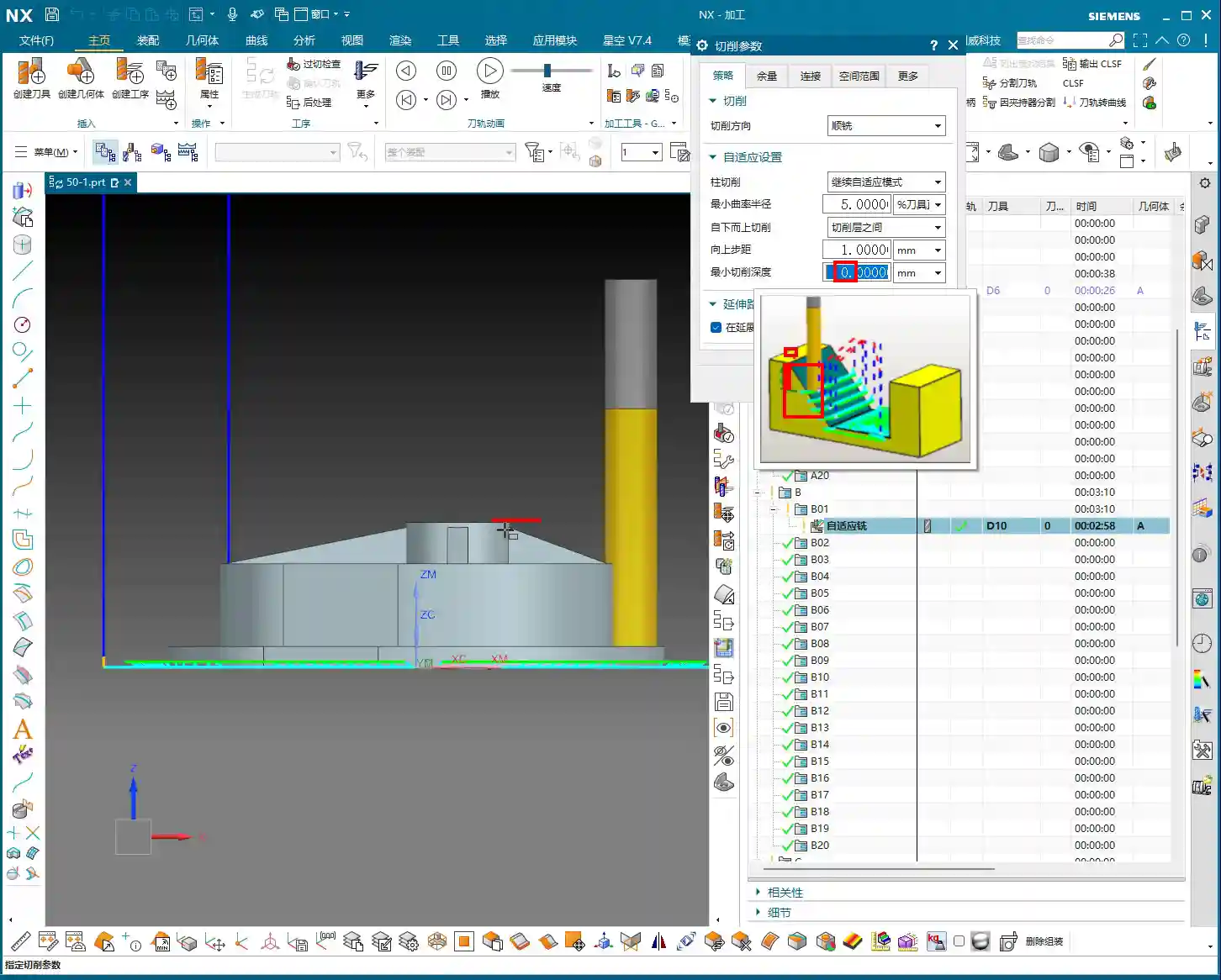
    Key Parameter: Minimum Stock Removal

    This parameter, “Minimum Stock Removal,” listen very carefully, is the key to Dynamic Milling efficiency!

    Its purpose is to tell the software not to machine an area if the remaining stock is less than this value. In the audio, Master Wang suggests setting it to 0.5mm (approx. 0.02 inch). Why?

    • Consider this: if you set it too small, for example, 0.01mm (approx. 0.0004 inch), the software will relentlessly calculate and try to remove material in areas with almost no stock. This will generate an excessive number of toolpaths, leading to calculation times that will make you question your life choices.
    • Furthermore, the actual machining effect won’t improve much, and efficiency might even decrease due to too many air cuts.
    • Therefore, setting it to 0.5mm (approx. 0.02 inch) ensures most residual material is removed while avoiding unnecessary calculations and cutting. This is based on experience and represents a balance between cost and efficiency. You can’t justify tying up the machine and tool for such a tiny, negligible amount of stock, can you?

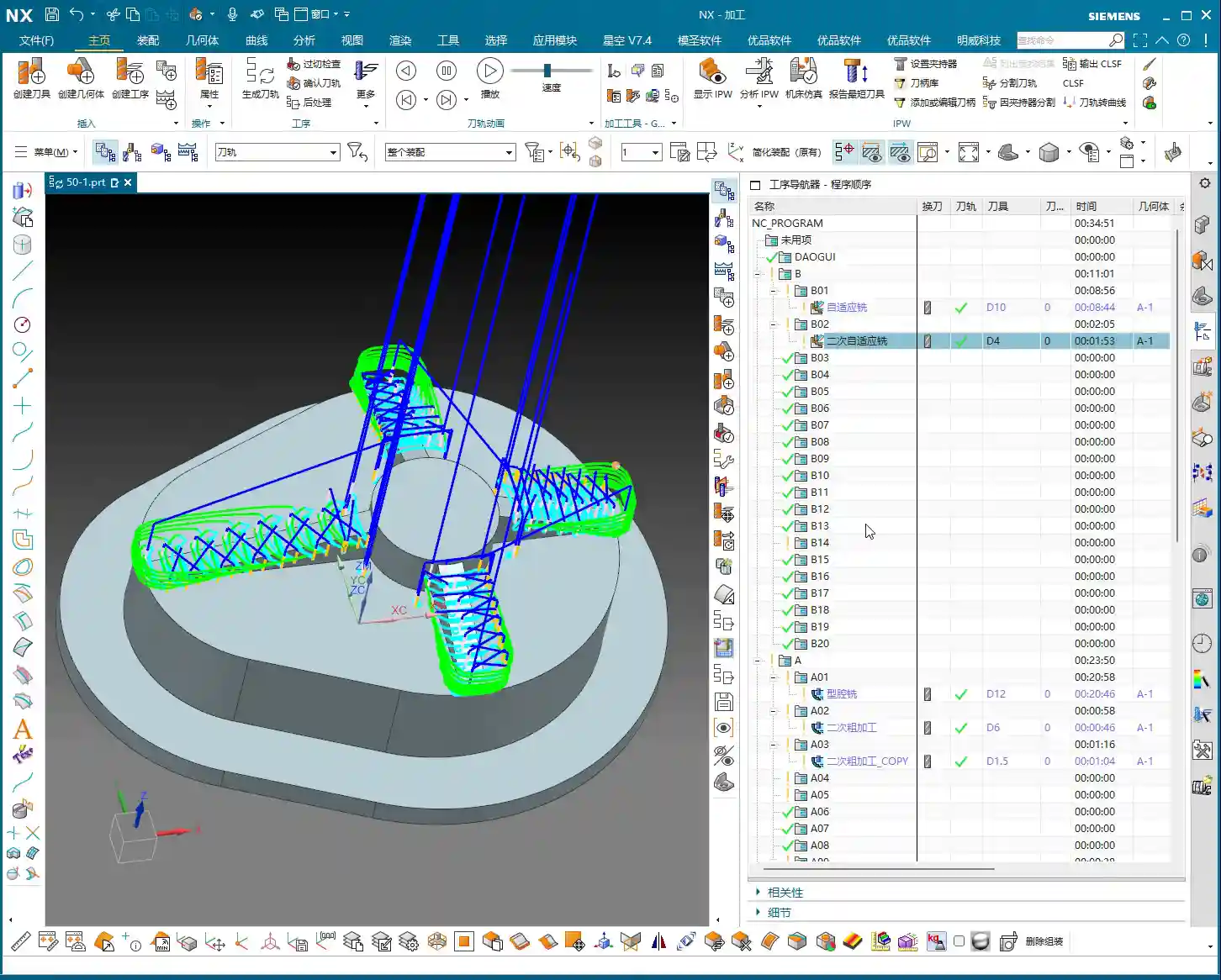
    Toolpath Generation and Simulation: Efficiency and Observation

    Don’t just watch the software run; you need to understand what’s happening behind the scenes.

    Time-Consuming Nature of 3D Calculation

    3D machining in Siemens NX, especially dynamic milling that requires precise residual stock calculation (particularly when you have “Use 3D” checked), will take a comparatively longer time to calculate, and this is normal. That’s because the software has to analyze the entire 3D model, calculate the stock at every point, and then plan the toolpaths – this is far more complex than simple 2D operations.

    So, when calculations are slow, stay calm, grab a cup of tea, and don’t click around aimlessly. Patiently wait; a high-quality toolpath is worth it.

    Observing Cutting Sparks: Beyond Software Simulation

    Software simulation might look great, but it’s still just a simulation! When you’re on the machine later, keep your eyes on the cutting sparks and your ears on the cutting sound. If the sparks are too yellow or the sound is too dull, you might be experiencing excessive Depth of Cut; immediately reduce the feed rate. If the sparks are too bright or the sound is too crisp, it could indicate tool wear or parameters set too low. You need to combine all these observations to truly prevent tool wear and ensure machining quality.

    This is “real skill” that you won’t learn from textbooks; you have to gradually accumulate it yourself. Most of my fifteen years of experience, Master Wang, came from “seeing” and “listening” on the shop floor.

    Master Wang’s Secret: The “Golden Rules” of Siemens NX Programming

    Next are Master Wang’s “plain-talk” summaries for Siemens NX programming, simplifying those complex topics from before. These are your “golden rules” for future work.

    When to Use `Workpiece` and `Use 3D`

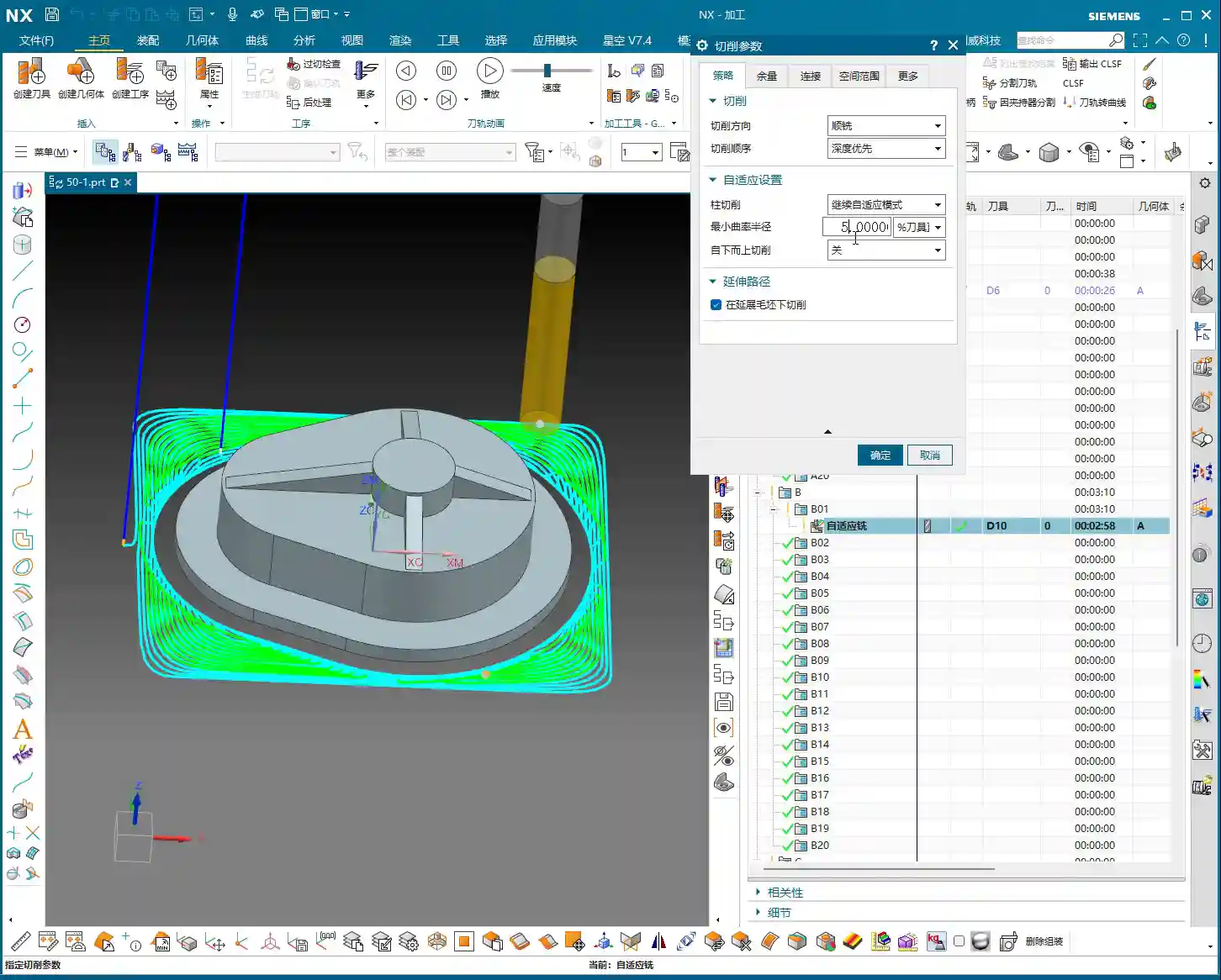
    Listen closely, the core principle is: If your operation needs to precisely calculate the residual stock based on the machining results of a preceding operation (e.g., secondary roughing after roughing, or secondary dynamic milling after cavity milling), then:

    • You must set “Geometry” to Workpiece and check “Use 3D” in your Roughing operations and all Dynamic Milling operations requiring this precise residual stock calculation.
    • Furthermore, their sequence in the operation navigator must be strictly correct, adhering to the actual machining process. Otherwise, you’ll get a flurry of “red alarms,” and you won’t know how to proceed.
    • The purpose of this setting is to enable the software to accurately “know” how much material remains to be cut. From roughing to semi-finishing, this progressive calculation of residual material is crucial for ensuring final accuracy and efficiency.

    Strategy for Non-3D Toolpaths: Revert to “A” Mode

    Aside from the 3D Dynamic Milling operations mentioned above that require precise residual stock calculation, for **all other operations, such as face milling, floor/wall milling, contour milling, etc.**, you should consistently set “Geometry” to “A.” Then, manually specify the part (the geometry to be machined) and manually specify the cutting region (the area for the toolpath to clear).

    The advantage of doing this is that operations no longer influence each other’s “stock” status. If you change the order of one operation, the others won’t turn red due to inheritance issues. This greatly simplifies your learning and troubleshooting, making programming much more controllable. For these non-3D machining modes, they don’t need to know precisely how much stock was removed in the previous step; they only need to know which face or region to machine.

    In the initial learning phase, this method will help you avoid many detours and the awkward situation of “everything turning red” with one change. Once you have enough experience and a thorough understanding of Siemens NX’s inheritance mechanism and 3D calculations, then it won’t be too late to experiment with more complex Workpiece management.

    Summary: Pitfall Avoidance Guide

    • Operation Sequence is Key: For operations involving “stock inheritance” (especially Workpiece operations with Use 3D enabled), ensure they are arranged according to the actual machining sequence, like an assembly line, step by step, without skipping.
    • Don’t Panic at “Red Alarms”: If an operation turns red, chances are it’s an inheritance issue. Check references and sequence, or if an operation that depends on prior machining has been moved too early.
    • Flexible Use of “A” Mode: For most standard machining operations, using “A” mode and manually defining the machining area can effectively avoid the complications of stock inheritance. This is the most reliable method for beginners.
    • Minimum Stock Removal Must Be Reasonable: Randomly setting it to 0.01mm (approx. 0.0004 inch) is a waste of resources! Set it to 0.5mm (approx. 0.02 inch) or even larger, based on actual needs, to balance efficiency and quality, and reduce calculation time.
    • Experience is the Best Teacher: Software is just a tool. Theory must be combined with practical operation. Observe more, think more, to truly become an expert. Don’t just stare at the screen; pay attention to the machine and analyze problems!

    👤 About the Author:
    The author is a veteran CNC machining professional with 15 years of industry experience, specializing in UG NX programming. This article is an original work representing personal practical insights.

    ⚠️ Copyright Notice: Unauthorized reproduction or distribution without prior communication is strictly prohibited.

  • Siemens NX Dynamic Milling Roughing in Practice: Master Wang’s Hands-on Guide to Cost Efficiency and

    📝 Key Takeaways: Master Wang reveals the essence of Siemens NX dynamic roughing, using efficient side milling, detailing key parameters like blank definition, stepover, and minimum depth of cut. Through practical examples, he shares hands-on techniques for single-pass cutting and smooth tool paths to boost your machining efficiency, avoid common errors, and achieve ±0.005mm accuracy.

    Hello everyone, I’m Master Wang. Today, we’re going to break down Dynamic Roughing in Siemens NX. This is a powerful technique; master it, and you’ll significantly boost your efficiency. I’ve got a good part here, so let’s use it as an example and walk through the whole process from start to finish.

    Dynamic Milling Basics: Efficient Side Milling

    Listen up. Dynamic milling, simply put, fully utilizes the tool’s side cutting edge for machining. Compared to traditional bottom-cutting, the side cutting edge experiences more uniform force, leading to higher cutting efficiency and less tool wear. So, don’t just focus on the tip of the tool; the side edge is your powerhouse for roughing.

    NX Module and Process Selection

    In NX, we directly open the 3-axis module, scroll down, and find Cavity Mill Secondary Roughing. You’re definitely familiar with this one. As for Rest Milling next to it, while the name is different, it’s essentially the same concept as Cavity Mill Secondary Roughing – both are for re-machining material remaining from a previous operation. NX simply assigned its own template name; no need to overthink it. So, if secondary roughing can handle the job, you can skip rest milling; there’s no need for an extra step.

    Today, we’re primarily focusing on Dynamic Roughing, which you’ll find further down in the module.

    Blank and Part Definition: The Foundation of Accuracy

    Defining the part and blank is the first, and most crucial, step in machining. Get this wrong, and no matter how fancy your tool path, it’s all for nothing.

    Selecting Part and Blank: Avoiding Detours

    Didn’t I already create the blank? Then just use it directly. Dynamic milling primarily relies on side milling, so often you don’t need to select an additional 3D model for secondary definition. Just use the current blank; it saves you time and effort.

    To select the Part, you’re choosing the final shape of the component you want to machine; to select the Blank, you’re specifying the raw material before any machining. This is basic stuff; anyone who’s operated a machine understands it.

    Blank Dimensions: Flexible Control is Key

    How do you define blank dimensions? The most common method is to control it with a Bounding Body. The size of your bounding body dictates the blank size. If you need more precise adjustments, after creating the bounding body, you can modify the blank’s volume using Offset or Replace. This offers greater flexibility and adapts to blanks of various irregular shapes.

    ABW and Program Association: The Crux of the Matter

    This ABW refers to program association. Initially, we might be tempted to select options like A-1, which means it will inherit the machining status from the previous program. But here’s where you can get into trouble, so listen carefully:

    If the part has already been roughed using Workpiece in a previous operation, and you then select A-1, the system will assume that material has already been removed. The result? You’ll mill nothing! The tool will just air cut or crash into existing material. This is a very common mistake for beginners, and even experienced operators can overlook it sometimes.

    Therefore, we must directly select A to make it independent, so it only recognizes the current blank and isn’t linked to the previous program. That’s how you play it safe! Remember, independence is critical; it effectively prevents machining errors caused by program association, especially during continuous multi-operation machining.

    Tool Path Parameter Fine-Tuning: Balancing Efficiency and Quality

    Setting dynamic milling parameters is key to determining machining efficiency and surface quality. Each parameter has its quirks; you need to understand them thoroughly.

    Stepover: The Golden Ratio for Side Milling

    This stepover is the lateral feed distance for each pass during side milling. For dynamic milling, an experienced value is typically set around 1 mm. Too large, and the tool experiences uneven forces, leading to chatter; too small, and you get too much air cutting, reducing efficiency. Adjust it slightly based on tool diameter and material hardness to find that sweet spot.

    With this machining method, it’s often a single-pass cut, so you can set the depth of cut quite high, even exceeding the total part height directly.

    Max Depth Per Cut: The Secret to Single-Pass Cutting

    My part’s total height is 28 mm. Here, I’ve set the Max Depth Per Cut to 35 mm. See, it only mills down to 28 mm in practice. Why? It’s simple: as long as the depth you set is greater than the total height of the part, it will make a single-pass cut without layered steps. This is a trick for boosting efficiency, eliminating frequent tool retracts. But this only works if your machine rigidity, tool strength, and cutting parameters can handle it; don’t force it.

    Cut Levels and Range: The Essence of Single-Layer Cutting

    You’ll notice that the Cut Levels here are empty, with no layers. That’s because we’ve set the Range to Single. The characteristic of dynamic milling is that by using the side cutting edge, you can achieve a very large depth of cut in one go. So, typically, setting it to a single cut level is sufficient; there’s no need for the layered progression seen in traditional milling. It’s simple and effective – that’s the principle.

    Minimum Curvature Radius: The Secret to Smooth Tool Paths

    Here, we have the Minimum Curvature Radius, which defaults to 5%. What’s this thing for? It allows your tool path to automatically generate arc transitions at corners. Don’t underestimate these few points; they make the tool path smoother, prevent impact during right-angle cutting, reduce tool wear, and extend tool life. The machined surface will also be cleaner, especially noticeable in high-speed machining. Generally, keeping the default is fine, unless you have specific requirements.

    Cut from Bottom to Top: Crucial for Sloped Surface Machining

    Why do some sloped surfaces only get machined at the bottom, leaving the top untouched? It’s because you haven’t selected Cut from Bottom to Top. By checking this option, the tool will start from the bottom and mill upwards along the slope, layer by layer. This is essential for complex sloped surfaces. Remember to also set the Upward Stepover, usually keeping it consistent with the horizontal stepover, for example, 1 mm. This ensures uniform tool paths and prevents overcutting or undercutting.

    Minimum Cut Depth: The Mystery of Stock Control

    This Minimum Cut Depth is an extremely critical parameter, so don’t get it wrong!

    • If you set it to 0: This means the tool tip will machine directly to your defined part surface, removing all material. During roughing, we typically set this to 0 to ensure maximum material removal.
    • If you set it to a positive value (e.g., 5 mm): The tool will then stop cutting 5 mm above the lowest point of the workpiece, leaving you with 5 mm of stock. For instance, if the workpiece’s lowest point is Z0, and you set it to 5, it will only cut up to Z5, leaving anything above Z5 untouched. This is useful when you need to leave uniform stock before finishing, but be careful when roughing, as it can easily leave excessive material.

    Understand what I mean? Don’t underestimate this single parameter; if you don’t grasp it, you might end up with incorrect stock, or worse, a tool crash and a scrapped part!

    Blank Distance: Considerations for Tool Path Integration

    Blank Distance – I’ve brought this up many times in previous lessons. The gap you set here is what the system uses to determine where there’s material to cut. If you set it too high, and the actual blank is still some distance from the tool, the system will assume there’s no material there and won’t cut, resulting in undercutting. Conversely, if set too small, it could lead to overcutting. So, you must set it according to the actual blank conditions and your cutting strategy; don’t just guess.

    Tool Path Generation and Simulation: Seeing is Believing

    Once all parameters are set, we can generate the tool path and then proceed with simulation for verification. Practice is the sole criterion for truth!

    Generating Tool Paths: The 1-2-3 Method for Quick Program Output

    Remember my 1-2-3 rule: Select tool, select geometry, select method. After setting the parameters, just click OK, and the program is immediately generated. This efficient workflow will save you a lot of time.

    3D Simulation: Gaining Insight into the Machining Process

    Once the tool path is generated, don’t rush to the machine. First, simulate it on the computer. Directly select the blank and use 3D simulation. A key feature of dynamic milling is that it starts cutting directly from the blank, unlike some programs where you first have to face off a bottom surface. Through simulation, you can clearly observe the tool’s movements, cutting trajectory, and the material removal process. See how the side cutting edge removes material layer by layer, and how slopes are machined from bottom to top, ensuring no overcutting, undercutting, or air cuts.

    See how clear this tool path is! That’s the entire dynamic roughing process – efficient and precise.

    Summary: Pitfall Avoidance Guide

    • Avoid Program Association Traps: When selecting the part/blank, if there are previous machining programs, always choose the independent A option, not inherited options like A-1. This prevents the system from misinterpreting already removed material and causing air cuts.
    • Stepover and Depth: For dynamic side milling, the stepover is typically 1 mm. The maximum depth per cut can be set greater than the total part height to achieve a single-pass cut, provided the machine and tool rigidity are sufficient, and cutting parameters are matched.
    • Minimum Cut Depth: During roughing, it must be set to 0 to ensure the tool cuts to the part surface and completely removes all stock. If you need to leave stock, understand its physical meaning relative to the lowest point.
    • Cut from Bottom to Top: For sloped surfaces, enable ‘Cut from Bottom to Top’ and set the upward stepover to ensure complete material removal and prevent undercutting.
    • Simulation Verification: After generating the tool path, always perform 3D simulation verification. Carefully observe the tool path to ensure there are no collisions, overcuts, undercuts, or air cuts. This is your last line of defense before going to the machine.

    Alright, that’s it for this lesson. These are all practical experiences I’ve gained over 15 years in the trenches; you won’t learn this from textbooks. Go back and really think about it. Next lesson, we’ll continue our discussion. Don’t fall behind!

    👤 About the Author:
    The author is a veteran CNC machining professional with 15 years of industry experience, specializing in UG NX programming. This article is an original work representing personal practical insights.

    ⚠️ Copyright Notice: Unauthorized reproduction or distribution without prior communication is strictly prohibited.