Siemens NX (UG) Operation Sheet for Setup A: Practical Deep Dive
…
[VIDEO_HERE]
Overview: The Importance and Core Function of the Operation Sheet
Listen up, folks! In mechanical machining, no matter how perfectly you program toolpaths in Siemens NX, if you can’t clearly convey that information to the shop floor operators, it’s all for nothing. The operation sheet, simply put, is the ‘interpreter’ and ‘guidebook’ connecting us programmers with the machine operators. It absolutely must clearly detail how to fixture the part, which face is up, what areas to machine in each step, what tools to use, and what precautions to take. Today, we’re going to start with the most fundamental and critical Setup A operation sheet, and I’ll walk you through how to generate it, and more importantly, how to interpret and effectively utilize it!
Step One: Select Programs for Output and Initial Verification
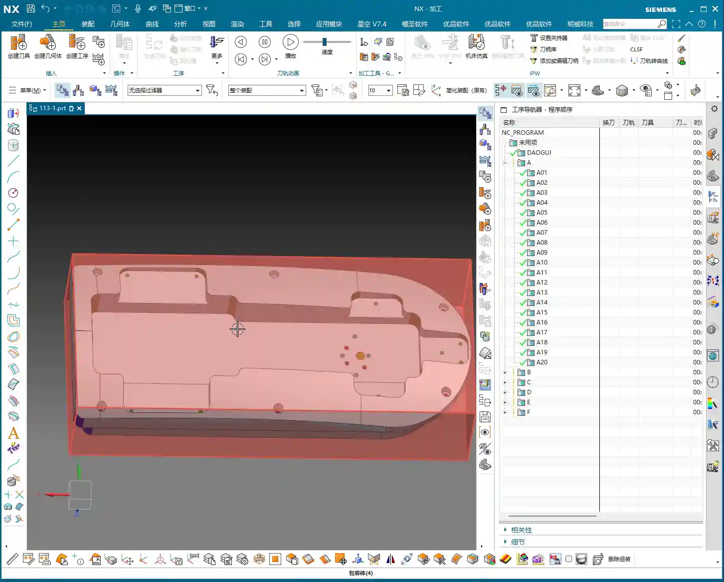
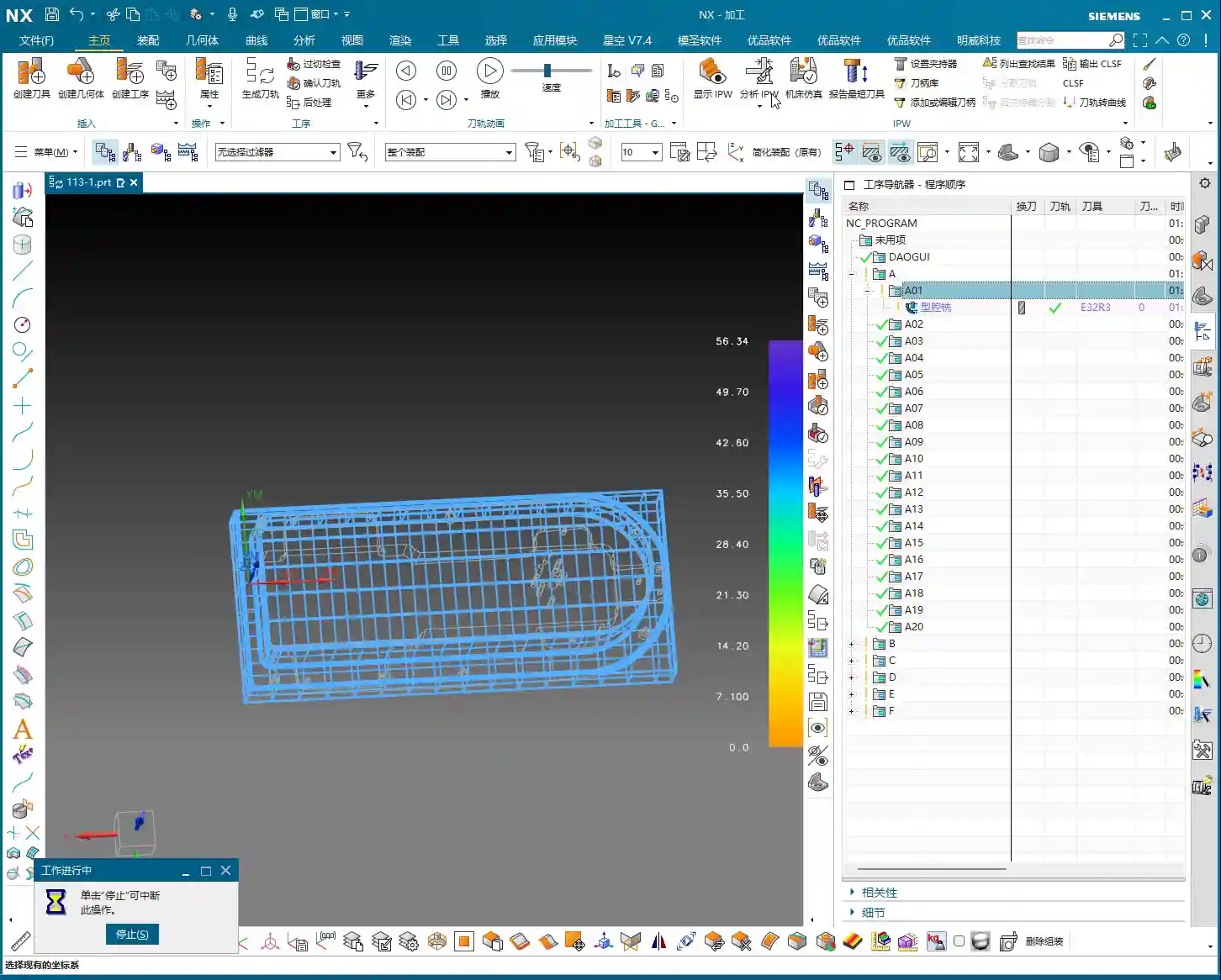
In Siemens NX, first, select all the toolpath programs you want to output an operation sheet for (e.g., A01, A02, A03 for Setup A). Once selected, here’s a good habit: always simulate the toolpaths first to ensure there are no issues and that the fixturing is appropriate.
For a part like this one, Setup A involves machining a single face. So, when clamping, you need to secure the part in a vise, exposing the face to be machined. Simulating it gives you a clear understanding. It also provides the operator with a visual machining preview, building confidence and reducing the chance of errors.
Step Two: Select the ‘Generic Operation Sheet’ Function
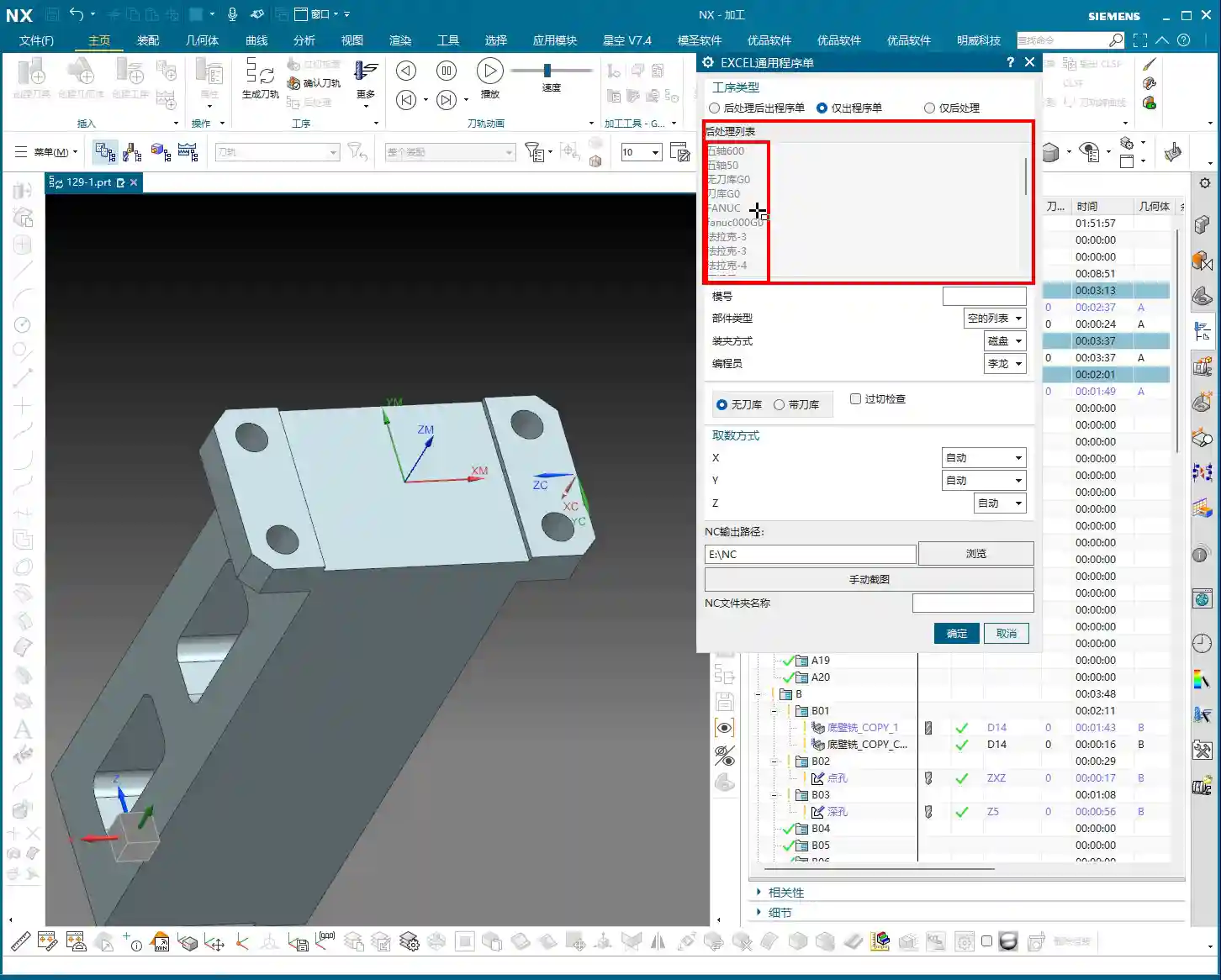
Toolpaths are good, programs are selected. Next, it’s time for the crucial step of outputting the operation sheet. In the Siemens NX menu, find the ‘Generic Operation Sheet’ option. For us, this is usually achieved through the ‘Starry Sky’ plugin. Just click it.
Step Three: Understand Output Options and Path Settings
Once open, you’ll see several output types:
‘Post-Process and Output Operation Sheet’: This means outputting both the G-code (post-processed file) and the operation sheet simultaneously.
‘Output Operation Sheet Only’: This outputs only the operation sheet; we can handle the G-code separately later.
‘Output Post-Process Only’: This outputs only the G-code.
Since we’re focusing on operation sheets today, select ‘Output Operation Sheet Only’. When you do, you’ll notice the ‘Post-Process List’ section is empty. That’s perfectly normal, just ignore it. As for the ‘Tables’ and other options below, those are more detailed settings we’ll cover later; you can safely disregard them for now.
Regarding the output path, many people just stick with the default. But listen up, I, Master Wang, have a personal habit: I typically create a dedicated ‘NC’ folder on my D: drive or another non-system drive, and I put all post-processed files and operation sheets in there. This makes management easier, finding files quicker, and prevents clutter. You might want to adopt this practice.
Step Four: Confirm and Generate the Operation Sheet
Once all previous settings are configured, just click ‘OK’. No need to mess with any other parameters; the operation sheet will be automatically generated and saved to your specified path.
In-Depth Interpretation of Key Information in the Setup A Operation Sheet
Part Basic Information and Datum Reference
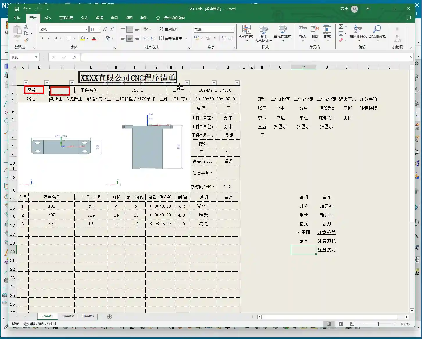
Dimensions: The operation sheet will clearly specify the part’s length, width, and height. For example, our part here is 100mm long, 50mm wide, and 182mm high. These are the final finish cut dimensions, so the operator knows the part’s size at a glance.
Locating Datum: This is critically important! The operation sheet will clearly state the tool offsetting method. For example, here it’s ‘Center X & Y, Top Face Zero’. This tells the operator exactly where the tool offsetting origin is for the X, Y, and Z axes – absolutely no room for error.
Views: The automatically generated XY and XZ views from Siemens NX provide a clear visual of the part’s machining faces and tool offsetting points. When operators see these diagrams, they’ll have a crystal-clear understanding of the features to be machined and the datum locations. Don’t just rely on software simulations; look for the cutting sparks! Drawings are merely aids; the shop floor is where reality happens.
Company and Workpiece Information
Mold/Job Number: This section can be filled according to your company’s specific requirements. If you want it to display the company name or a particular mold number, you can preset it in the operation sheet template. How do you modify the template? I’ve covered that in detail in my previous video tutorials; go check them out yourself – it’s fundamental!
Workpiece Name: For example, Programmer and Date
Prepared By: Here, I’ve put ‘Wang’. You can enter your own name or employee ID. This is also something you modify in the template; set it once, and it will auto-populate thereafter.
Date: The specific date and time the operation sheet was generated, such as
File Path and Dimension Verification
Path: The file path where the operation sheet is stored. While it might be long, the operator only needs to know which lesson’s folder (e.g., ‘Lesson 129’) it’s in to find the corresponding NC file. This helps our shop floor colleagues locate the correct file and prevents loading the wrong program.
Actual Dimensions: Emphasizing again: 100mm long, 50mm wide, and 182mm high. These are the final finish cut dimensions of the part.
Clamping Method and Precautions
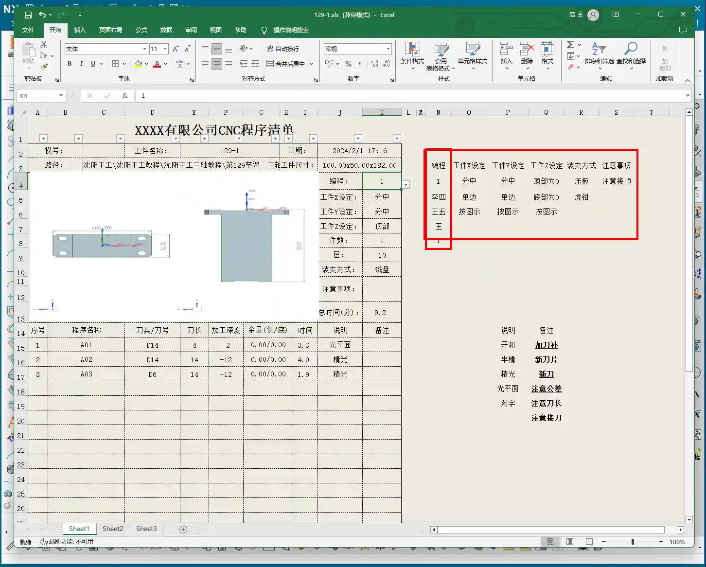
Clamping Method: For example, we’re using a ‘strap clamps’, ‘three-jaw chuck’, Precautions: For instance, Total Machining Time and Sequence Details
Total Time: The combined total machining time for all Setup A programs (A01, A02, A03), for example, Sequence Details: The operation sheet will list each specific program segment:
Program Name: For example, Tool: For instance, Tool Length: Pay close attention here! This refers to the ‘clamped four units’ (e.g., 40mm). It is NOT the overall tool length! This is a common area for Machining Depth: For example, single depth of cut or the depth of a specific feature, not the final machining depth of the entire part. Understand this in conjunction with the actual toolpath.
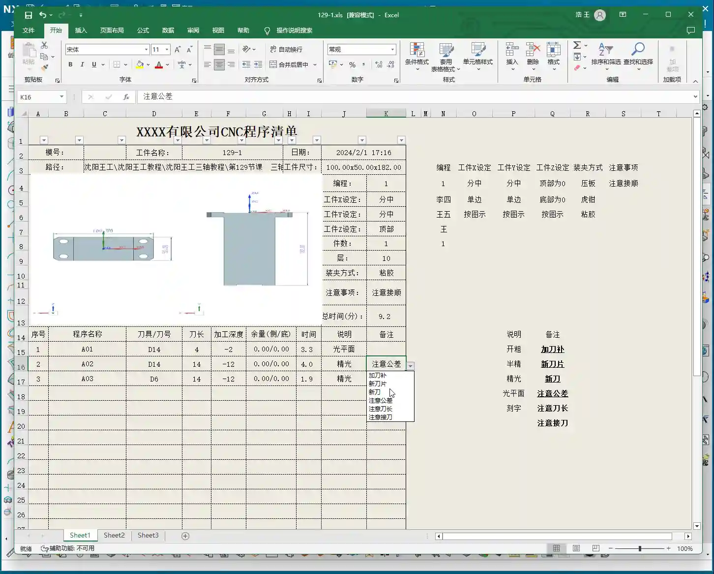
Description: Such as Remarks: This is a treasure trove! Here, you can jot down all sorts of ‘Pay attention to tolerance’, ‘Change to a new tool’, ‘Mind tool blending’, and so on. These are crucial reminders for the operator to ensure machining quality and efficiency. This section can also be customized in the template; add all your frequently used precautions.
Master Wang’s Wisdom: Practical Tricks for Operation Sheets
Just knowing how to generate an operation sheet isn’t enough; the key is knowing how to use it, how to make it ‘come alive’.
Division of Labor: Post-Processing vs. Operation Sheet: We choose ‘Output Operation Sheet Only’ because post-processing (G-code) requires separate review and verification, while the operation sheet serves as direct instructions for the operator. Keeping them separate clarifies responsibilities and improves efficiency.
The True Meaning of ‘Tool Length’: Remember, the tool length on the operation sheet refers to the fixturing. It’s better to clamp it a bit shorter for more stability than to risk clamping it too long.
Applying ‘Machining Depth’ Flexibly: Don’t mistake the ‘machining depth’ in each program segment as the final depth. It could be the single The Value of the ‘Remarks’ Section: This is where your experience truly shines! Here, you can jot down any ‘frequent air blasts’; if a feature has tight tolerances and requires ‘this tool needs to be replaced halfway through machining’. These are all critical for improving machining quality and reducing scrap.
Path Standardization: My habit of using a dedicated NC folder on the D: drive is all about Template Customization: This is also a big deal! Integrate your company’s commonly used information, standard operation sheet template. This will save a lot of effort every time you generate one and ensure the Master Wang’s Perspective: The ‘Siemens NX + SEO’ One-Two Punch for Industrial Product Promotion
Folks, don’t think I, Master Wang, only know how to write code and sharpen tools. In this day and age, even great products need a good shout-out. Our work on operation sheets isn’t just for production; it’s also excellent material for industrial product promotion.
See, all these detailed processes – Siemens NX modeling, 5-axis simultaneous programming, toolpath optimization, and then today’s topic, operation sheet creation – each step embodies our core technology. Share these practical experiences and technical details through articles, tutorials, and case studies on our official website, industry blogs, or even platforms like Zhihu and Bilibili, accompanied by high-definition Siemens NX screenshots and machining videos. The impact will be completely different!
For example, you could break down the Setup A machining process for a complex part, from modeling to the operation sheet, explaining it step-by-step. Tag it with ‘Siemens NX 5-Axis Programming’, ‘Complex Surface Milling’, ‘Titanium Alloy Machining Process’, ‘Precision Fixture Design’. When potential customers search for these technical solutions online, they’ll find us. Doesn’t that mean we’re directly showcasing our ‘content marketing’, combined with
Summary: Pitfall Avoidance Guide
Operation Sheet ≠ Post-Processed G-code: They have different functions and different purposes; do not confuse them.
Don’t Blindly Trust Times: The machining time on the operation sheet is for reference only; actual conditions may vary due to machine status, operator habits, and other factors.
Utilize the Remarks Section: Don’t underestimate the remarks! It’s the most direct and effective Template Standardization: Customize your operation sheet templates in advance. This will not only improve work efficiency but also ensure information accuracy and consistency, reducing human error.
👤 About the Author: The author is a veteran CNC machining professional with 15 years of industry experience, specializing in UG NX programming. This article is an original work representing personal practical insights.
⚠️ Copyright Notice: Unauthorized reproduction or distribution without prior communication is strictly prohibited.
Hello everyone, I’m Master Wang. Today, let’s talk about machining two-sided parts, a common “tough nut to crack” in the workshop. Textbooks cover a lot of theory, but when you get hands-on, especially with flipping and fixturing, that’s where the real expertise comes in. Today, I, Master Wang, will walk you through it step-by-step using this case study.
Workpiece Analysis and Process Strategy
Listen up: any time you get a new part, don’t rush into programming. First, you need to understand the part’s characteristics. Our part here is a typical two-sided machining component.
Part Overview and Dimension Assessment
First, let’s look at the dimensions: Length 460mm, Width 200mm, Height 115mm. It’s a sizable component, and the height, in particular, requires attention to stability during machining. As for material, typically, such parts initially use aluminum, where light cuts and fast feed rates are the basic principles. However, if you switch to stainless steel or titanium alloy, the machining parameters and tool selection will be entirely different.
Analyzing it, the front side mainly consists of flats and contoured surfaces, without any particularly tricky deep pockets. The edges have small chamfers, which is standard practice. The back side has similar structures but is machined after flipping the part. So, overall, it’s a “normal” part, but “normal” often means that meticulous detail work is required to demonstrate true skill.
Blank Setup and Datum Selection
For blank creation, we can allow for a bit of extra material, or create it directly to the nominal dimensions, depending on your shop’s specific practices. I usually put the blank on layer 100 and copy the part to layer 10, which keeps things clear and simplifies programming.
The key is the Work Coordinate System (WCS) setup. For the first side, we can choose to center on the face (workpiece geometric center) or directly reference off a fixture corner – either is fine. But be aware: once established, it cannot be changed arbitrarily, especially after flipping the part. When machining the second side after flipping, the datum point cannot remain in the same position. After flipping, I typically choose to reference the X-axis from the fixture’s locating corner and center the Y-axis on the front edge. This is because we are now clamping on the lower area that was machined in the first operation, so finding the datum requires flexibility, not rigid adherence to one method.
Two-Sided Machining Approach and Fixturing Considerations
The overall machining process: first machine the front side, completing the roughing and finishing of the upper areas. Then, flip the part, clamp onto the already machined front surface, and machine the back side. This really tests the fixture design and usage. The fixture must be stable, preventing the workpiece from shifting or deforming during machining, especially when the part is tall. The clamping force also needs careful consideration; too much can damage the part, while too little risks instability. These are all skills learned through experience; you need to observe, listen, and feel the machine’s feedback.
Tool Selection and Roughing Practice
Choosing the right tool is half the battle. Don’t just think the most expensive is the best; the right tool for the job is king, and you also need to consider tool life and machining efficiency.
Roughing Tool Determination
For this part, we previously used a Ø32 R3 bull nose end mill for machining aluminum, and we’ll use it again. A bull nose end mill offers high roughing efficiency, good chip evacuation, and the corner radius reduces tip wear, making it a versatile tool. In Siemens NX, we’ll select the Cavity Mill operation, which is straightforward and efficient.
Stock allowance: Initially, leave around 1mm, providing ample space for subsequent finishing passes.
Cut pattern: Follow Part, for a smoother toolpath.
Blank Layer and Toolpath Control
Layer management is very important in Siemens NX programming. Keep the blank on a separate layer for easy selection during programming. For roughing, pay attention to this detail: since there are small chamfers around the edges, we can extend the Depth of Cut (DOC) a bit further down, for example, machining to a depth of 68mm. This roughly removes material in the chamfered areas too, reducing the burden on finishing. Don’t underestimate these few millimeters; they effectively prevent the tool from experiencing sudden heavy loads during finishing, which can affect surface quality or even cause tool chipping.
When programming, pay special attention to optimizing “air cuts”. Properly adjusting Siemens NX’s “Minimum Engage” and “Non-Cutting Moves” settings can save significant machining time. Regularly review the IPW (In-Process Workpiece) simulation; although it doesn’t fully represent reality, it can at least help you identify potential issues.
Roughing Techniques for Chamfer Treatment
For small bevels or chamfers around the part, simply allow the bull nose end mill to cut a bit deeper during roughing to remove most of the material. This is a simple and efficient method. Don’t expect one tool to do everything; detailed finishing still relies on specialized tools. Roughing is primarily for quickly removing the bulk of the material, reducing the load for subsequent finishing operations.
Finishing Strategy and Detail Optimization
After roughing comes finishing. This stage determines the final accuracy and surface finish of the part, so it cannot be taken lightly.
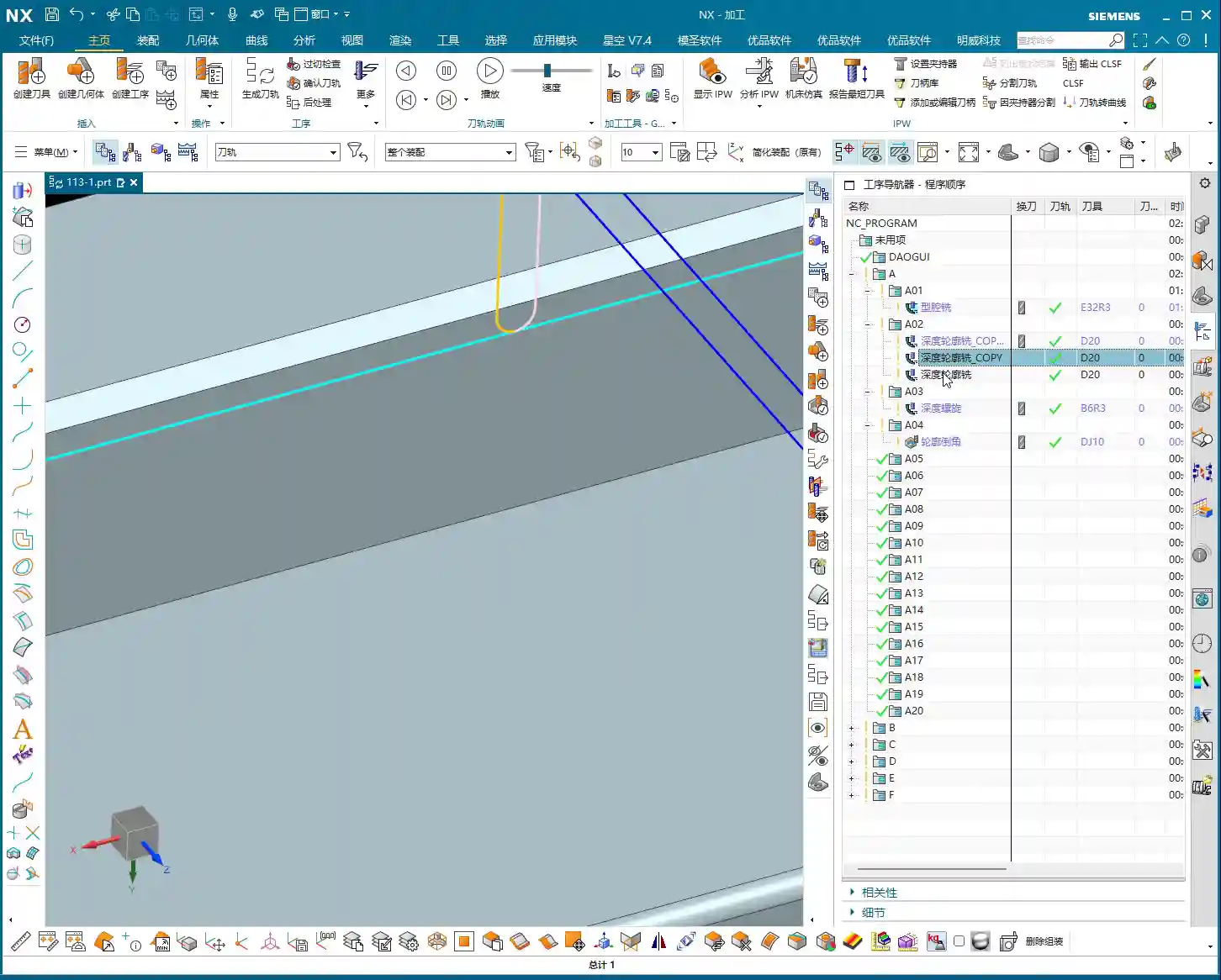
Side Wall Finishing
For side wall finishing, we’ll use a Ø20 flat end mill. This tool size is appropriate, and its rigidity is sufficient to produce a beautiful finish on the side walls. In Siemens NX, you can choose Contour Profile or Curve Mill to accomplish this. Don’t forget to select both the side walls and the bottom surface to ensure toolpath coverage.
Cutting Parameters:
Depth of Cut (DOC): Full-depth cut is preferred to minimize tool retractions. If tool rigidity or machine power is insufficient, you can use multiple layers.
Stepover: Adjust according to the required surface roughness, typically maintained at 5%-10% of the tool diameter, or even less.
Stock allowance: Set to 0 for a direct finish cut.
In actual operations, we sometimes encounter situations where the tool cannot reach certain areas, or a single tool cannot cover the entire surface. For example, as mentioned, a 25mm distance might be unreachable with a 20mm tool. In such cases, you must flexibly adjust the cutting range or switch to a smaller diameter tool; do not try to force it.
Bottom Surface Finishing
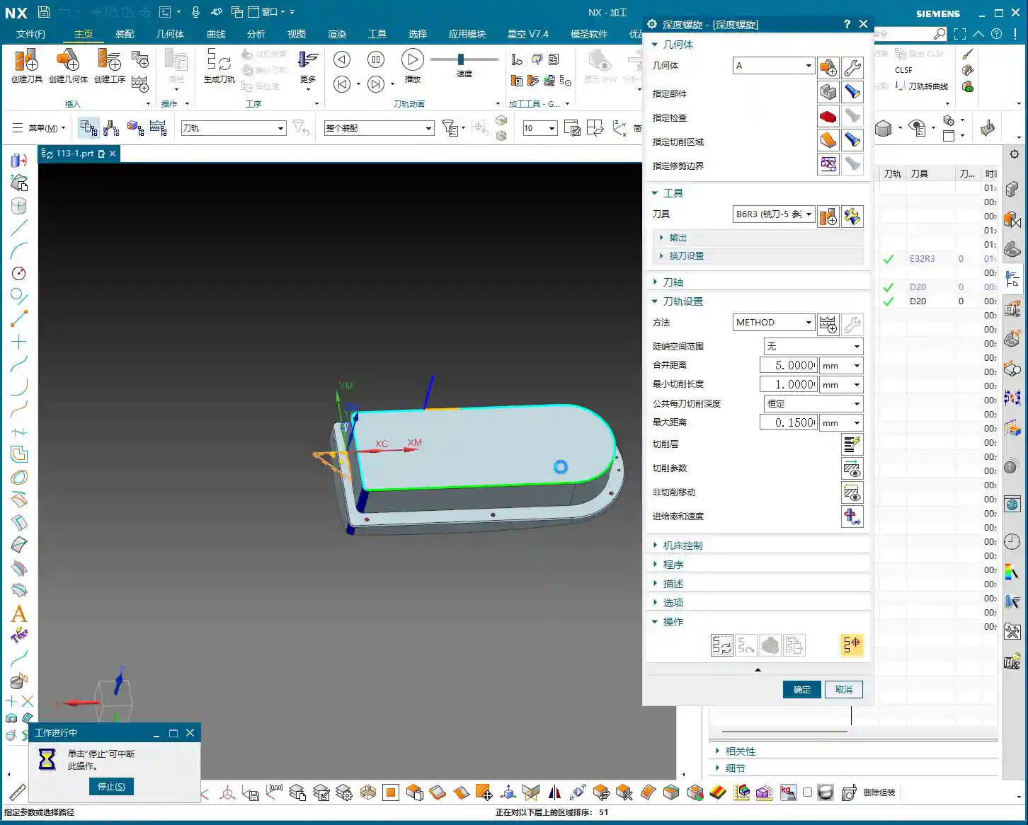
For finishing bottom surfaces, a ball nose end mill usually gives the best results, especially for contoured surfaces. Here, we’ll use a Ø5 ball nose end mill for Contour Milling. The advantages of a ball nose end mill are smooth cutting and the ability to produce excellent surface finish, although its efficiency on flat surfaces is relatively lower.
Siemens NX Operation:
Select Fixed Axis Surface Contour or Area Mill.
Tool selection: Ø5 ball nose end mill.
Cutting parameters: Similarly, set the stepover according to the precision and surface finish requirements.
The finishing sequence, whether to finish side walls first then bottom surfaces, or vice versa, is flexible. The key is to choose the approach that better protects already machined surfaces, reduces secondary damage, and ensures smooth chip evacuation.
Small Hole and Chamfer Finishing
Small holes and chamfers on the part are detail work. For an 11mm small corner, a Ø20 tool can be used for the finish cut; for an 8mm corner, a Ø12 or Ø16 tool can be used for Corner Cleanup. For even smaller chamfered areas, a Ø4 or Ø6 ball nose end mill is suitable for cleanup. Smaller tools have lower rigidity, so cutting parameters must be conservative; feed rate and spindle speed must be properly matched to prevent tool chipping or chatter marks.
Siemens NX Programming Tips:
Use Corner Cleanup or Point Milling operations.
Pay attention to lead-in and lead-out paths to avoid collisions or scratches in corners.
Summary: Pitfall Avoidance Guide
I, Master Wang, have been at this for many years, and I’ve stepped into my share of pitfalls and learned a lot. Here are a few key takeaways for you, skills that you won’t find in textbooks:
Clamping and Deformation: The biggest problems in two-sided machining often arise here. An unstable workpiece or excessive clamping force leading to deformation is a cardinal sin. Especially for tall parts, always use a stable fixture to ensure rigidity. After flipping, already machined surfaces can be quite thin, so use soft jaws or pads to distribute clamping force and prevent crushing or deformation.
Coordinate System Accuracy: The accuracy of the WCS after flipping is critical. The X and Y zero points must be precisely located, and the Z-axis Tool Offsetting must be meticulous. If conditions allow, use an edge finder or CMM (Coordinate Measuring Machine) to ensure that the flip-over error is within tolerance. Don’t rely solely on visual inspection; it’s not precise enough!
Stock Allowance Control: Roughing stock allowance should be sufficient, but not excessive. Too much increases the burden on finishing; too little can lead to undercutting after roughing. Finishing stock allowance is generally distributed evenly, which stabilizes the tool’s cutting load and improves surface quality.
Tool Life and Cost: Don’t try to save a few bucks by using dull or unsuitable tools. Tool life and machining efficiency are a balancing act. For aluminum, coated tools are good, High-Speed Steel (HSS) can also work, but cutting parameters must be adapted. For titanium alloys and nickel-based superalloys, carbide tools are a must, and they should have custom-optimized geometries.
Machining Sequence Optimization: Rough first, then finish; large features first, then small; flats first, then contoured surfaces; internal features first, then external profiles. These are fundamental principles. Also, consider chip evacuation direction; don’t let chips accumulate in the machining area, as this affects tool life and surface quality.
Preventing Overcutting and Undercutting: Especially in areas like Corner Cleanup and chamfers. Siemens NX’s simulation is just a reference; during actual cutting, observe the spark color and listen to the tool sound. If the sparks are too bright or the sound is sharp, it indicates too aggressive a Depth of Cut (DOC); adjust parameters immediately.
Machine Accuracy Compensation: Even the best machines have errors. For high-precision requirements in the ±0.005mm range, in addition to proper initial process planning, post-machining machine compensation might be needed. This requires deep knowledge of the machine itself to determine whether the error is mechanical or due to thermal deformation, and then apply targeted compensation. This is a veteran machinist’s core expertise, not something everyone can master.
Chip Evacuation and Cooling: Don’t underestimate chip evacuation and coolant. If chips are not removed promptly, they can be re-cut, wearing down the tool and scratching the workpiece surface. Coolant selection must be appropriate, and flow rate and pressure must be sufficient to maintain the cutting zone temperature within a reasonable range.
Alright, brothers, that’s all for today. Theoretical knowledge is important, but practical experience is even more valuable. Get hands-on, think critically, and observe closely to truly become a skilled machinist!
👤 About the Author: The author is a veteran CNC machining professional with 15 years of industry experience, specializing in UG NX programming. This article is an original work representing personal practical insights.
⚠️ Copyright Notice: Unauthorized reproduction or distribution without prior communication is strictly prohibited.