📝 Key Takeaways:
Siemens NX (UG) Operation Sheet for Setup A: Practical Deep Dive
…
[VIDEO_HERE]
Overview: The Importance and Core Function of the Operation Sheet
Listen up, folks! In mechanical machining, no matter how perfectly you program toolpaths in Siemens NX, if you can’t clearly convey that information to the shop floor operators, it’s all for nothing. The operation sheet, simply put, is the ‘interpreter’ and ‘guidebook’ connecting us programmers with the machine operators. It absolutely must clearly detail how to fixture the part, which face is up, what areas to machine in each step, what tools to use, and what precautions to take. Today, we’re going to start with the most fundamental and critical Setup A operation sheet, and I’ll walk you through how to generate it, and more importantly, how to interpret and effectively utilize it!
Siemens NX (UG) Operation Sheet Generation: Practical Steps
Step One: Select Programs for Output and Initial Verification
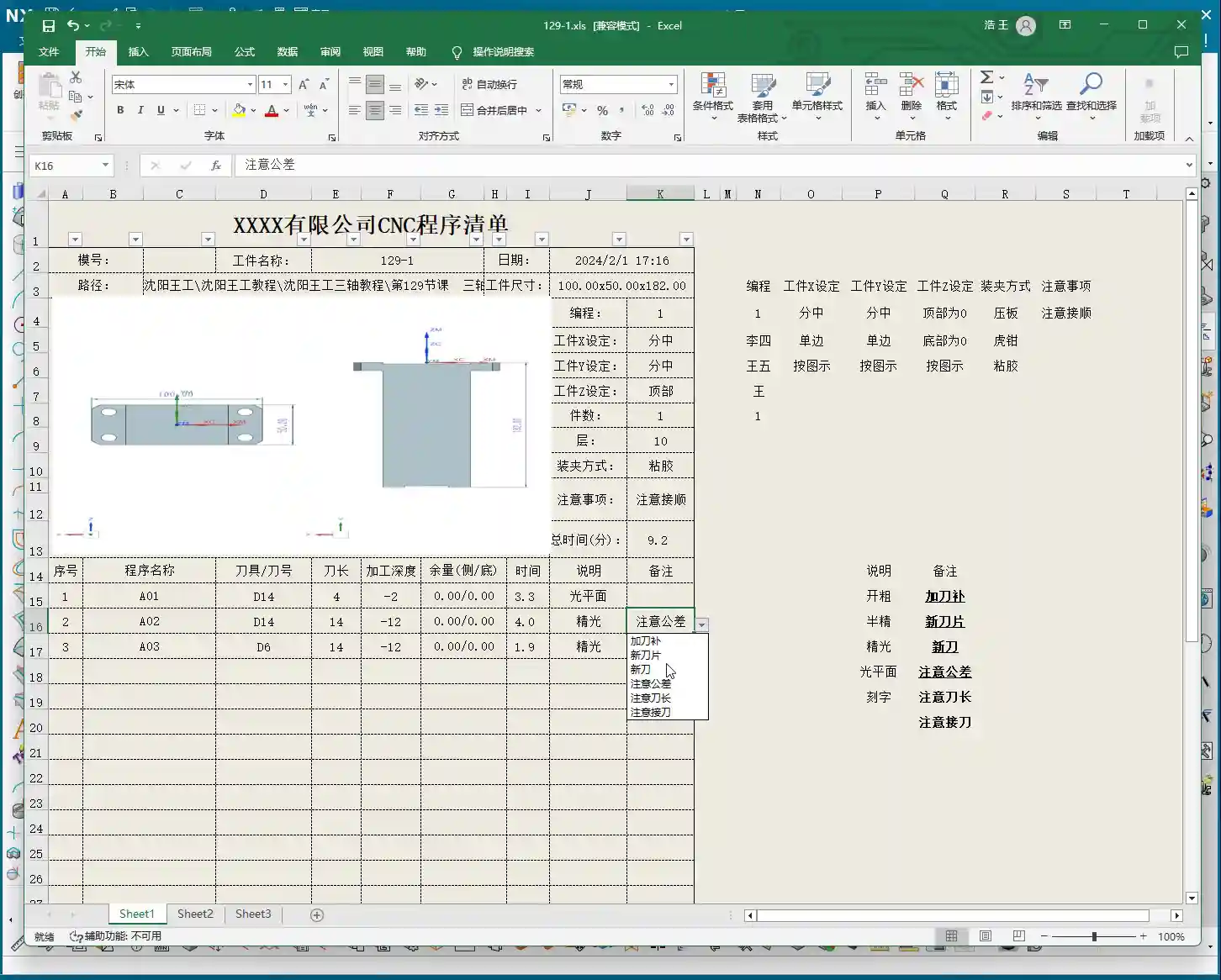
In Siemens NX, first, select all the toolpath programs you want to output an operation sheet for (e.g., A01, A02, A03 for Setup A). Once selected, here’s a good habit: always simulate the toolpaths first to ensure there are no issues and that the fixturing is appropriate.
For a part like this one, Setup A involves machining a single face. So, when clamping, you need to secure the part in a vise, exposing the face to be machined. Simulating it gives you a clear understanding. It also provides the operator with a visual machining preview, building confidence and reducing the chance of errors.
Step Two: Select the ‘Generic Operation Sheet’ Function
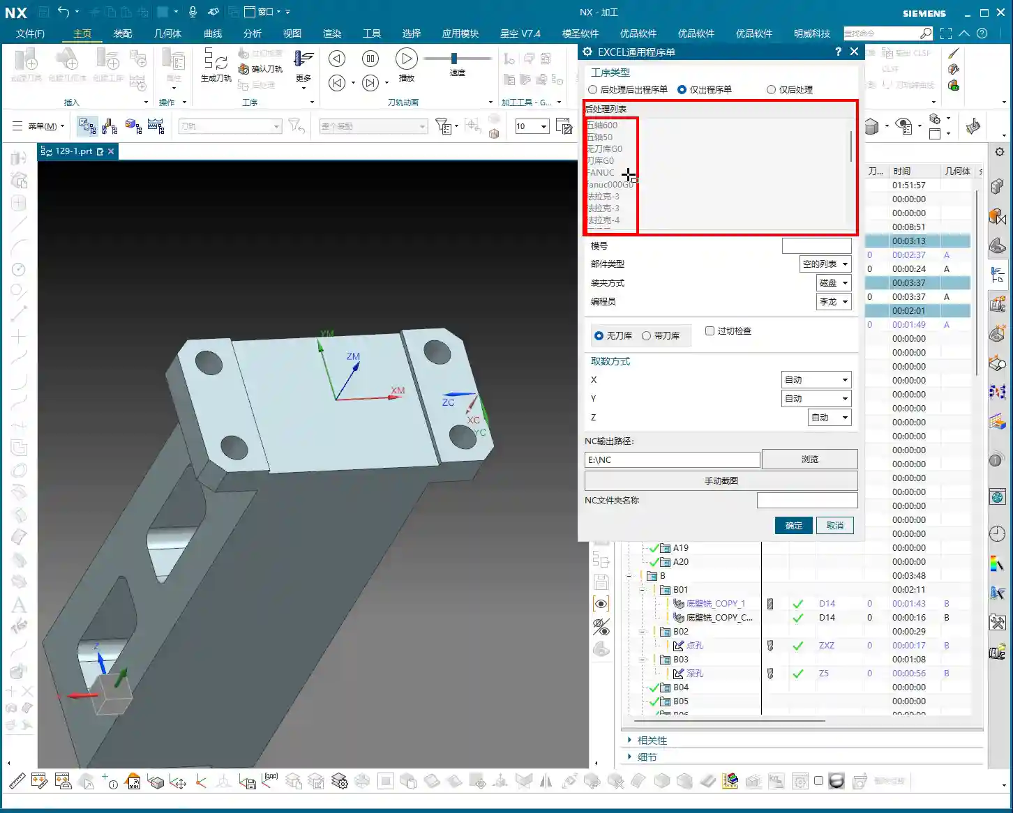
Toolpaths are good, programs are selected. Next, it’s time for the crucial step of outputting the operation sheet. In the Siemens NX menu, find the ‘Generic Operation Sheet’ option. For us, this is usually achieved through the ‘Starry Sky’ plugin. Just click it.

Step Three: Understand Output Options and Path Settings
Once open, you’ll see several output types:
- ‘Post-Process and Output Operation Sheet’: This means outputting both the G-code (post-processed file) and the operation sheet simultaneously.
- ‘Output Operation Sheet Only’: This outputs only the operation sheet; we can handle the G-code separately later.
- ‘Output Post-Process Only’: This outputs only the G-code.
Since we’re focusing on operation sheets today, select ‘Output Operation Sheet Only’. When you do, you’ll notice the ‘Post-Process List’ section is empty. That’s perfectly normal, just ignore it. As for the ‘Tables’ and other options below, those are more detailed settings we’ll cover later; you can safely disregard them for now.
Regarding the output path, many people just stick with the default. But listen up, I, Master Wang, have a personal habit: I typically create a dedicated ‘NC’ folder on my D: drive or another non-system drive, and I put all post-processed files and operation sheets in there. This makes management easier, finding files quicker, and prevents clutter. You might want to adopt this practice.
Step Four: Confirm and Generate the Operation Sheet
Once all previous settings are configured, just click ‘OK’. No need to mess with any other parameters; the operation sheet will be automatically generated and saved to your specified path.
In-Depth Interpretation of Key Information in the Setup A Operation Sheet

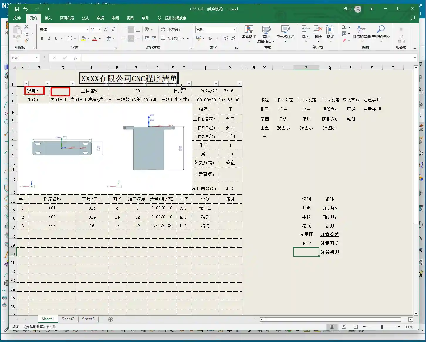
Part Basic Information and Datum Reference
- Dimensions: The operation sheet will clearly specify the part’s length, width, and height. For example, our part here is 100mm long, 50mm wide, and 182mm high. These are the final finish cut dimensions, so the operator knows the part’s size at a glance.
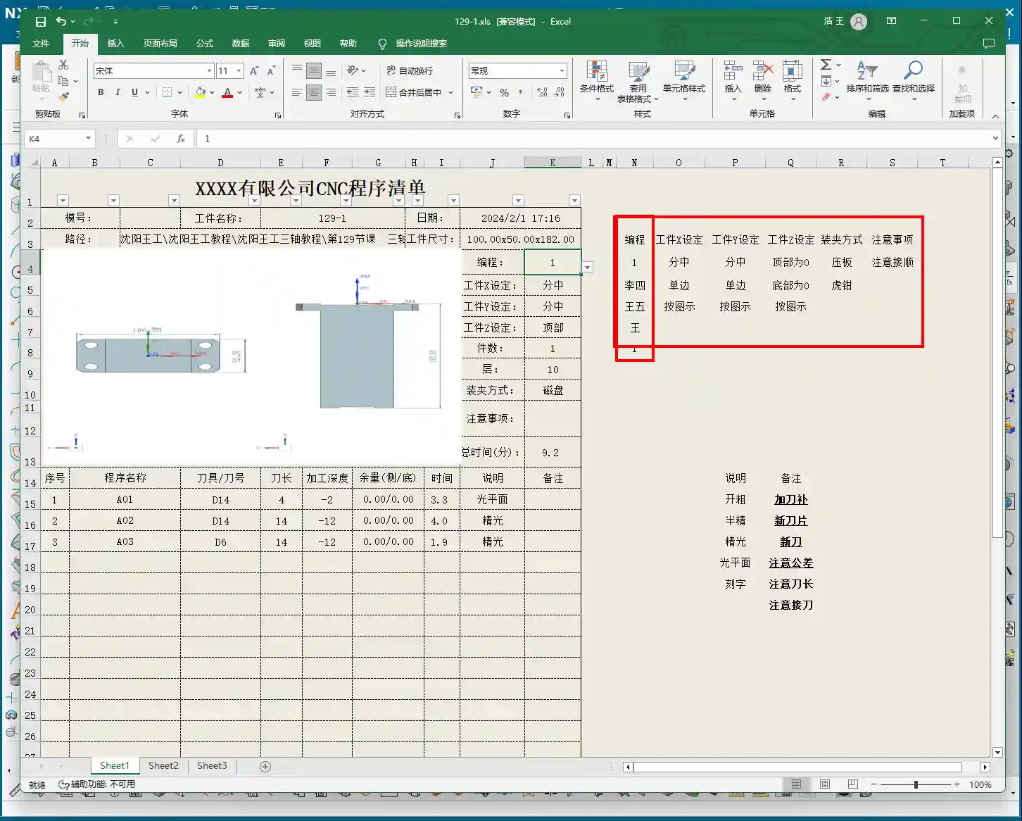
- Locating Datum: This is critically important! The operation sheet will clearly state the tool offsetting method. For example, here it’s ‘Center X & Y, Top Face Zero’. This tells the operator exactly where the tool offsetting origin is for the X, Y, and Z axes – absolutely no room for error.
- Views: The automatically generated XY and XZ views from Siemens NX provide a clear visual of the part’s machining faces and tool offsetting points. When operators see these diagrams, they’ll have a crystal-clear understanding of the features to be machined and the datum locations. Don’t just rely on software simulations; look for the cutting sparks! Drawings are merely aids; the shop floor is where reality happens.
Company and Workpiece Information
- Mold/Job Number: This section can be filled according to your company’s specific requirements. If you want it to display the company name or a particular mold number, you can preset it in the operation sheet template. How do you modify the template? I’ve covered that in detail in my previous video tutorials; go check them out yourself – it’s fundamental!
- Workpiece Name: For example, Programmer and Date
- Prepared By: Here, I’ve put ‘Wang’. You can enter your own name or employee ID. This is also something you modify in the template; set it once, and it will auto-populate thereafter.
- Date: The specific date and time the operation sheet was generated, such as


Leave a Reply