Tag: Mold Machining

  • Mold Part Siemens NX Programming Practical Guide: Master Wang Details Toolpath Segmentation for Enha

    📝 Key Takeaways: ** Master Wang details practical Siemens NX programming for mold parts. From roughing to finishing, he elaborates on tool selection, stepover and depth of cut, allowance control, and toolpath segmentation strategies. Emphasis is placed on optimization techniques for “Contour Milling” on sloped surfaces and “Z-Level Milling” for side walls, along with how to resolve issues like unnecessary tool lifts and missed cuts by adjusting parameters. Practical application is key, and these pitfall avoidance tips will help you boost efficiency and precision. **

    Overall Machining Strategy and Tool Selection

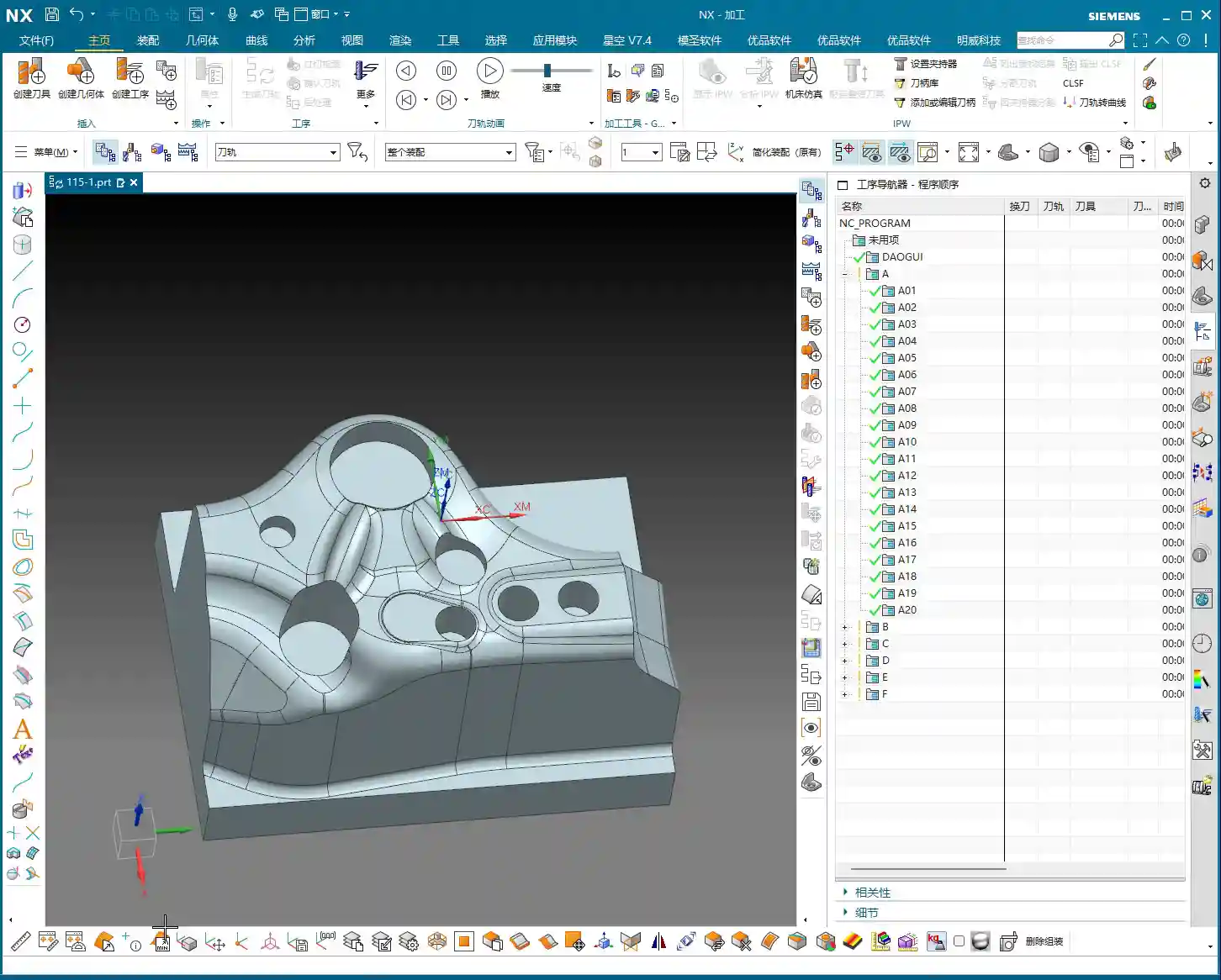
    Process Sequence: Roughing First, Then Finishing, Step-by-Step

    Listen up, lads. In mold making, process is everything. Once this area is done, the next step is roughing with an R2 ball end mill to quickly remove the excess material. After that, make sure the part surface is finished smooth, and finally, meticulously clean up the side walls. Don’t mess up the sequence; if you do, it’s rework, and that’s not a joke – that’s money!

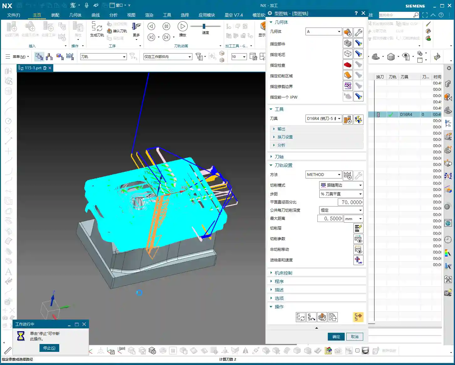
    Tool Selection for Mold Surface Finishing

    Once roughing is done, for surface finishing, you must use a ball end mill. As I said earlier, a small R2 ball end mill, or larger ones like R4, R6, are all acceptable, depending on the workpiece size and your desired machining allowance. For mold parts like this, we typically use a 16R4 ball end mill. Its stepover is 0.2mm, and depth of cut is 5mm. These parameters depend on your tool rigidity, material hardness, and machine tool stiffness. Don’t blindly copy them; too small, and efficiency drops; too large, and you risk chipping the tool. Especially with depth of cut – if you take too aggressive a cut, the tool is finished. And don’t ever use a flat end mill to finish curved surfaces; that’s just foolishness!

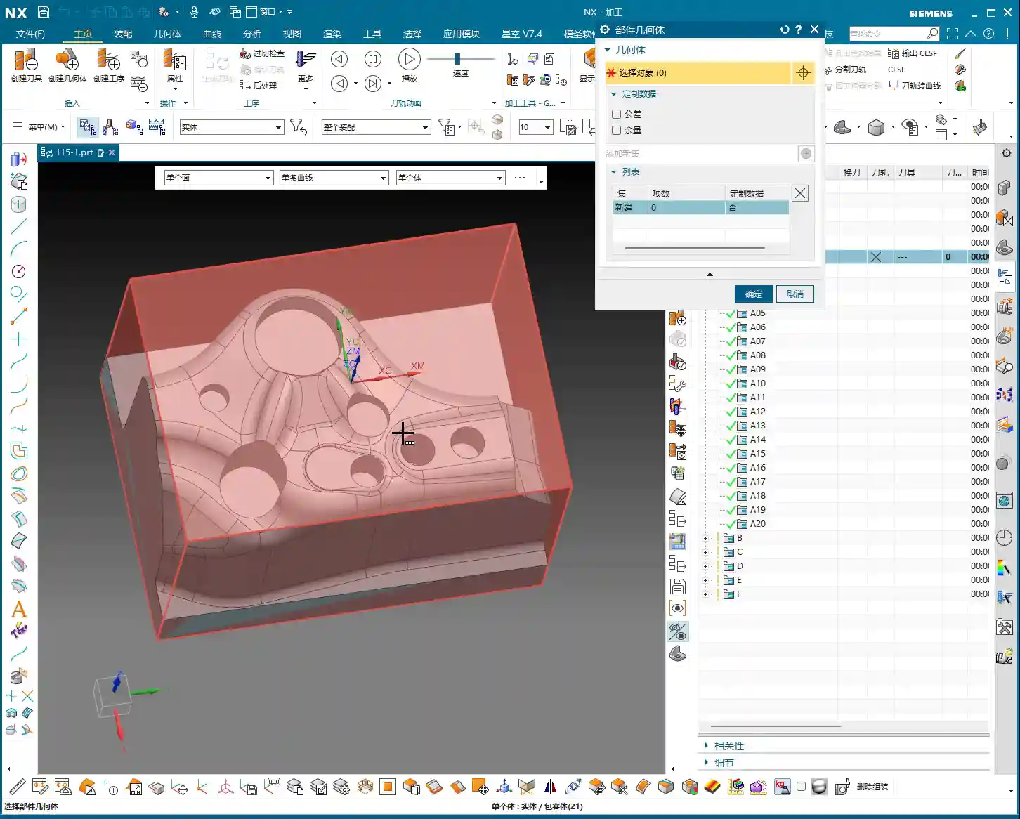
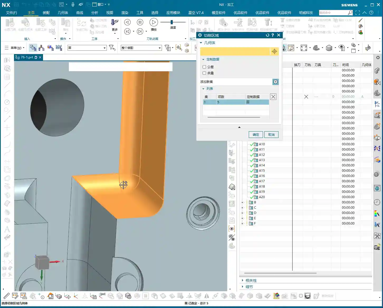
    Precise Definition of Stock and Machining Area

    Selecting the stock and machining faces is fundamental, but also where mistakes are most often made. Miss a selection, and it won’t be machined; over-select, and you’ll cut what shouldn’t be cut, and then it’s too late to cry. Choosing the correct stock is crucial, otherwise, the software calculates endlessly, and in actual machining, you’ll either have tool crashes or air cuts, wasting time, effort, and material. Especially for parts with root areas, if roughing has already cleared most of it, you can wait to address it when finishing the side walls, avoiding redundant machining. Here, we’ve decided to only clear the top, leaving the bottom untouched. Use the ‘Boundary Intersection’ function to lock down the toolpath boundary precisely, with the final pass stopping exactly at the specified point. This method ensures high machining efficiency without interfering with other areas.

    Detailed Toolpath Strategies for Critical Areas

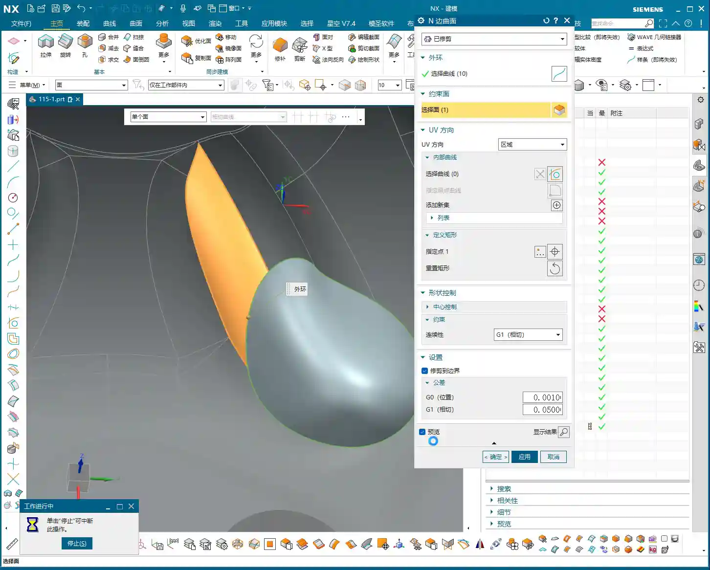
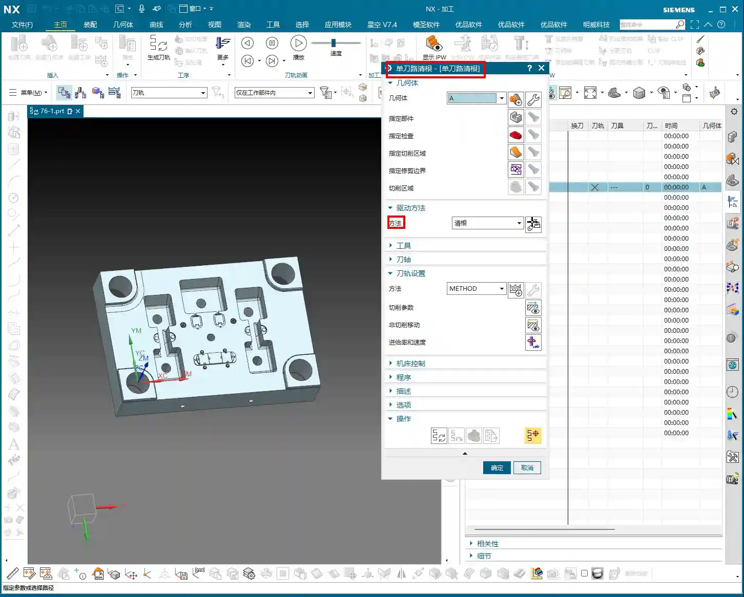
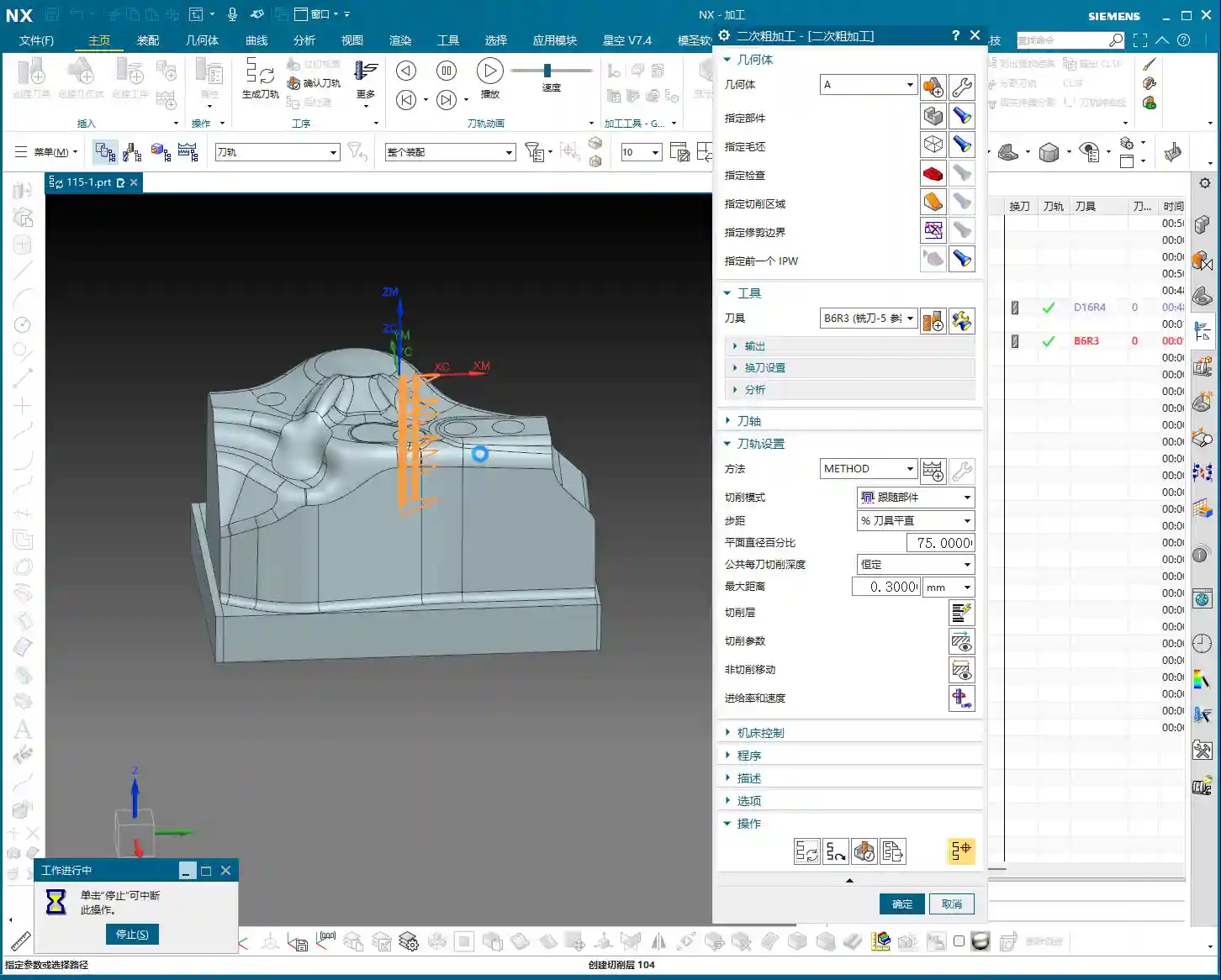
    Toolpath Optimization for Sloped Areas using “Contour Milling”

    When encountering areas with significant slopes, the most effective toolpath in Siemens NX is ‘Contour Milling’. It follows the surface, producing an exceptionally good surface finish. However, be wary of unnecessary tool lifts/retracts! During toolpath simulation, if you see the tool frequently lifting and re-engaging, there’s definitely an issue. Excessive tool lifts not only reduce efficiency but also tend to leave marks at the entry and exit points. If you spot unnecessary tool lifts, check your toolpath parameters, such as lead-in/lead-out methods and angle settings. Here, I adjusted the lead-in/lead-out angle to 45 degrees, and the tool lifts disappeared immediately. These little tricks aren’t found in textbooks; they’re accumulated through experience.

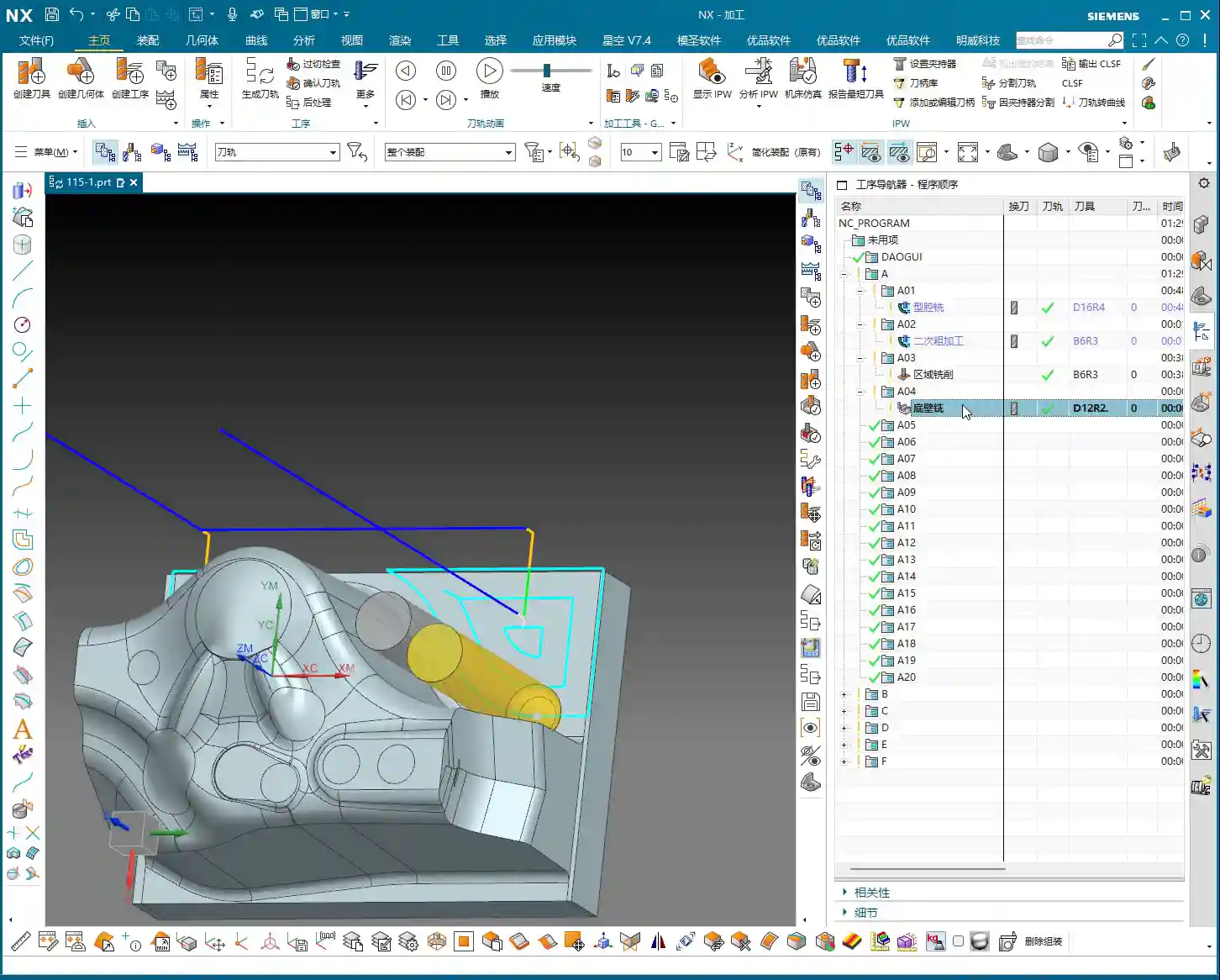
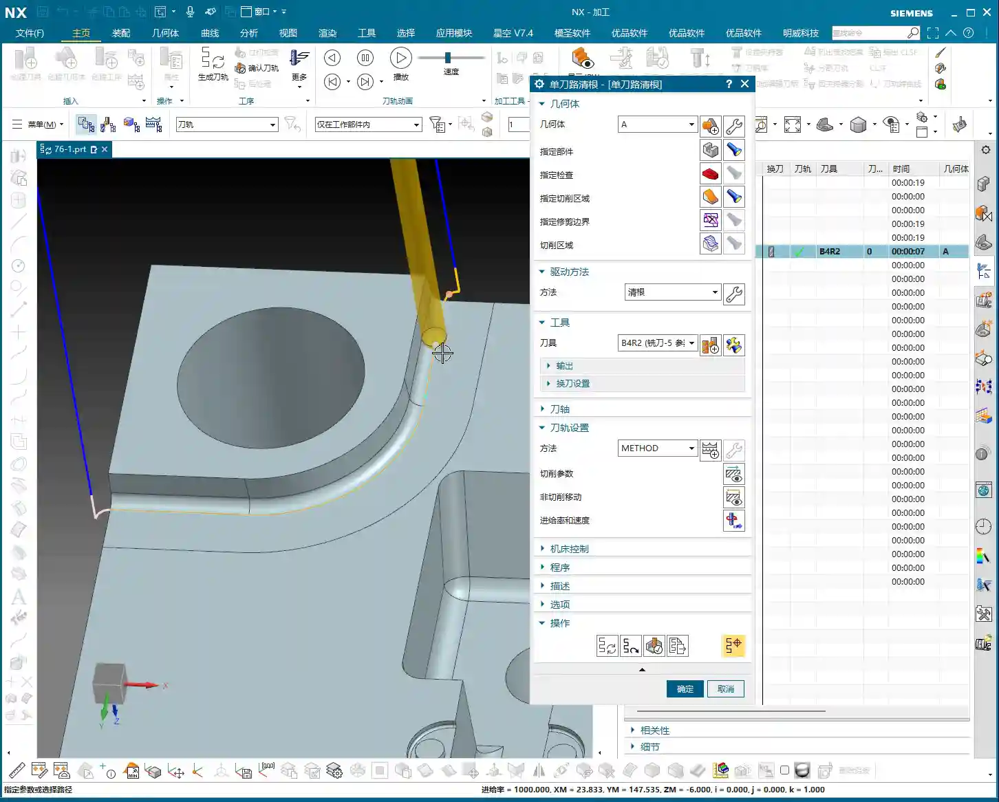
    Step-by-Step Finishing of Side Walls and Bottom Surfaces

    For finishing side walls and bottom surfaces, I typically start by using a flat end mill or a radius end mill to finish the bottom surface clean, setting the machining allowance directly to zero. Then, I switch to a 12R2 tool and use either ‘Z-Level Milling’ or ‘Follow Periphery’ methods to perform a finishing pass on the side walls. For side walls, you can leave a small allowance, for instance, 0.5mm, which facilitates subsequent final polishing or fine finishing. The machining direction is from top to bottom; this is climb milling, which provides good chip evacuation and a high surface finish. For complex geometries, I often use ‘Mixed Milling’ to achieve smoother toolpaths, reduce unnecessary tool lifts, and enhance surface quality.

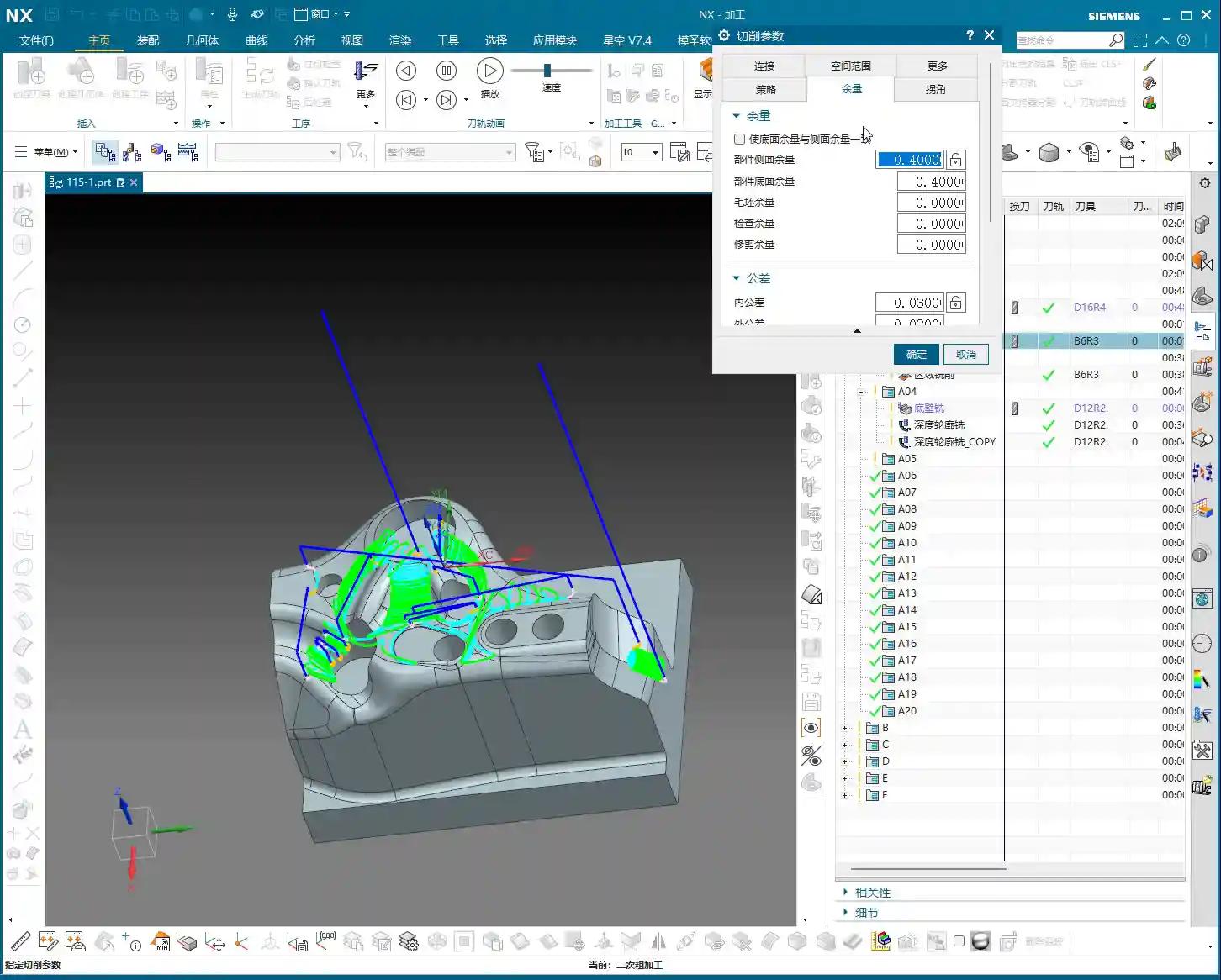
    Machining Allowance Control and Feed Rate Adjustment

    Machining allowance is a profound topic. Leaving 0.5mm on side walls and zero on bottom surfaces balances both accuracy and efficiency. But look at the allowance after roughing: 0.35mm – that’s a bit too much! Next time you rough, you can reduce it to around 0.2mm, or even smaller, depending on the material and tool. Leaving too much allowance means the finishing pass has to take more cuts, wasting time and tool life. Also, regarding feed rate (cutting speed), setting it to 400 in Siemens NX is already the maximum; don’t push it higher. The machine has its limits; exceeding them will either cause an error or lead to excessive machine chatter, affecting machining quality. Remember, stability is paramount!

    Siemens NX Operation Tips and Efficiency Improvement

    Parameter Adjustments to Avoid Unnecessary Tool Lifts

    I’ve emphasized this many times: unnecessary tool lifts are a major machining taboo. Every time the tool lifts and re-engages, it not only wastes time but can also leave subtle tool marks on the workpiece surface, affecting the surface finish. Besides adjusting the lead-in/lead-out angle, you can also try adjusting parameters like connection methods and retract height. The goal is singular: to make the toolpath as smooth as possible and minimize unnecessary tool lifts. For example, by adjusting the angle to 45 degrees here, the issue of unnecessary tool lifts was resolved instantly.

    Precise Control of Toolpath Boundaries and Depth

    If the toolpath finishes and you find the machining is incomplete, don’t rush to blame the software. First, check your cutting levels depth and toolpath extension amount. For example, if it wasn’t machining to the bottom here, I directly added 2.2mm downwards in the cutting levels, and the problem was solved. This is the kind of detailed work required to control accuracy to the ±0.005mm level. As for the hole features, those are fundamental basics; program them yourself using hole milling. I won’t demonstrate it here; it’s too elementary. Of course, some auxiliary features that don’t affect the current toolpath can be deselected to reduce calculation time.

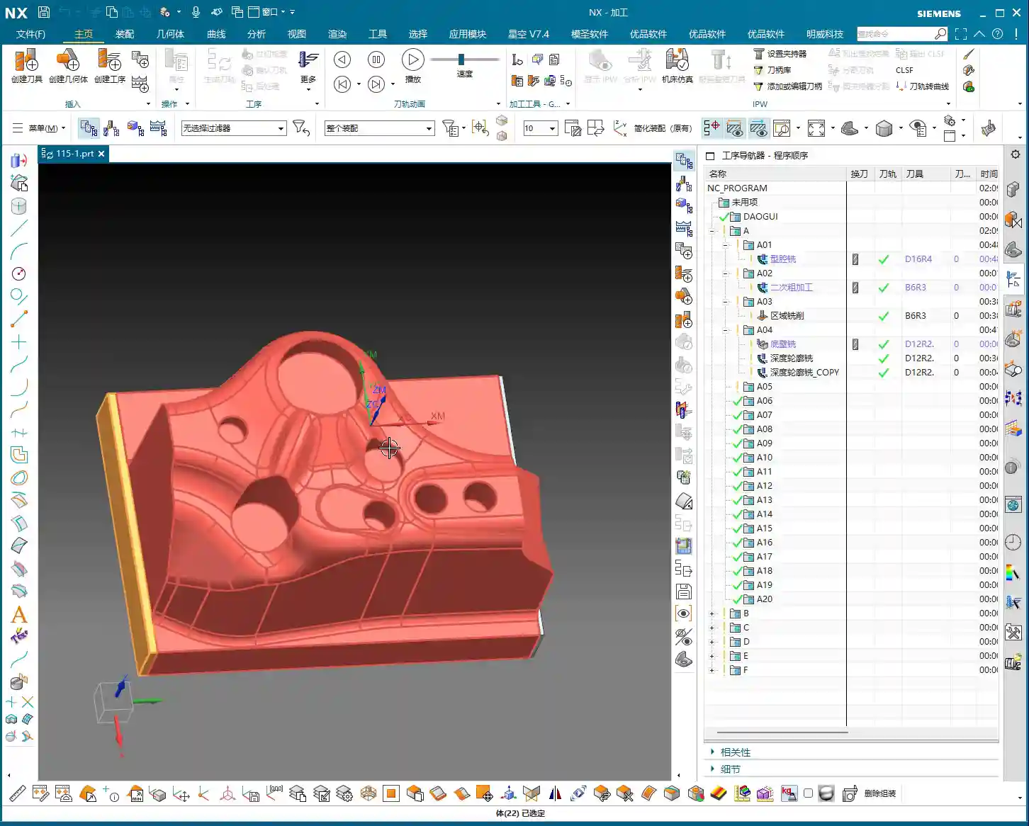
    Toolpath Simulation and Verification

    Toolpath simulation is your last line of defense before going to the machine! Every time you finish programming, regardless of the complexity, diligently simulate it. Especially for roughing toolpaths, focus on checking for any missed cuts, gouges (overcuts), or tool collision risks. During simulation, you can speed it up appropriately to get a general overview. As for those auxiliary bodies, once machining is complete, hide them from view to avoid clutter and prevent thinking some strange extra parts have appeared on the component.

    Summary: Pitfall Avoidance Guide

    Alright, we’ve covered a lot of practical knowledge today. Finally, let me summarize a few pitfall avoidance tips for you, all derived from my 15 years of hands-on experience:

    1. Strictly follow the machining sequence: Rough first, then finish, step by step. Don’t rush for quick results.
    2. Tool selection demands attention: For mold surface finishing, the ball end mill is your primary tool. Proper parameter settings will yield twice the results with half the effort.
    3. Machining allowance is a science: Don’t leave too much roughing allowance (0.35mm is already excessive). For finishing, zero out the allowance where appropriate, and leave it precisely where needed.
    4. Eliminate unnecessary tool lifts to boost efficiency: Continuously inspect toolpaths, adjust lead-in/lead-out strategies and angles (e.g., 45 degrees) to avoid unnecessary tool lifts.
    5. Simulation and verification are paramount: Before every machine run, diligently simulate the toolpath and check for all potential errors.
    6. Be bold yet meticulous with parameter adjustments: For instance, if machining is incomplete, confidently adjust cutting levels or extension amounts (e.g., add 2.2mm downwards), but calculate precisely; don’t guess.
    7. Keep material properties in mind: Cutting parameters vary significantly for different materials, from common aluminum to titanium alloys and high-temperature nickel-based superalloys – always be aware.
    8. Fixturing solutions are fundamental to machining: Even the best toolpath is useless if the workpiece isn’t securely fixtured.
    9. Master the grinding of custom tools: Sometimes standard tools won’t cut it; being able to grind your own suitable tool is true skill.

    These are the tools of your trade for the future. Study them carefully, don’t just listen with your ears – think with your mind, and practice with your hands!

    👤 About the Author:
    The author is a veteran CNC machining professional with 15 years of industry experience, specializing in UG NX programming. This article is an original work representing personal practical insights.

    ⚠️ Copyright Notice: Unauthorized reproduction or distribution without prior communication is strictly prohibited.

  • High-Efficiency Roughing of Mold Components: Master Wang’s Guide to Avoiding Pitfalls and Optimizing

    📝 Key Takeaways:

    Roughing Practicalities for Mold Components

    Hello everyone, I’m Master Wang. Today, let’s talk about programming the roughing operation f…

    [VIDEO_HERE]

    Hello everyone, I’m Master Wang. Today, let’s talk about programming the roughing operation for this mold component. Don’t let its small size fool you; there are many intricacies involved, and a slight oversight can lead to significant problems. Listen up.

    Part Analysis and Stock Definition

    In-depth Analysis of Part Features

    When you get a new part, the first thing you need to do is examine it thoroughly. Don’t rush straight into it; that’s what novices do.

    • This small mold component, while not large overall, is complex despite its size.
    • Looking at it, there are some holes. During roughing, we can initially ignore them, or even patch them up directly to reduce air cuts.
    • The most critical features are these fillets (R-radii). After careful analysis, most of them are R4. This value is the decisive factor for selecting our roughing tool.
    • There are also some sloping surfaces and undercut features. These are prime areas for issues. Don’t just rely on pretty toolpath simulations in Siemens NX; the sparks from actual machine cutting are the only true test! If these areas aren’t handled correctly, it can lead to over-machining or undercuts at best, or tool crashes and scrap at worst.
    • Some very minor tool marks or small undercuts, if they don’t significantly affect final accuracy and can be covered by subsequent finishing passes, can be temporarily ignored during roughing. But always keep them in mind.

    Scientific Stock Definition

    Stock definition is the starting point for machining, and it cannot be overlooked.

    • The Coordinate System must be clearly defined. This is the datum for all machining programs. If it’s off, everything that follows will be incorrect.
    • The stock dimensions should be slightly larger than our part. Especially in the Z-axis direction, I usually leave an extra 1-2 mm (approx. 0.04-0.08 inch) of material. Why? For easier clamping and to provide some leeway for subsequent machining—safety first!
    • When setting up the stock, create it directly using Siemens NX’s geometry or automatic blank functions, ensuring it covers the entire machining area.

    Roughing Tool Selection and Machining Strategy

    Matching Fillet Radii with Roughing Tools

    Tool selection is an art, not a guess; it requires a basis.

    • Since the smallest fillet radius on our part is R4, the radius of the roughing bull nose end mill must be smaller than R4. This ensures a suitable amount of material is left in the corners for subsequent semi-finishing and finishing passes.
    • I recommend choosing a 16mm (approx. 0.63 inch) diameter bull nose end mill with a 2mm (approx. 0.08 inch) corner radius (i.e., 16R2). This tool offers sufficient strength and rigidity for efficient material removal (high Depth of Cut), while also managing the R4 fillets for proper Corner Cleanup, leaving enough space for subsequent tools.
    • Remember: Roughing is about quickly removing the bulk of the material, not about achieving surface finish. Efficiency is paramount, but tool life and subsequent operations must also be considered.

    Toolpath Optimization and Pitfall Avoidance for Curved Surfaces

    This part features some sloping surfaces or slightly outward-curving undercut areas. These are roughing traps!

    • If you use a standard roughing toolpath directly, the tool is highly likely to overcut downwards on the sloped surface. This is a major machining taboo! At best, it affects accuracy; at worst, it causes a tool crash in an unintended area, leading to significant losses.
    • In Siemens NX, we can cleverly handle this using the “Thicken” or “Replace Face” functions.

      • For problematic sloping surfaces, I can selectively “Thicken” them slightly, for example, by extruding 2 mm (approx. 0.08 inch). This way, the roughing toolpath calculation will perceive this face as extended outwards, thus preventing the tool from overcutting downwards.
      • Alternatively, and more directly, “Replace” the original sloped face with a planar surface. However, ensure the replacement plane effectively guides the tool and doesn’t introduce new interferences after replacement.
      • The key is to ensure the tool only mills to the specified Depth of Cut during roughing, or “avoids” areas prone to issues, thereby reducing unnecessary risks.

    • Don’t just rely on software simulations and assume the toolpaths are smooth; that’s only an ideal state. During actual machining, always pay attention to the cutting sparks, sound, and even machine vibrations—these are all real-time feedback.

    Hole Treatment and Toolpath Generation

    If the holes on the part are too small for the roughing tool, or if you don’t intend to machine them during roughing, you need to address them.

    • The simplest and most effective method is to “patch” these holes. In Siemens NX’s modeling module, you can use the “Sew Surface” or “Bounded Plane” functions to close off the hole openings.
    • Why patch them? Firstly, to reduce air cutting. The tool doesn’t need to traverse around or plunge into and out of the holes, significantly boosting efficiency.
    • Secondly, to prevent unforeseen issues. If a large tool hovers around a hole opening, calculation errors could lead to a tool crash or unwanted tool marks on the hole walls.
    • When patching surfaces, the software might lag, especially with complex models. My experience is to turn off the “Preview” function first, and then patch one face at a time. After patching, remember to constrain the patched faces properly to ensure they don’t shift and affect toolpath calculation stability.

    Inspection and Verification

    Toolpath Simulation and Material Removal Simulation

    Once the toolpaths are programmed, don’t assume everything is fine. The most critical step is verification!

    • Always perform solid simulation; it’s the most intuitive way to check. During simulation, observe every tool movement carefully, as if you were watching it by the machine.
    • Pay close attention to material distribution (In-Process Workpiece (IPW) analysis). Check where there’s still too much material remaining – does it need secondary roughing? Where is there too little material – is there a risk of undercutting? Are there any overcut areas? You need to be aware of all these.
    • Specifically, revisit the sloping surfaces and undercut features that were previously addressed, confirming the tool did not overcut downwards but followed our expectations.
    • Simulation allows you to make mistakes in a virtual world, which is infinitely better than making them on a real, valuable workpiece.

    Fine-tuning and G-code Optimization

    If issues are found during simulation, adjust immediately. Don’t procrastinate; small problems can escalate into big troubles.

    • Adjust cutting parameters, such as Stepover, Depth of Cut (DOC), and feed rate, to better match the tool and material.
    • Optimize toolpaths to ensure smoother tool motion, avoiding unnecessary retractions and air moves.
    • It might even be necessary to modify the geometry again, for example, fine-tuning the thickened face until the toolpath is perfect.
    • G-code is the language of the machine. While we typically don’t edit it manually, you should understand what each line of code represents. Especially in 5-axis programming, one incorrect parameter can indeed lead to a “miss by a millimeter, miss by a thousand miles” situation.
    • Our ultimate goal is: maximum machining efficiency, lowest cost, and highest part quality! This is the pinnacle we machining professionals strive for.

    Summary: Pitfall Avoidance Guide

    1. Fillet Radius Dictates Tool Selection: The smallest fillet radius on the part is crucial for selecting the roughing tool’s radius. Remember, the roughing tool’s corner radius must be smaller than the part’s smallest fillet radius to leave appropriate machining stock in the corners.
    2. Sloping/Undercut Surfaces are Traps: For these special contoured surfaces, remember to use Siemens NX’s “Thicken” or “Replace Face” functions for optimized processing. This is a crucial technique to prevent the tool from overcutting downwards and avoiding overcut conditions.
    3. Holes Require Patching: Patching holes before roughing effectively prevents air cuts and improves machining efficiency. If you experience lag when patching, try turning off the preview, performing the operation step-by-step, and ensuring faces and edges are properly constrained.
    4. Simulation is the Litmus Test: After toolpath generation, comprehensive solid simulation and IPW analysis are mandatory. Focus on checking material distribution to ensure no undercuts or overcuts, identifying and resolving issues early.
    5. Practical Experience Trumps Theory: Don’t just stare at software simulations; combine them with actual machining experience to judge if the toolpath is reasonable. Cutting sparks, sound, and vibrations are all crucial feedback signals—what you can’t learn from books is found here.
    6. Ample Stock Allowance is Essential: Ensure sufficient stock dimensions, especially in the Z-axis direction. This is fundamental for safe clamping and smooth progression of subsequent operations.

    👤 About the Author:
    The author is a veteran CNC machining professional with 15 years of industry experience, specializing in UG NX programming. This article is an original work representing personal practical insights.

    ⚠️ Copyright Notice: Unauthorized reproduction or distribution without prior communication is strictly prohibited.

  • Siemens NX Fixed Contour Milling Corner Cleanup Operation: Master Wang Teaches You How to Select the

    📝 Key Takeaways: Master Wang guides you through an in-depth exploration of Siemens NX Fixed Contour Milling Corner Cleanup operations, detailing Single Path, Multiple Path, and Reference Tool Corner Cleanup. We’ll critically analyze the “Neighbor Rule” for cutting region selection, teach you to identify and avoid the common yellow line pitfall for new users, ensuring correct toolpath generation and effectively improving machining accuracy and efficiency for complex parts!

    Master Wang’s Lecture: Corner Cleanup Operations – A Quick Review

    Hello everyone, I’m Master Wang. Today, let’s get straight to the point – no beating around the bush. We’re diving into the tough stuff: Corner Cleanup operations. In Siemens NX, this is a true skill, especially for those of us involved in mold making and complex part machining; it’s an everyday task. Since it’s “corner cleanup,” as the name implies, it’s about thoroughly clearing out those “nooks and crannies” that large tools can’t reach or fully machine.

    We’ve previously discussed Fixed Contour Milling, and Corner Cleanup is an important sub-category of Fixed Contour Milling. You need to understand its overall framework first, then learn these specific techniques to truly grasp them.

    The Three Pillars of Corner Cleanup

    In Corner Cleanup operations, there are three main types you need to remember:

    1. Single Path Corner Cleanup
    2. Multiple Path Corner Cleanup
    3. Reference Corner Cleanup: The full name for this one is “Reference Tool Corner Cleanup.” Usually, to save time, I just call it Reference Corner Cleanup, but you should understand its full context.

    These three types, although named differently, essentially serve the same purpose: Corner Cleanup. Moreover, their interfaces and operational logic are quite similar, so we’ll tackle them all at once.

    Corner Cleanup: The Solution for Tight Corners and Accuracy Improvement

    What is Corner Cleanup? Simply put, it’s about cleaning the workpiece’s “base areas”. The residual material left after larger tools have milled, especially in small fillet radii or at the junctions of steep faces, where the tool radius isn’t small enough to reach the entire area, must be addressed by Corner Cleanup.

    The “Savior” for Complex 3D Parts

    In actual production, especially when dealing with complex 3D parts, the importance of Corner Cleanup operations becomes evident. For example, you might first perform a roughing pass with a large tool, then a finishing pass on a Contour Milling operation (meaning those irregular curved surfaces), only to find that some corners are still not clean, or there are areas that were not fully machined. At this point, the Corner Cleanup command comes into play; it can use smaller tools to precisely clean these areas, achieving the required accuracy.

    Especially when we’re making molds or precision products, accuracy requirements are no joke; even an error of ±0.005mm needs to be compensated and resolved. Corner Cleanup is a crucial step in ensuring final dimensional accuracy and surface quality.

    Out of the Three Corner Cleanup Types, Which is the Mainstay?

    Among the three Corner Cleanup methods mentioned earlier, the most commonly used and central one is Reference Tool Corner Cleanup. It has the broadest application scenarios and the most powerful features. Single Path and Multiple Path Corner Cleanup are used less frequently, but each has its specific focus. Today, we’ll start with the simplest: Single Path Corner Cleanup.

    Practical Setup: The Operational Logic of Single Path Corner Cleanup

    All talk and no action is useless. Let’s get hands-on directly. Create a new program group, then insert an operation.

    Coordinate System and Workpiece Selection

    First, establish a Work Coordinate System (WCS). For its position, you can place it arbitrarily at the bottom; this is for practice, but in actual machining, precise positioning is crucial. Then, when inserting an operation, select today’s protagonist – Single Path Corner Cleanup.

    The selection of the Part and Check Geometry goes without saying; this is fundamental. Make sure you select the correct part and fixtures to avoid tool collisions. For this example, let’s select workpiece A and confirm.

    The “Déjà Vu” of the Corner Cleanup Page

    Open the main page for this Corner Cleanup operation. Does it look familiar? Specify Part, Specify Check Geometry, Specify Cut Area, Specify Trim Boundaries… Aren’t these parameters almost identical to what we discussed earlier for Area Milling?

    Exactly! This is a characteristic of Fixed Contour Milling. For these types of operations, most page layouts and parameters are generic. What truly determines whether it’s “Corner Cleanup or Area Milling” is the “Method” option. The method for Corner Cleanup operations is Clean Corner. Therefore, once you’ve learned the general logic of Fixed Contour Milling, learning these specific operations becomes much faster.

    Core Secret: The “Neighbor Rule” for Cutting Region Selection

    Here comes the main event! In Corner Cleanup operations, selecting the cutting region is where new users most often make mistakes, and it’s also the most critical step. Listen closely, this is a practical tip that textbooks don’t teach!

    Essence of Selection: Don’t Just Select It, But Also Its “Neighbors”

    Let’s take an example. Suppose you need to clean a fillet that is formed by the intersection of two faces. How do many new users select it? They directly click the fillet face, or the fillet edge, right? Completely wrong!

    The correct approach is: You must not only select the “base” region you want to clean, but also select its adjacent “neighbor” faces! “Neighbors” refers to the faces that are directly connected to this fillet and form that corner. Selecting all of them ensures that Siemens NX correctly identifies the corner and generates a complete toolpath.

    This logic is the same as what we discussed earlier for Rest Milling. Whenever the concept of a “reference tool” is involved, or the software needs to identify boundaries based on tool dimensions, you must follow this “Neighbor Rule.” Whether it’s selecting faces or selecting lines in Planar Profile Milling, as long as it’s linked to tool characteristics, you must select the adjacent regions as well. Otherwise, the toolpath will at best be incomplete, or at worst, it won’t be calculated at all, or it will be incorrect, which is a complete waste of your time!

    UI “Trick”: The Yellow Line Pitfall – Don’t Fall for It Again!

    After the toolpath is generated, you might see some yellow lines appear on the workpiece. Many new users immediately think, “Oh no, is my toolpath problematic? Why are they all yellow? The toolpath looks off!” They then panic and hit cancel, assuming the command isn’t working. STOP! Don’t panic!

    Yellow Lines: Merely a “Display Issue”

    Listen up, these yellow lines, they are not your toolpath, nor are they an indication of a toolpath error! This is simply a “display issue” or a “display characteristic” of the Siemens NX software. It’s just there to visually indicate that this area is your defined cutting region.

    This has no actual machining significance, and it has absolutely nothing to do with your toolpath. It will not affect your actual cutting. If you don’t believe me, try it: After generating the toolpath, click “Replay”, and you’ll see the yellow lines disappear immediately, right? Or, click “OK”, close the file, reopen it, and check again – the yellow lines will have automatically vanished.

    So, the next time you see these yellow lines, don’t assume the toolpath is wrong; the software is just playing a “little trick” on you. As long as you’ve selected the cutting region correctly and your tool parameters are in order, then confidently proceed, and don’t get misled by this minor detail.

    Toolpath Analysis: The Essence of Single Path Corner Cleanup

    Let’s generate the toolpath now, and then see exactly how it moves.

    One Pass Along the Edge: The Core of Single Path Corner Cleanup

    Look! Doesn’t the tool move tightly along the boundary of our specified region, making only one pass? This is the core characteristic of Single Path Corner Cleanup! It only makes one pass along the deepest part of the corner to remove residual material.

    Therefore, when using Single Path Corner Cleanup, your tool radius becomes particularly important. It should exactly match the target fillet radius you intend to clean. For instance, if you want to clean an R2 corner, you must select an R2 ball end mill, ensuring the tool’s radius matches the workpiece’s fillet radius. This way, the tool can precisely follow the R-angle with a single pass, cleaning off burrs and residual material in one go. If your selected tool radius is incorrect, the result of this single pass will certainly be unsatisfactory, and might even leave new residual material.

    Single Path Corner Cleanup is designed for precisely cleaning individual, well-defined fillet radii or base areas, aiming for the efficiency and accuracy of a single, perfect pass.

    Summary: Pitfall Avoidance Guide

    • Cutting Region Selection is Paramount: Don’t just select the target face; you must also select all “neighbor” faces adjacent to the target face. This is crucial for ensuring correct toolpath generation; otherwise, it’s easy to fail to calculate a toolpath or generate incorrect toolpaths, wasting valuable time.
    • Yellow Lines are Merely a Display Issue, Not a Toolpath Error: When you see yellow lines appear after toolpath generation, don’t panic! It’s merely a visual cue from the software, unrelated to the actual toolpath, and not an error. The yellow lines will disappear after clicking “Replay” or “OK.”
    • Tool Selection Must Match Fillet Radius: For Single Path Corner Cleanup, the selected tool’s corner radius should precisely match the radius of the fillet to be cleaned, ensuring a single, accurate cut and avoiding secondary modifications and accuracy deviations.
    • Generic Logic of Fixed Contour Milling: The Corner Cleanup operation page is similar to other Fixed Contour Milling operations like Area Milling; the core difference lies in the “Method” option. Understanding this commonality will help you master Siemens NX machining programming faster.
    • Practice Makes Perfect: Don’t just read theory; get hands-on, and observe the cutting sparks and actual results. Only then can you truly master these practical tips and wield Siemens NX with expertise.

    “`

    👤 About the Author:
    The author is a veteran CNC machining professional with 15 years of industry experience, specializing in UG NX programming. This article is an original work representing personal practical insights.

    ⚠️ Copyright Notice: Unauthorized reproduction or distribution without prior communication is strictly prohibited.