📝 Key Takeaways: Master Wang guides you through an in-depth exploration of Siemens NX Fixed Contour Milling Corner Cleanup operations, detailing Single Path, Multiple Path, and Reference Tool Corner Cleanup. We’ll critically analyze the “Neighbor Rule” for cutting region selection, teach you to identify and avoid the common yellow line pitfall for new users, ensuring correct toolpath generation and effectively improving machining accuracy and efficiency for complex parts!
Master Wang’s Lecture: Corner Cleanup Operations – A Quick Review
Hello everyone, I’m Master Wang. Today, let’s get straight to the point – no beating around the bush. We’re diving into the tough stuff: Corner Cleanup operations. In Siemens NX, this is a true skill, especially for those of us involved in mold making and complex part machining; it’s an everyday task. Since it’s “corner cleanup,” as the name implies, it’s about thoroughly clearing out those “nooks and crannies” that large tools can’t reach or fully machine.
We’ve previously discussed Fixed Contour Milling, and Corner Cleanup is an important sub-category of Fixed Contour Milling. You need to understand its overall framework first, then learn these specific techniques to truly grasp them.
The Three Pillars of Corner Cleanup
In Corner Cleanup operations, there are three main types you need to remember:
- Single Path Corner Cleanup
- Multiple Path Corner Cleanup
- Reference Corner Cleanup: The full name for this one is “Reference Tool Corner Cleanup.” Usually, to save time, I just call it Reference Corner Cleanup, but you should understand its full context.
These three types, although named differently, essentially serve the same purpose: Corner Cleanup. Moreover, their interfaces and operational logic are quite similar, so we’ll tackle them all at once.
Corner Cleanup: The Solution for Tight Corners and Accuracy Improvement
What is Corner Cleanup? Simply put, it’s about cleaning the workpiece’s “base areas”. The residual material left after larger tools have milled, especially in small fillet radii or at the junctions of steep faces, where the tool radius isn’t small enough to reach the entire area, must be addressed by Corner Cleanup.
The “Savior” for Complex 3D Parts
In actual production, especially when dealing with complex 3D parts, the importance of Corner Cleanup operations becomes evident. For example, you might first perform a roughing pass with a large tool, then a finishing pass on a Contour Milling operation (meaning those irregular curved surfaces), only to find that some corners are still not clean, or there are areas that were not fully machined. At this point, the Corner Cleanup command comes into play; it can use smaller tools to precisely clean these areas, achieving the required accuracy.

Especially when we’re making molds or precision products, accuracy requirements are no joke; even an error of ±0.005mm needs to be compensated and resolved. Corner Cleanup is a crucial step in ensuring final dimensional accuracy and surface quality.
Out of the Three Corner Cleanup Types, Which is the Mainstay?
Among the three Corner Cleanup methods mentioned earlier, the most commonly used and central one is Reference Tool Corner Cleanup. It has the broadest application scenarios and the most powerful features. Single Path and Multiple Path Corner Cleanup are used less frequently, but each has its specific focus. Today, we’ll start with the simplest: Single Path Corner Cleanup.
Practical Setup: The Operational Logic of Single Path Corner Cleanup
All talk and no action is useless. Let’s get hands-on directly. Create a new program group, then insert an operation.
Coordinate System and Workpiece Selection
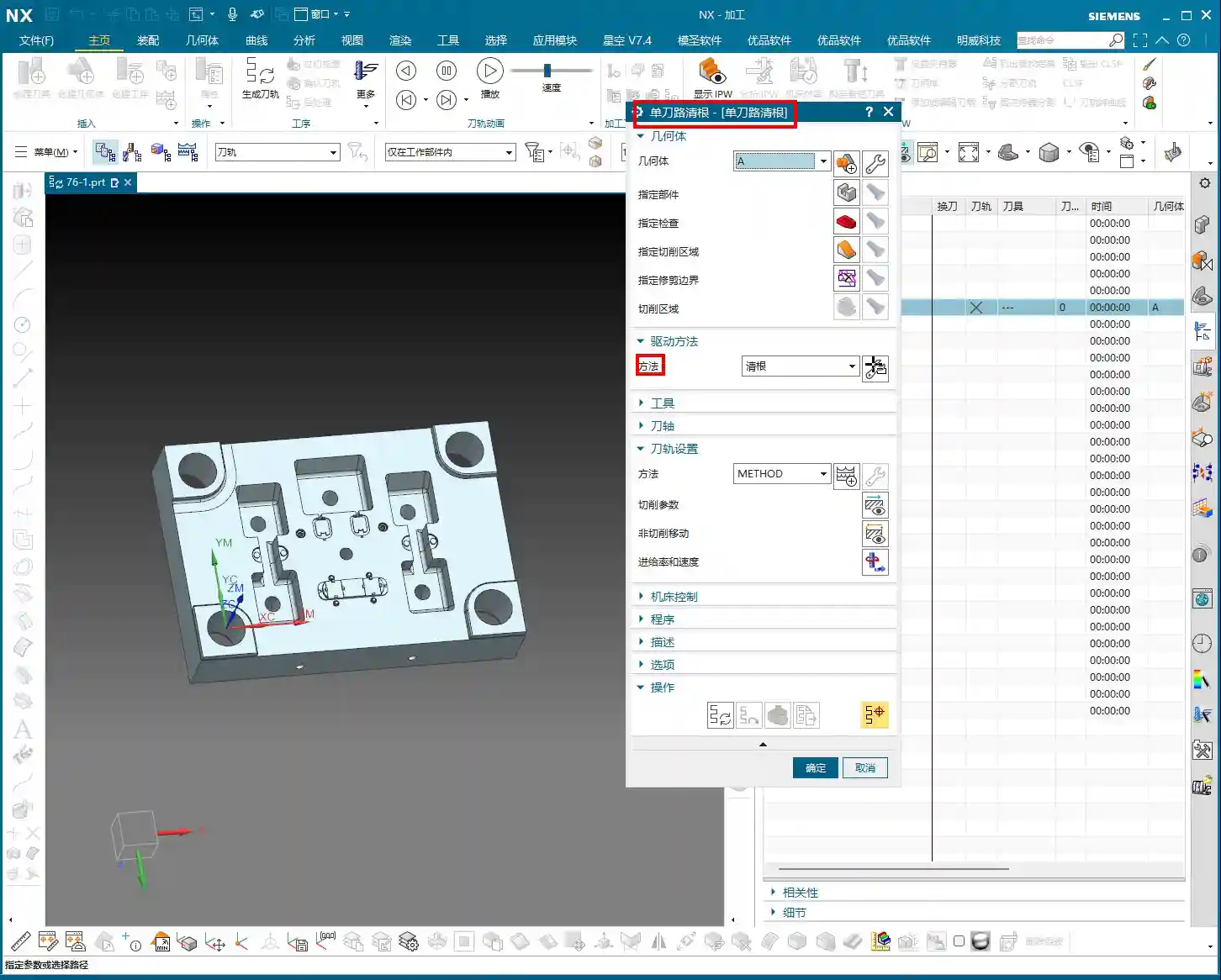
First, establish a Work Coordinate System (WCS). For its position, you can place it arbitrarily at the bottom; this is for practice, but in actual machining, precise positioning is crucial. Then, when inserting an operation, select today’s protagonist – Single Path Corner Cleanup.
The selection of the Part and Check Geometry goes without saying; this is fundamental. Make sure you select the correct part and fixtures to avoid tool collisions. For this example, let’s select workpiece A and confirm.

The “Déjà Vu” of the Corner Cleanup Page
Open the main page for this Corner Cleanup operation. Does it look familiar? Specify Part, Specify Check Geometry, Specify Cut Area, Specify Trim Boundaries… Aren’t these parameters almost identical to what we discussed earlier for Area Milling?
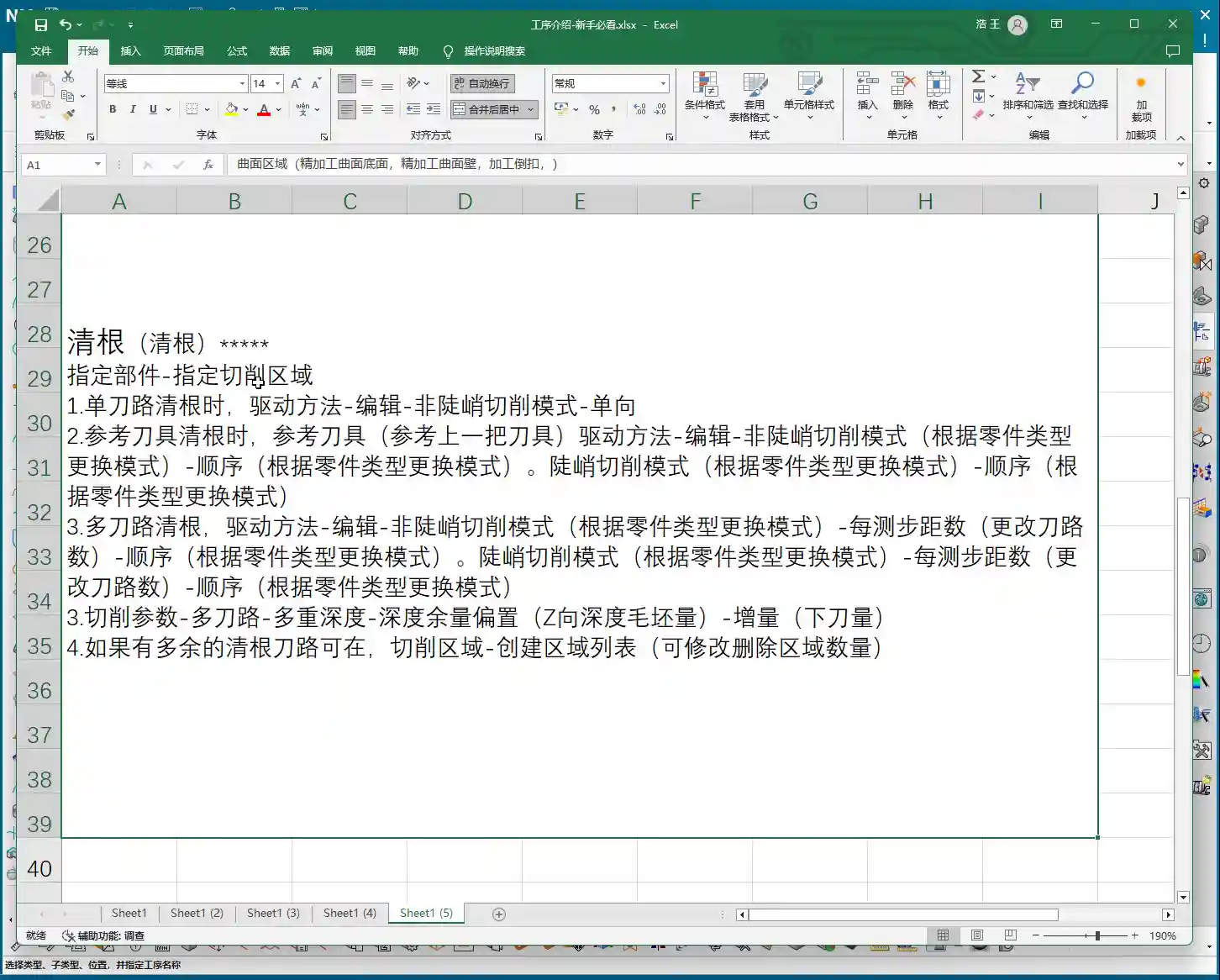
Exactly! This is a characteristic of Fixed Contour Milling. For these types of operations, most page layouts and parameters are generic. What truly determines whether it’s “Corner Cleanup or Area Milling” is the “Method” option. The method for Corner Cleanup operations is Clean Corner. Therefore, once you’ve learned the general logic of Fixed Contour Milling, learning these specific operations becomes much faster.
Core Secret: The “Neighbor Rule” for Cutting Region Selection
Here comes the main event! In Corner Cleanup operations, selecting the cutting region is where new users most often make mistakes, and it’s also the most critical step. Listen closely, this is a practical tip that textbooks don’t teach!
Essence of Selection: Don’t Just Select It, But Also Its “Neighbors”
Let’s take an example. Suppose you need to clean a fillet that is formed by the intersection of two faces. How do many new users select it? They directly click the fillet face, or the fillet edge, right? Completely wrong!
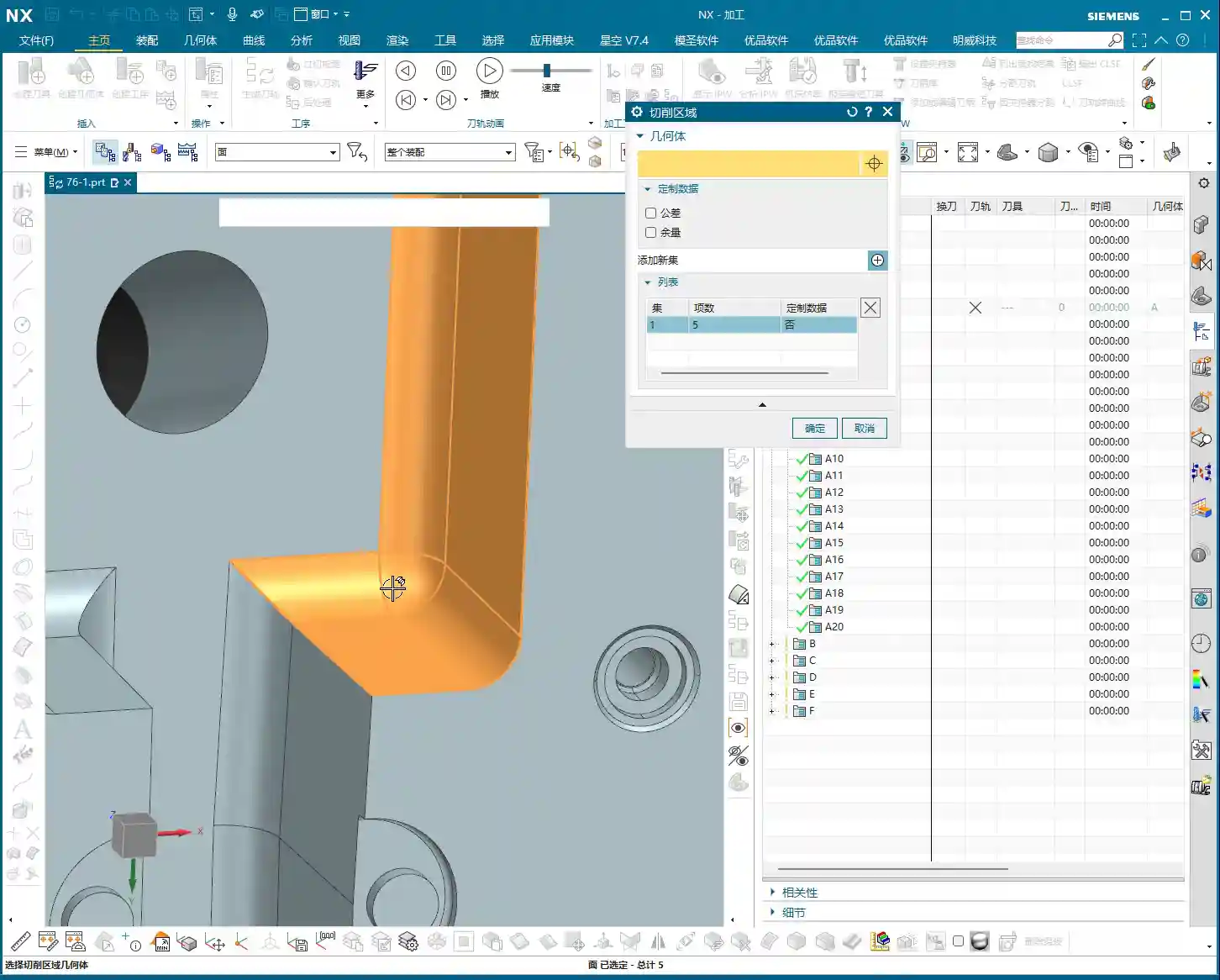
The correct approach is: You must not only select the “base” region you want to clean, but also select its adjacent “neighbor” faces! “Neighbors” refers to the faces that are directly connected to this fillet and form that corner. Selecting all of them ensures that Siemens NX correctly identifies the corner and generates a complete toolpath.

This logic is the same as what we discussed earlier for Rest Milling. Whenever the concept of a “reference tool” is involved, or the software needs to identify boundaries based on tool dimensions, you must follow this “Neighbor Rule.” Whether it’s selecting faces or selecting lines in Planar Profile Milling, as long as it’s linked to tool characteristics, you must select the adjacent regions as well. Otherwise, the toolpath will at best be incomplete, or at worst, it won’t be calculated at all, or it will be incorrect, which is a complete waste of your time!
UI “Trick”: The Yellow Line Pitfall – Don’t Fall for It Again!
After the toolpath is generated, you might see some yellow lines appear on the workpiece. Many new users immediately think, “Oh no, is my toolpath problematic? Why are they all yellow? The toolpath looks off!” They then panic and hit cancel, assuming the command isn’t working. STOP! Don’t panic!
Yellow Lines: Merely a “Display Issue”
Listen up, these yellow lines, they are not your toolpath, nor are they an indication of a toolpath error! This is simply a “display issue” or a “display characteristic” of the Siemens NX software. It’s just there to visually indicate that this area is your defined cutting region.
This has no actual machining significance, and it has absolutely nothing to do with your toolpath. It will not affect your actual cutting. If you don’t believe me, try it: After generating the toolpath, click “Replay”, and you’ll see the yellow lines disappear immediately, right? Or, click “OK”, close the file, reopen it, and check again – the yellow lines will have automatically vanished.
So, the next time you see these yellow lines, don’t assume the toolpath is wrong; the software is just playing a “little trick” on you. As long as you’ve selected the cutting region correctly and your tool parameters are in order, then confidently proceed, and don’t get misled by this minor detail.
Toolpath Analysis: The Essence of Single Path Corner Cleanup

Let’s generate the toolpath now, and then see exactly how it moves.
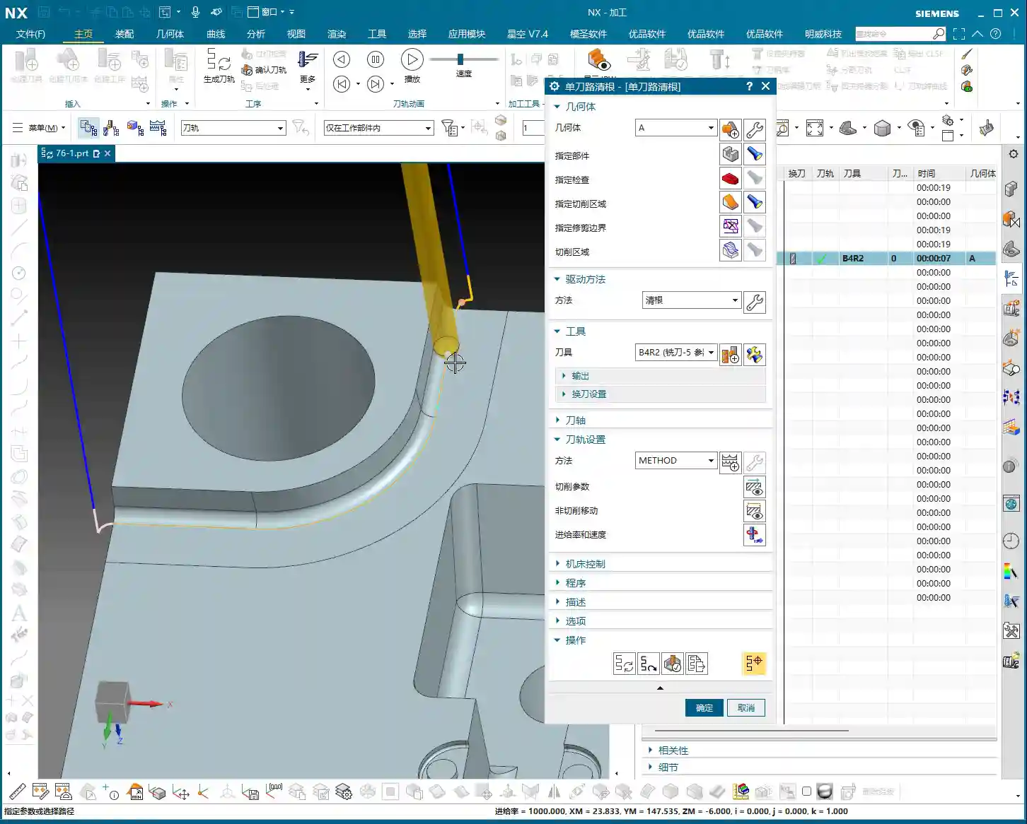
One Pass Along the Edge: The Core of Single Path Corner Cleanup
Look! Doesn’t the tool move tightly along the boundary of our specified region, making only one pass? This is the core characteristic of Single Path Corner Cleanup! It only makes one pass along the deepest part of the corner to remove residual material.
Therefore, when using Single Path Corner Cleanup, your tool radius becomes particularly important. It should exactly match the target fillet radius you intend to clean. For instance, if you want to clean an R2 corner, you must select an R2 ball end mill, ensuring the tool’s radius matches the workpiece’s fillet radius. This way, the tool can precisely follow the R-angle with a single pass, cleaning off burrs and residual material in one go. If your selected tool radius is incorrect, the result of this single pass will certainly be unsatisfactory, and might even leave new residual material.
Single Path Corner Cleanup is designed for precisely cleaning individual, well-defined fillet radii or base areas, aiming for the efficiency and accuracy of a single, perfect pass.
Summary: Pitfall Avoidance Guide
- Cutting Region Selection is Paramount: Don’t just select the target face; you must also select all “neighbor” faces adjacent to the target face. This is crucial for ensuring correct toolpath generation; otherwise, it’s easy to fail to calculate a toolpath or generate incorrect toolpaths, wasting valuable time.
- Yellow Lines are Merely a Display Issue, Not a Toolpath Error: When you see yellow lines appear after toolpath generation, don’t panic! It’s merely a visual cue from the software, unrelated to the actual toolpath, and not an error. The yellow lines will disappear after clicking “Replay” or “OK.”
- Tool Selection Must Match Fillet Radius: For Single Path Corner Cleanup, the selected tool’s corner radius should precisely match the radius of the fillet to be cleaned, ensuring a single, accurate cut and avoiding secondary modifications and accuracy deviations.
- Generic Logic of Fixed Contour Milling: The Corner Cleanup operation page is similar to other Fixed Contour Milling operations like Area Milling; the core difference lies in the “Method” option. Understanding this commonality will help you master Siemens NX machining programming faster.
- Practice Makes Perfect: Don’t just read theory; get hands-on, and observe the cutting sparks and actual results. Only then can you truly master these practical tips and wield Siemens NX with expertise.
“`
👤 About the Author:
The author is a veteran CNC machining professional with 15 years of industry experience, specializing in UG NX programming. This article is an original work representing personal practical insights.
⚠️ Copyright Notice: Unauthorized reproduction or distribution without prior communication is strictly prohibited.
Leave a Reply