Tag: NX Chamfering

  • UG/NX Fixed Contour Milling: Boundary Chamfer and 3D Chamfer Hardcore Practical Tutorial, Unlock the

    📝 Key Takeaways: Master Wang guides you step-by-step through UG/NX boundary and 3D chamfering programming, from part selection to parameter tuning, conquering challenges on inclined and curved surfaces. Practical insights on offset and stock control address common toolpath issues, making your chamfering process more precise and efficient. All the tips you won’t find in textbooks are right here!

    Master UG/NX Boundary Chamfering: From 2D to 3D, Master Wang Helps You Tackle Complex Issues

    Alright, newcomers, listen up! Today, Master Wang is going to talk to you about ‘Boundary Chamfering’ in UG/NX. Don’t underestimate it; this isn’t just for chamfering straight edges. It can handle chamfers on inclined surfaces, curved surfaces, and even complex sculptured surfaces. This is a common operation in our shop, different from purely theoretical textbook stuff. We focus on practical application, efficiency, and how to avoid pitfalls.

    In UG/NX, the ‘Boundary Chamfer’ function is incredibly powerful; it’s essentially an advanced application under ‘Fixed Contour Milling’. Unlike the ‘Planar Profile Milling’ chamfering we’ve learned before, ‘Planar Profile Milling’ can only process 2D chamfers on flat surfaces, and it’s useless for inclined or curved surfaces. But ‘Boundary Chamfer’ is formidable; it truly achieves what you often call ‘3D Chamfering’. So, from now on, when you encounter chamfers on complex shapes, don’t even think about forcing it with planar milling. It’s not only inefficient but also risks producing scrap!

    Core Operating Steps: Detailed Explanation of Boundary Chamfer (Fixed Contour Milling)

    Let’s dive right in, step by step. Remember, every step has a reason; don’t just click the mouse, understand *why* you’re clicking.

    Step One: Select the Chamfering Operation

    Navigate to our manufacturing module, select ‘Fixed Contour Milling’, then choose ‘Boundary Chamfer’ from the sub-type options. This can also be considered 3D Chamfering, and its capabilities are robust. Just confirm.

    Step Two: Part Selection (Crucial!)

    This is where many newcomers make mistakes! When selecting the part, NEVER select the entire component indiscriminately! We only select the faces that require chamfering, or, more precisely, just the chamfered surface itself. Why? Because this relates to ‘projection blank distance’ (or ‘projection boundary’). In multi-axis machining, especially complex surface machining, if you select everything, the software has to calculate the projection of the entire part, which can lead to messy toolpaths and unnecessary collisions. While less obvious in 3-axis, forming good habits here will save you a lot of trouble. So, just select the chamfered faces, got it?

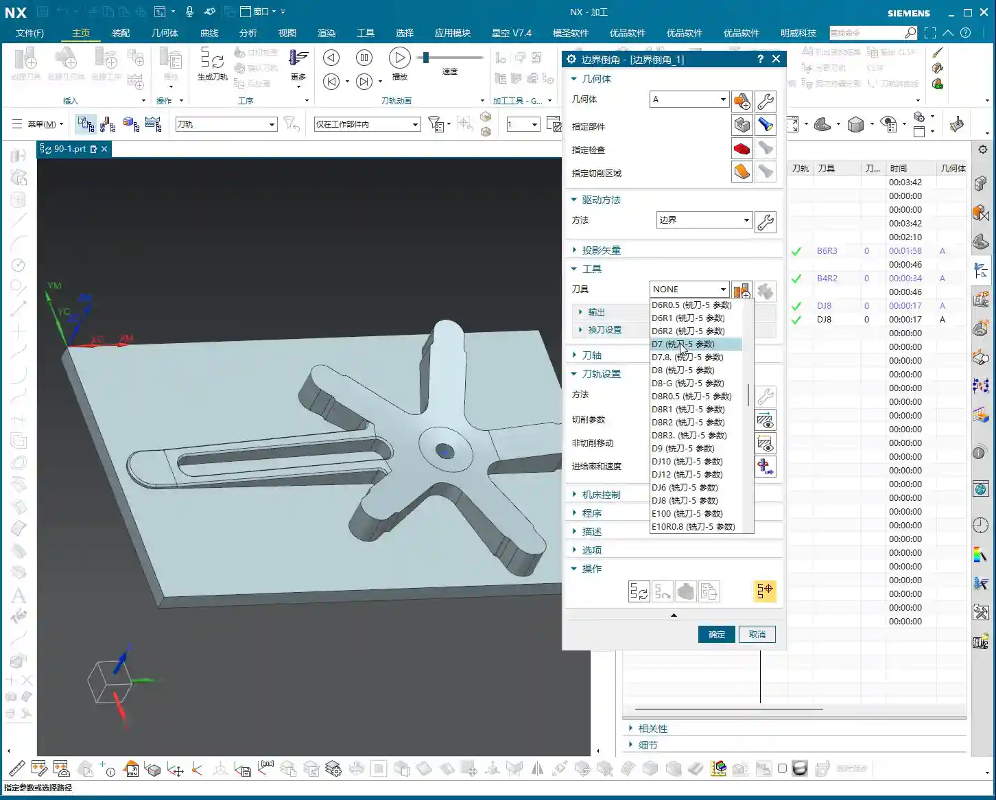
    Step Three: Tool Selection

    Nothing much to say here. Just select an appropriate ‘Chamfer Mill’. Pay attention to the tool’s tip radius and angle; they must match the chamfer specified in your drawing. For example, if you’re creating a C0.5 chamfer, you need to use the corresponding chamfer mill, don’t try to make do with a large corner radius end mill.

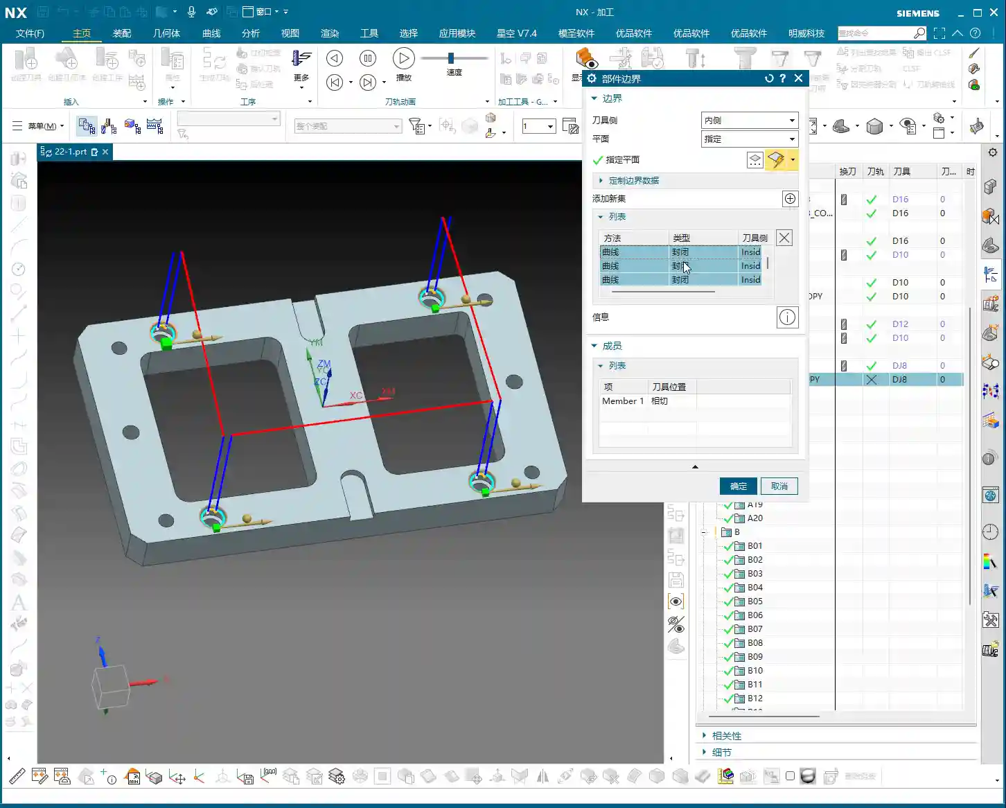
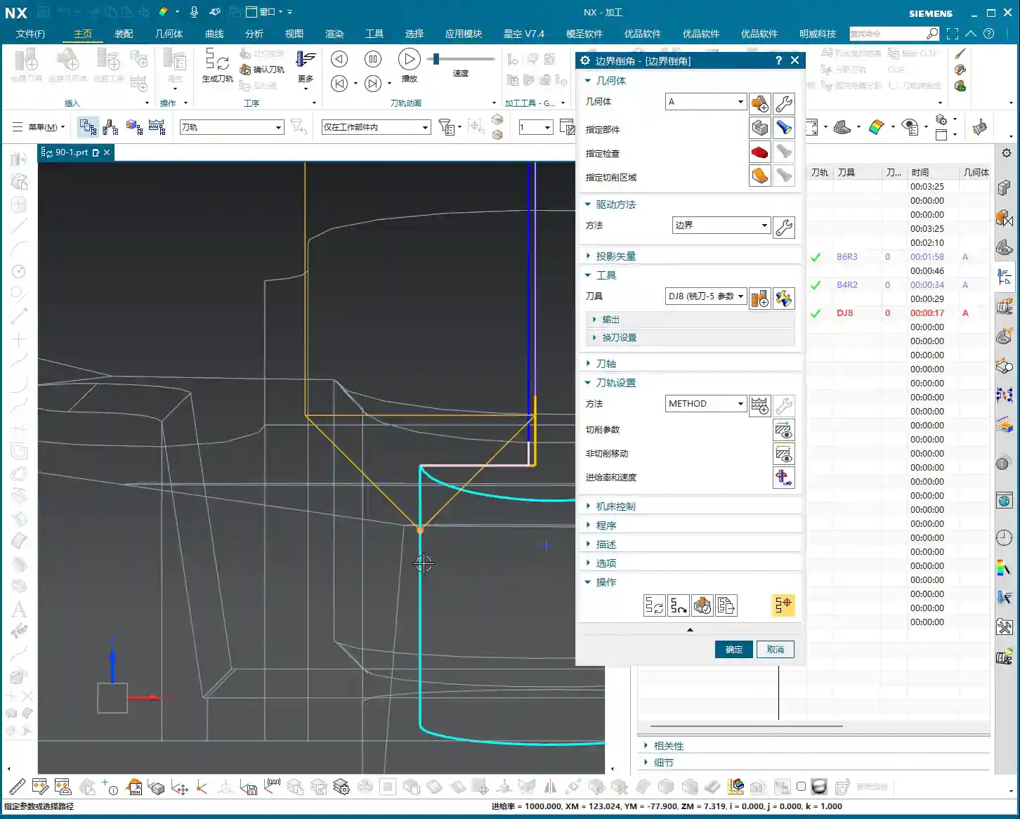
    Step Four: Drive Geometry (Key to Toolpath Generation!)

    This is the essence! Under ‘Drive Geometry’, we need to select the ‘inner’ boundary line of the chamfered area, which is the inner edge of the machining boundary. Mark my words: Only select the inner side! If you select the outer side, or the wrong edge, the toolpath will be completely off – at best, you’ll get an alarm; at worst, a tool crash. The software will make your chamfer mill’s tip or a specific reference point follow these selected lines. So, get the lines right, and you’ve got half the toolpath correct.

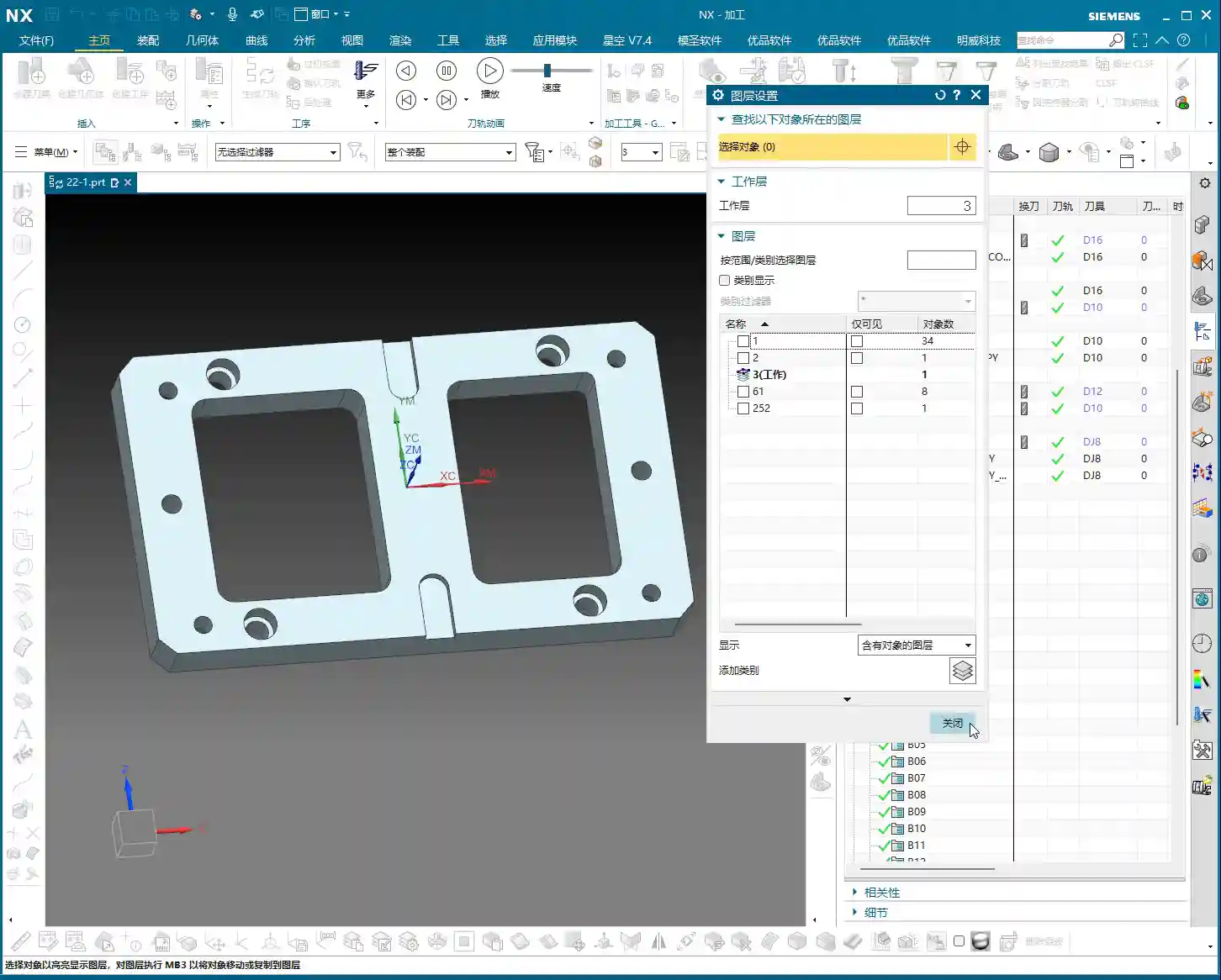
    Step Five: Projection Plane (Providing a Reference for the Toolpath)

    Specify any plane; for its height, it just needs to be above the part. This acts like a reference datum for the toolpath, projecting the selected drive geometry onto this plane and then generating the toolpath along that projected trajectory. Don’t overthink the exact height, just ensure it doesn’t interfere with the part.

    Step Six: Cut Side and Cut Method

    For ‘Cut Side’, we typically select ‘Outside’. This determines which side of the selected boundary line the tool will cut from. Since we’ve chosen the inner boundary, the tool cutting from the outside inwards will correctly machine the chamfer. For ‘Cut Method’, simply select ‘Chamfer’.

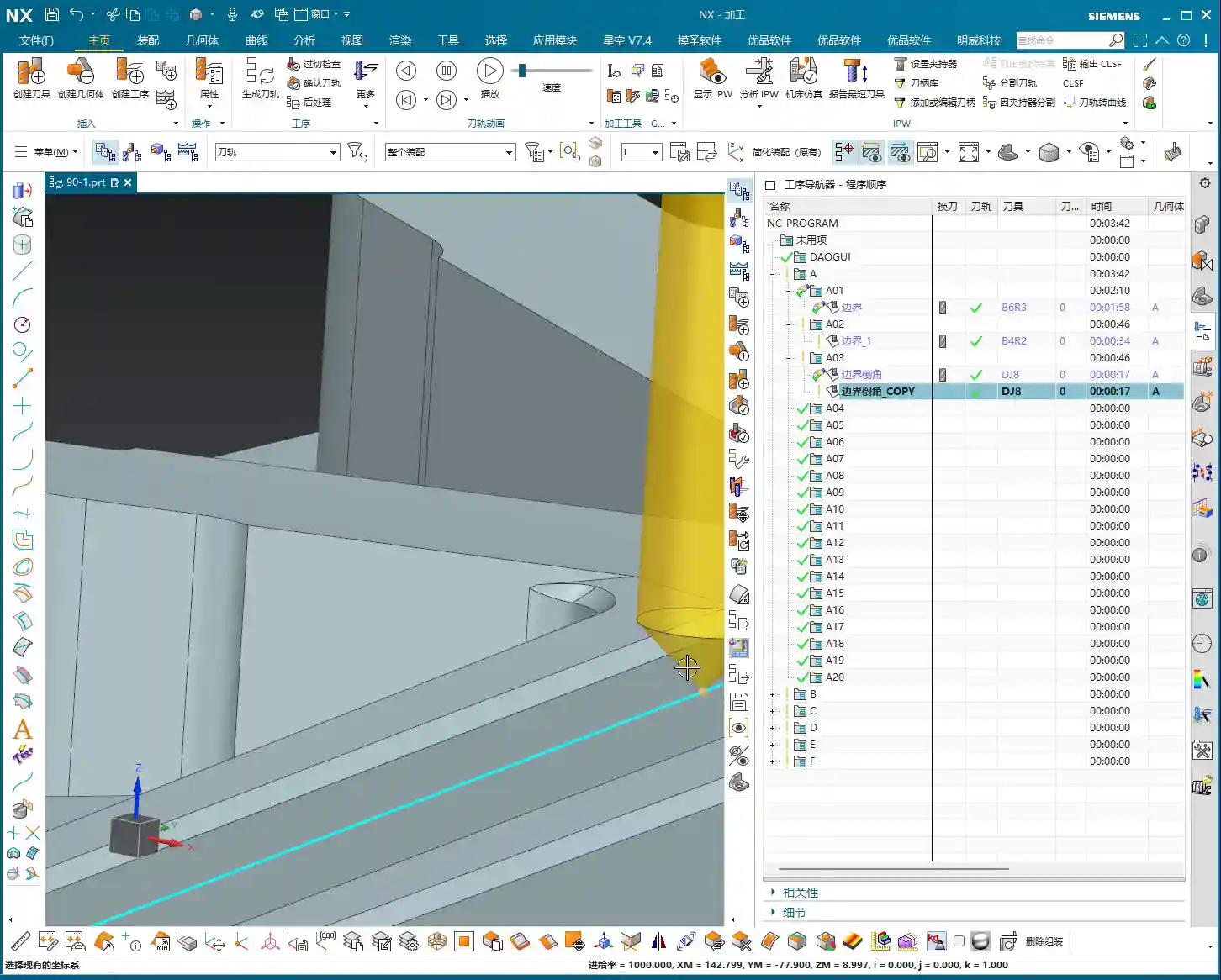
    Step Seven: Generate Toolpath

    Once everything is set, directly generate the toolpath and check the results. If you’ve followed my instructions in the previous steps, the toolpath should appear. If there’s an error or the toolpath looks incorrect, it’s most likely due to incorrect part selection or drive geometry.

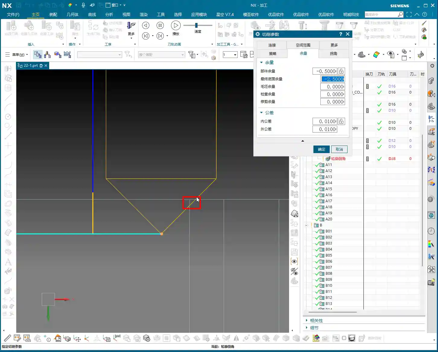
    Key Parameter Tuning: Precise Control of Chamfer Size and Position

    Having a toolpath isn’t enough; you also need precise control over the chamfer’s size and location. This requires parameter tuning, especially that ‘offset’ value.

    Tolerance

    Generally, you don’t need to change our machining tolerance; just keep the default values unless there are specific precision requirements.

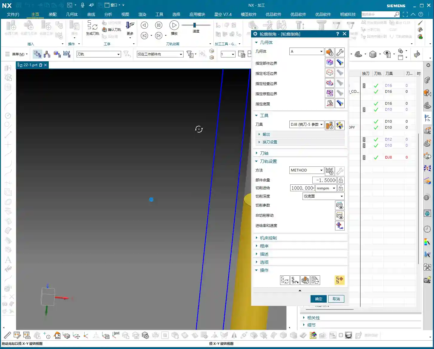
    Offset: The ‘Magic Wand’ for Chamfer Depth

    This ‘Offset’ parameter is the key to controlling our chamfer depth! Its default value is usually -2. What does this mean? It determines the offset of the chamfer tool’s ‘point’ (usually the tool tip or a specific reference point) relative to your selected drive geometry (the inner boundary line).

    • If you change it to -3, you’ll find the toolpath goes deeper, and the chamfer becomes larger. This is because a negative value means the tool offsets away from the boundary line (i.e., further into the material).
    • Conversely, changing it to -1 will make the chamfer shallower.
    • Selecting -4 will make it even deeper.

    Therefore, whether the chamfer is deep or shallow, flush with the edge or further in, it’s all controlled by this negative offset value. You need to precisely adjust it based on the actual chamfer tool angle and the R or C chamfer size you intend to create. Don’t just rely on software simulations; combine it with your actual tools and blueprint requirements. Experiment a few times to find the optimal value. These are all practical insights that textbooks rarely elaborate on.

    Stock: Auxiliary Control for Chamfering

    If you want to fine-tune the chamfer size slightly further, you can also work with the ‘Stock’ parameter. For instance, setting a 0.2mm stock allowance is like adding a 0.2mm ‘protective layer’ outside the chamfer toolpath. The toolpath will retract slightly, resulting in a slightly smaller chamfer. This is different from ‘Offset’; offset controls the tool’s position relative to the boundary, while stock provides a global offset for the entire toolpath. Use them in combination as needed.

    UG/NX Chamfer Toolpath Optimization and Pitfall Avoidance

    Messy Toolpaths? You Selected the Wrong Faces!

    As I mentioned before, if your toolpath generates chaotically or the software throws an error, 90% of the problem lies in the selection of the part and drive geometry. Especially if you’ve selected the entire part as the component, or chosen the outer boundary for drive geometry, the software can easily ‘get confused’ during calculation.

    Remember my words: Only select the faces to be machined as the component, and only select the inner boundary of the chamfer for the drive geometry! This is how you ensure a clear and accurate toolpath, avoiding unnecessary calculations and potential collision risks.

    How to Control the Start Point of the Cut?

    Sometimes you find the toolpath always starts cutting where you don’t want it to. What do you do? It’s actually quite simple. When you’re selecting the drive geometry, the first line you click on will usually become the toolpath’s starting point. So, if you want the tool to start from a specific location, begin your selection from that line. These are small tricks, but they can save you a lot of hassle when it matters.

    Don’t Just Look at Software Simulations, Watch the Cutting Sparks!

    No matter how realistic software simulations are, they’re still virtual. For us working in the shop, the ultimate judgment comes from the actual machine’s performance. Once the toolpath is generated and parameters are set, always be careful during the first machining run! Start with a small feed rate and slow speed for a test cut. Carefully observe the cutting conditions, the cutting sparks, and the dimensions of the machined chamfer. If it’s incorrect, stop the machine immediately and adjust the parameters. Remember, practice is the sole criterion for truth; your eyes and ears are more reliable than any simulator! This is the true ‘knowledge you won’t learn in textbooks’.

    Summary: Pitfall Avoidance Guide

    Alright, that concludes today’s hardcore practical session on UG/NX Boundary Chamfering and 3D Chamfering. Remember these key points, and I guarantee you’ll avoid many detours:

    • The Essence of Part Selection: Only select the chamfered faces; don’t bite off more than you can chew, preventing toolpath chaos.
    • The Secret of Drive Geometry: Always select the inner boundary line of the chamfered area; this is fundamental to the toolpath’s direction.
    • The Magic of the Offset Parameter: Effectively use negative offset values to precisely control chamfer depth and tool position; this is the key adjuster for chamfer size.
    • The Role of the Projection Plane: Set a plane above the part as the toolpath projection datum; no need to overthink the exact height.
    • Practicality First, Shun Theoretical Talk: Software simulation is only a reference; the final result depends on actual machine cutting. Haste makes waste; observe cutting sparks and actual results closely, and adjust promptly.

    This boundary chamfer command, while having many interface parameters, only uses a few regularly. In my personal experience, this function is used extensively in actual machining; it’s extremely practical. Go and study it thoroughly, and if you have any questions, come ask Master Wang!

    👤 About the Author:
    The author is a veteran CNC machining professional with 15 years of industry experience, specializing in UG NX programming. This article is an original work representing personal practical insights.

    ⚠️ Copyright Notice: Unauthorized reproduction or distribution without prior communication is strictly prohibited.

  • Master Wang’s Practical Guide to Siemens NX Planar Profile Chamfering: From Beginner to Expert, with

    📝 Key Takeaways: Master Wang walks you through Siemens NX planar profile chamfering. From parameter settings to tool selection, this guide provides an in-depth analysis of the practical secrets behind “Allowance” and “Final Bottom Allowance,” teaching you how to precisely control chamfer size and tool cutting point to prevent tool chipping and improve machining efficiency.

    Hello everyone, Master Wang here. Today we’re continuing our discussion on NX machining, focusing on the chamfering function within Planar Profile Milling. This might seem straightforward, but there are a lot of hidden intricacies, especially with the parameter settings. One wrong step, and you’ll scrap your tool and ruin the job. Listen up – today, I’m going to share all the practical tricks you won’t find in textbooks.

    I. Core Chamfering Operation Workflow

    When doing any machining operation in NX, we generally follow a “three-step” strategy: Select Geometry, Select Tool, Generate Toolpath. Chamfering is no different, but success lies in the details.

    1.1 Geometry Selection: The Mystery of Top and Bottom Faces

    Let’s open the “Profile Chamfer” function. First, you need to tell the software which edge to chamfer. Typically, we select the edge or curve that requires chamfering.

    There’s a common, oft-repeated question here, but it’s especially crucial for chamfering: the software will ask you to select “Top Face” and “Bottom Face”. Listen up: when performing planar profile chamfering, “Top Face” and “Bottom Face” actually refer to the same face – the plane where your chamfer feature is located. For instance, if you’re chamfering a hole on a flat plate, just select the top face of the plate for both the top and bottom faces. Don’t overthink it; unlike deep cavity milling which requires an actual bottom face, chamfering is primarily based on a single edge.

    • Select Edge: For example, the edge of a round hole, or the outer boundary of a planar profile.
    • Specify Plane: Select the plane containing the edge you want to chamfer. For profile chamfering, both the upper and lower planes can typically be the same.

    1.2 Chamfer Tool Selection and Custom Creation

    Naturally, you’ll need to select a Chamfer Mill. The NX tool library usually includes common chamfer mill sizes like D6, D8, D10, D12 (all in mm). Choose the appropriate tool based on your workpiece size, chamfer dimension, and machine spindle taper.

    If your tool library doesn’t have the specific size you need—for example, if you want a D14 (mm) chamfer mill, or if the tip radius or angle doesn’t meet your requirements—then create one yourself! Don’t be afraid of the hassle; doing it yourself ensures you have what you need and deepens your understanding of tool geometry. When creating it, pay attention to these parameters: tool diameter, tip radius, chamfer angle, flute length, and overall length. Not a single one of these parameters can be wrong, or your generated toolpath will be useless.

    II. Key Parameter Analysis: Controlling Chamfer Depth and Position

    Parameter settings are the soul of chamfering. Other parameters like Depth of Cut (DOC) and Stepover have been discussed extensively before, so I won’t repeat them here. Today, we’ll focus on two critical parameters that determine chamfer quality: Allowance and Final Bottom Allowance.

    2.1 Allowance: The Determinant of Chamfer Size

    Within the “Cut Parameters,” there’s a setting called Allowance. Listen up: this is the key to controlling the final chamfer size!

    • Core Rule: To get a chamfer of a certain size, enter that value as a negative number!
    • Must be a negative value: For example, if you want a 0.5mm chamfer, set the Allowance to -0.5mm. If you want a very small chamfer just for deburring, say 0.1mm, then set it to -0.1mm.

    The meaning of this “negative value” can be understood as the offset of the tool’s centerline relative to the profile edge. A negative value means the tool will cut into the material. Therefore, this Allowance value directly determines the size of your chamfer. For instance, if you input -0.1mm, you’ll get a small chamfer, mainly for deburring; input -2.5mm, and the chamfer will be significantly larger.

    Master Wang’s Tip: Often, especially when machining high-volume parts, you only need to deburr slightly to save time and reduce costs. In such cases, setting the Allowance to -0.1mm or -0.2mm is perfectly suitable. Chamfer all holes and edges with this value to both ensure surface quality and boost efficiency.

    2.2 Final Bottom Allowance: The Secret to Tool Cutting Point Position

    This parameter is found under “Adjust Parameters.” It determines which part of the chamfer tool’s cutting edge will engage the material. This is a critical “pitfall” to avoid!

    As we all know, the tip of a chamfer tool is typically quite fragile. If it directly engages in heavy cutting, it’s very prone to chipping, which impacts tool life and machining quality. Therefore, we generally want the chamfer tool to cut with its side edge or a more robust part of the tool.

    • Parameter Meaning: Setting it to a negative value indicates the depth of the chamfer tool’s tip relative to the machined edge.
    • For example:

      • Assume you’re using a D8 (mm) 45-degree chamfer mill with a tip radius of 0. Theoretically, its cutting edge from the tip to the outer diameter is 4mm.
      • If you set the Final Bottom Allowance to -2.5mm (this is a common default value in my templates), it means the tool tip will be 2.5mm below the edge being chamfered. This allows the tool to cut with its side edge, significantly reducing the risk of tip chipping and leading to more stable machining.
      • If you set it to -1mm, the tool tip is closer, and the cutting point is nearer to the tip, which can cause problems.
      • If you want the chamfer to engage the “middle” of the tool’s cutting edge, for example, to create a 0.5mm chamfer, you might need to set it to -2.25mm. This value requires fine-tuning based on the actual geometry of your chamfer tool (e.g., effective cutting length).

    Master Wang’s Tip: The more negative this parameter is set (e.g., from -2.5mm to -3.5mm), the further the cutting point moves towards the more “robust” part of the tool, away from the tip. Conversely, the less negative (e.g., from -2.5mm to -1mm), the closer it gets to the tool tip. Unless you have specific requirements, it’s generally recommended to set a relatively deep negative value (such as -2.5mm or -3.5mm). This keeps the tool tip “out of the way,” allowing the tool’s side edge to perform the chamfering, which results in more stable machining and longer tool life. Don’t just rely on software simulations; observe the cutting sparks and listen to the cutting sound. Those are the real-world feedbacks!

    III. Practical Tips and Pitfall Guidance

    3.1 Handling Discontinuous or Multi-Segment Chamfers

    If the profile you’re chamfering consists of multiple discontinuous segments, or if you only want to chamfer specific segments, you’ll need to use the “Add New Set” function. When selecting geometry, after selecting each curve that needs chamfering, click Add New Set, and then select the next curve. This way, the software can combine these independent curves to generate a unified chamfer toolpath.

    3.2 Pitfalls of Chamfering Small Holes

    Chamfering small holes is particularly prone to problems. The core issue is matching the tool size to the hole diameter. If your chamfer tool is too large, or if the chamfer dimension is set too large, the tool might not be able to enter the hole, or it might collide inside the hole. A simple rule: the chamfer tool’s radius (R_tool) plus the chamfer dimension (C) must be less than or equal to the hole’s radius (R_hole), i.e., R_hole ≥ R_tool + C. Otherwise, you’ll either fail to create the chamfer, make the hole too large, or even cause a tool crash! In such cases, you either need to switch to a smaller chamfer tool or reduce the chamfer dimension.

    3.3 Minor Display Bugs in NX Interface

    Many beginners encounter this situation: you’ve copied a chamfer operation, modified the geometry, and generated a toolpath, but the screen still shows the toolpath from the original operation. You might think the change didn’t take effect, but it actually did; the software’s display is just a bit “sluggish.”

    The solution is simple: simply click the mouse anywhere in an empty space within the NX graphics window, or switch to another view and then switch back. The old “ghost” toolpath will disappear, and the new one will display correctly. These are just minor quirks of the software; get used to them, and don’t let them make you tear your hair out.

    3.4 Impact of Material Properties on Chamfering

    Different materials present different chamfering effects and difficulties:

    • Aluminum: Easy to cut, but prone to burr formation. Cutting parameters must be optimized to avoid excessive material removal leading to burrs.
    • Stainless Steel, Titanium Alloys, High-Temperature Nickel-Based Alloys: These materials have high hardness and toughness, generating significant cutting forces, which can lead to accelerated tool wear. When chamfering, use a high-rigidity machine, reduce cutting speed, appropriately increase feed rate, select coated carbide chamfer mills, and ensure ample coolant. Don’t force it; tools cost money!

    Summary: Pitfall Guide

    1. Geometry Selection: The top and bottom faces are usually the same plane—the one containing the edge you’re chamfering. Don’t overcomplicate it.
    2. Chamfer Size Control: The “Allowance” parameter must be a negative value; its absolute value is the chamfer dimension. For example, -0.5mm means a 0.5mm chamfer.
    3. Tool Cutting Point: “Final Bottom Allowance” controls the tool’s cutting position on its edge. Aim for a deeper negative value (e.g., -2.5mm, -3.5mm) to prevent the tool tip from direct cutting, thus protecting the tool.
    4. Small Hole Chamfering: The tool must “fit” into the hole! Ensure Hole Radius ≥ Chamfer Tool Radius + Chamfer Dimension. Otherwise, change the tool or adjust the chamfer size.
    5. NX Display Bug: Toolpath not refreshing? Just click the mouse in an empty space to refresh the interface.
    6. Practical Experience is King: Don’t just rely on theory. In actual machining, observe cutting sparks and listen to cutting sounds. Adjust parameters based on real-world conditions. Machining parameters are dynamic, not static!

    Alright, that’s all for today’s planar profile chamfering discussion. These are all insights gained from my fifteen years in the trenches, and I hope they prove useful to you. Work diligently, think critically, and you’ll avoid many detours!

    👤 About the Author:
    The author is a veteran CNC machining professional with 15 years of industry experience, specializing in UG NX programming. This article is an original work representing personal practical insights.

    ⚠️ Copyright Notice: Unauthorized reproduction or distribution without prior communication is strictly prohibited.