📝 Key Takeaways:
NX Complex Rib Programming: A Practical Deep Dive into a Three-Stage Process
Alright, Listen Up, Lads! Master Wang Teaches You Three Tricks to Ace Rib Machining
Today, we’re not talking theory; we’re getting straight to the practical insights. All that theory you learned in school often leaves you stumped on the shop floor, especially with parts like these ribs that demand both strength and precision. Don’t worry. Today, Master Wang will walk you through this case study, showing you how to program efficient and precise toolpaths using Siemens NX. Remember, machining isn’t just theory; it’s about watching the cutting sparks and listening to the machine!
Don’t let the simple structure of these ribs fool you; they’re often the backbone of a part, demanding high strength and precision. Especially those small fillets and chamfers at the connections—mishandle them, and you’ll either compromise assembly or create stress concentrations, leading to immediate scrap. That’s why Master Wang has put together a “Three-Stage” programming method that’s guaranteed to be effective and immediately applicable!
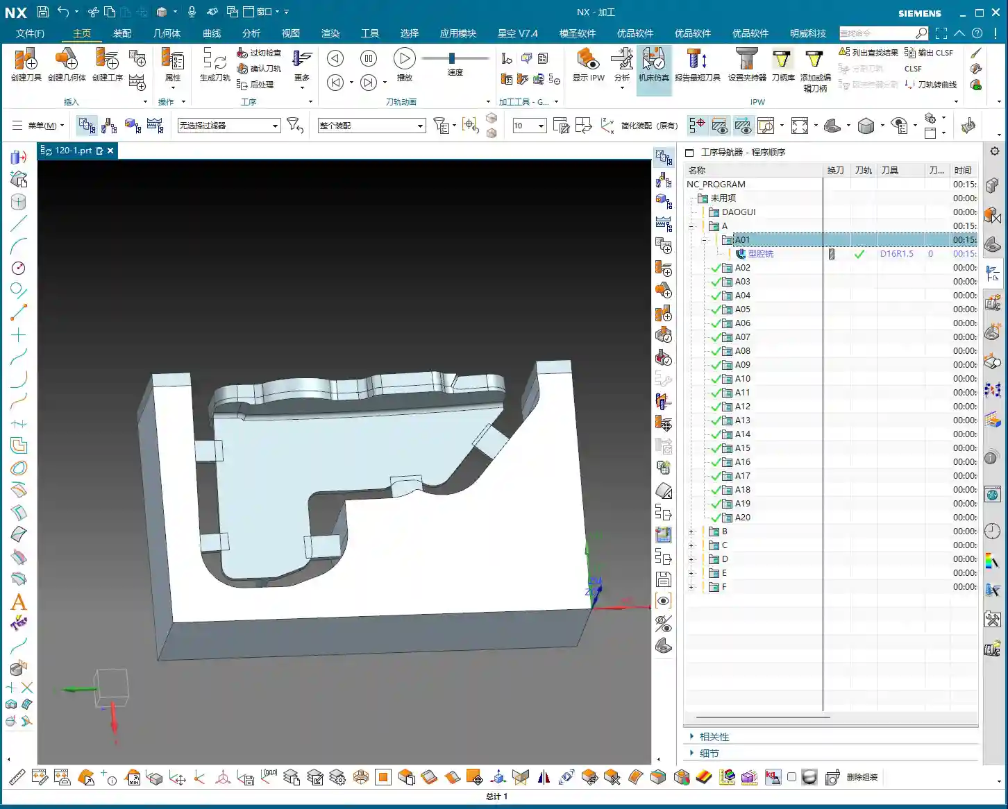
Stage One: Rib Side Wall Roughing / Semi-Finishing – “Aggressive Yet Controlled, Step by Step”
This is the first, and most crucial, step. The side walls of the rib are often the primary load-bearing surfaces and must be smooth and flat. We need to start with a larger tool to Contour Mill out the basic shape.

Core Operation: Cleverly Use Surface Milling, Avoid Ball End Mill Pitfalls
Listen up, here we’re using “Surface Milling”. Why Surface Milling? Because it’s highly adaptable to complex surfaces, creating smoother toolpaths and uniform cutting forces. Some novices see a sloped surface and immediately think of using a ball end mill – a huge mistake! When machining side walls with a ball end mill, the cutting action occurs at the tool’s bottom, leading to low cutting efficiency and prone to Chatter. Especially when the bottom fillet hasn’t been cleared yet, a ball end mill simply can’t reach, failing to “Contour Mill to the bottom surface.”
- Tool Selection: I typically choose a D12R1.5 (diameter 12mm, 1.5mm corner radius) flat end mill with a radius. Don’t underestimate this corner radius; it significantly boosts tool strength, preventing chipping at the tip, and also simplifies Corner Cleanup in subsequent operations.
- Infeed and Cutting Parameters:
- Depth of Cut: If it’s aluminum, you can go with a 0.15mm Stepdown per pass. Don’t get greedy; we’re not chasing speed, we’re laying the groundwork for the Finishing pass.
- Cutting Pattern: Use “Zigzag” to reduce retracts and improve efficiency.
- Stock Allowance Control: Leave 0.2mm on the side walls and 0.3mm on the bottom surface. These allowances are for subsequent Finishing passes and Corner Cleanup; don’t machine them all off in one go.
- Boundary Selection: Precisely select the side wall surfaces to be machined. As for those small fillets, leave them for now; we’ll tackle them in Stage Two.
Master Wang’s Tip: Software simulations look great, but ultimately, it comes down to the cutting sparks and sound from the machine. If the sound is dull, it indicates excessive cutting force, possibly due to too fast a feed rate or too large a Depth of Cut – you need to adjust it! Excessive sparks suggest tool wear, which also needs attention.

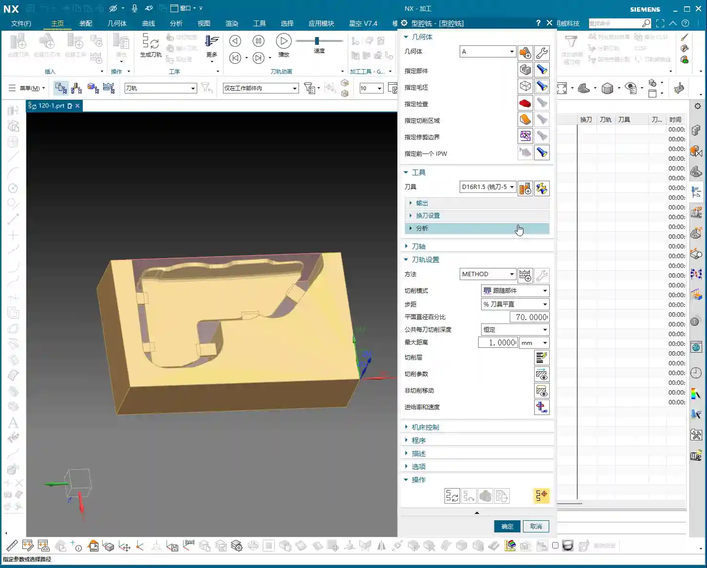
Stage Two: Cavity Roughing and Local Finishing – “Progressive Refinement, Fine Detailing”
Stage One covered the main outline of the rib. Now it’s time to tackle the hidden cavities and fillets, which are critical for precision and surface quality.
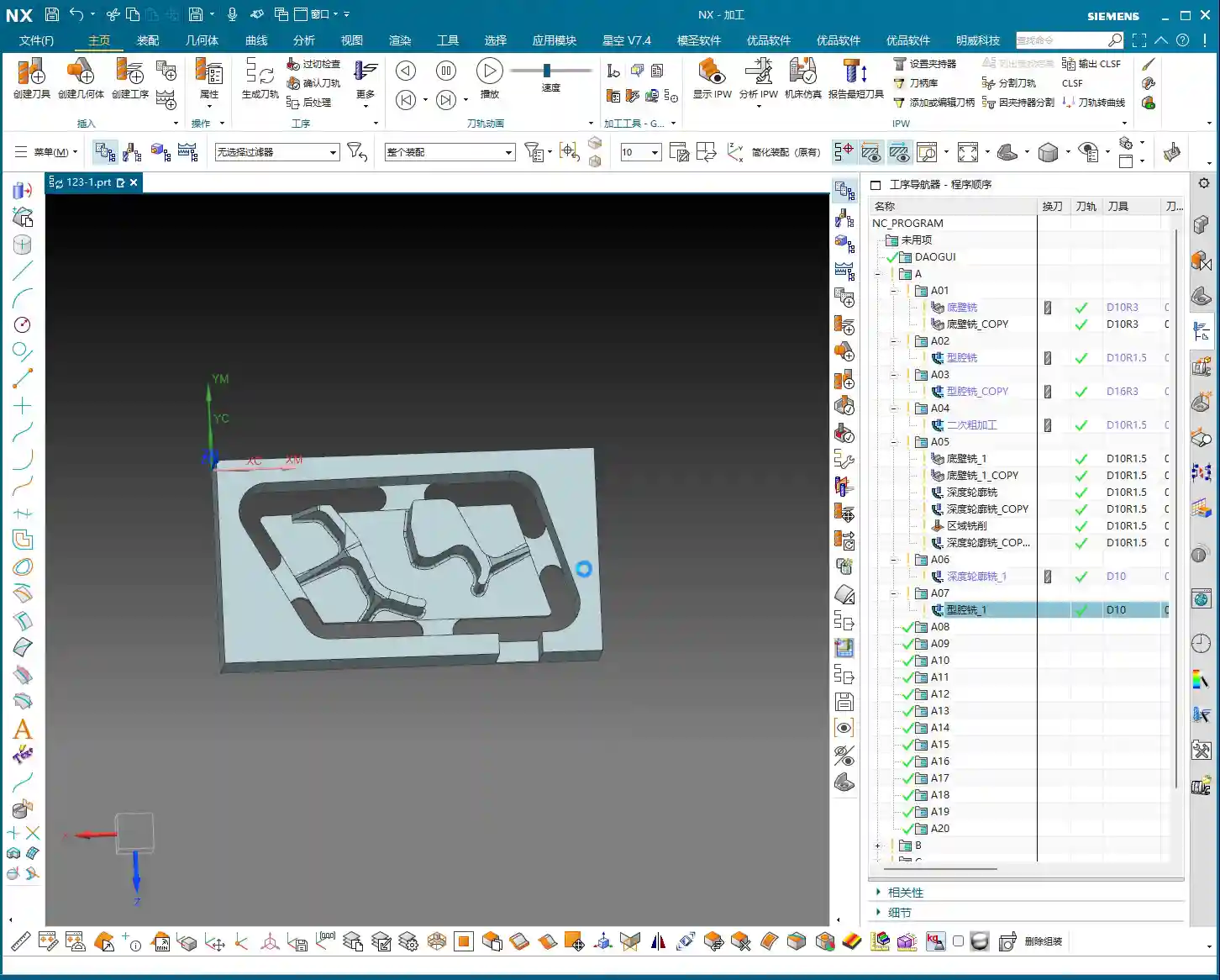

Core Operation: Utilize Deep Contour Milling and Cavity Milling Concurrently for Thorough Fillet Cleanup
This stage consists of two parts: roughing first, then finishing, with targeted strategies.
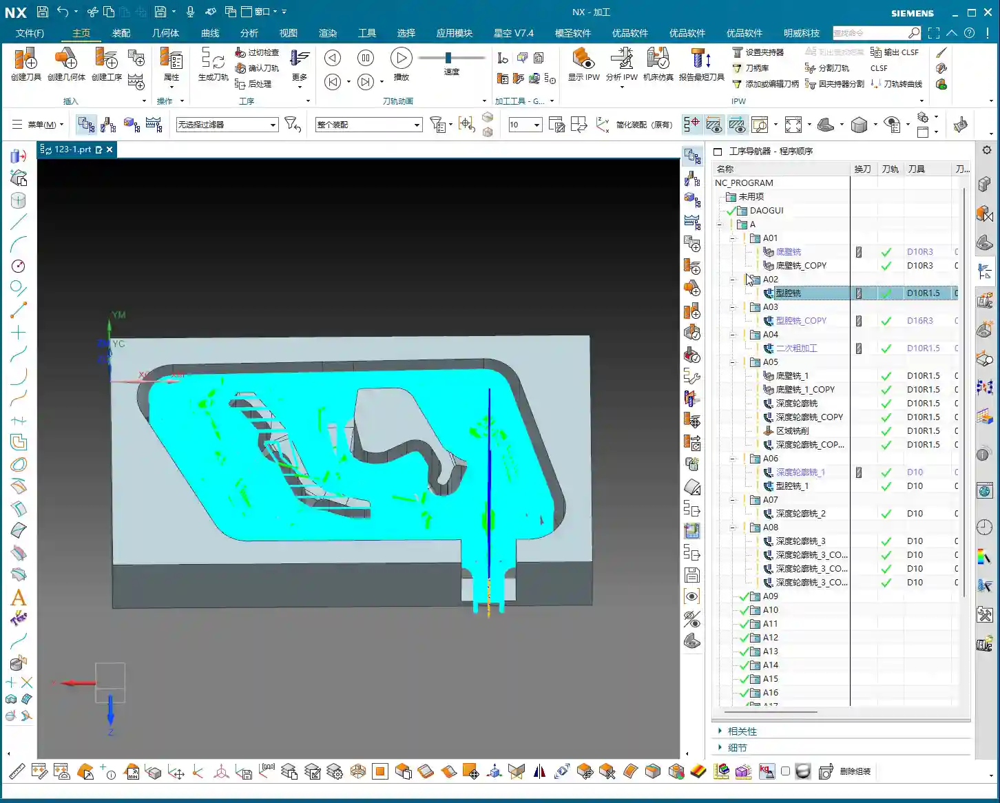
- Cavity Roughing (Main Area):
- Operation Type: We’ll use “Cavity Milling for Roughing”. For material removal in the areas beneath the rib or the main body, cavity milling offers the highest efficiency.
- Tool Selection: You can still use the previous D12R1.5 tool, or switch to a larger diameter tool depending on the cavity size.
- Cutting Parameters: Use a 0.5mm Depth of Cut per pass, a side wall allowance of 0.1mm, and set the bottom allowance to 0 this time (as it’s managed internally by the cutting levels), ensuring thorough roughing without overcutting.
- Depth Control: Start from the top surface of the rib and mill down to the final bottom surface. Remember to leave a 0.1mm machining allowance to prevent milling into the workholding table and to provide room for the Finishing pass.
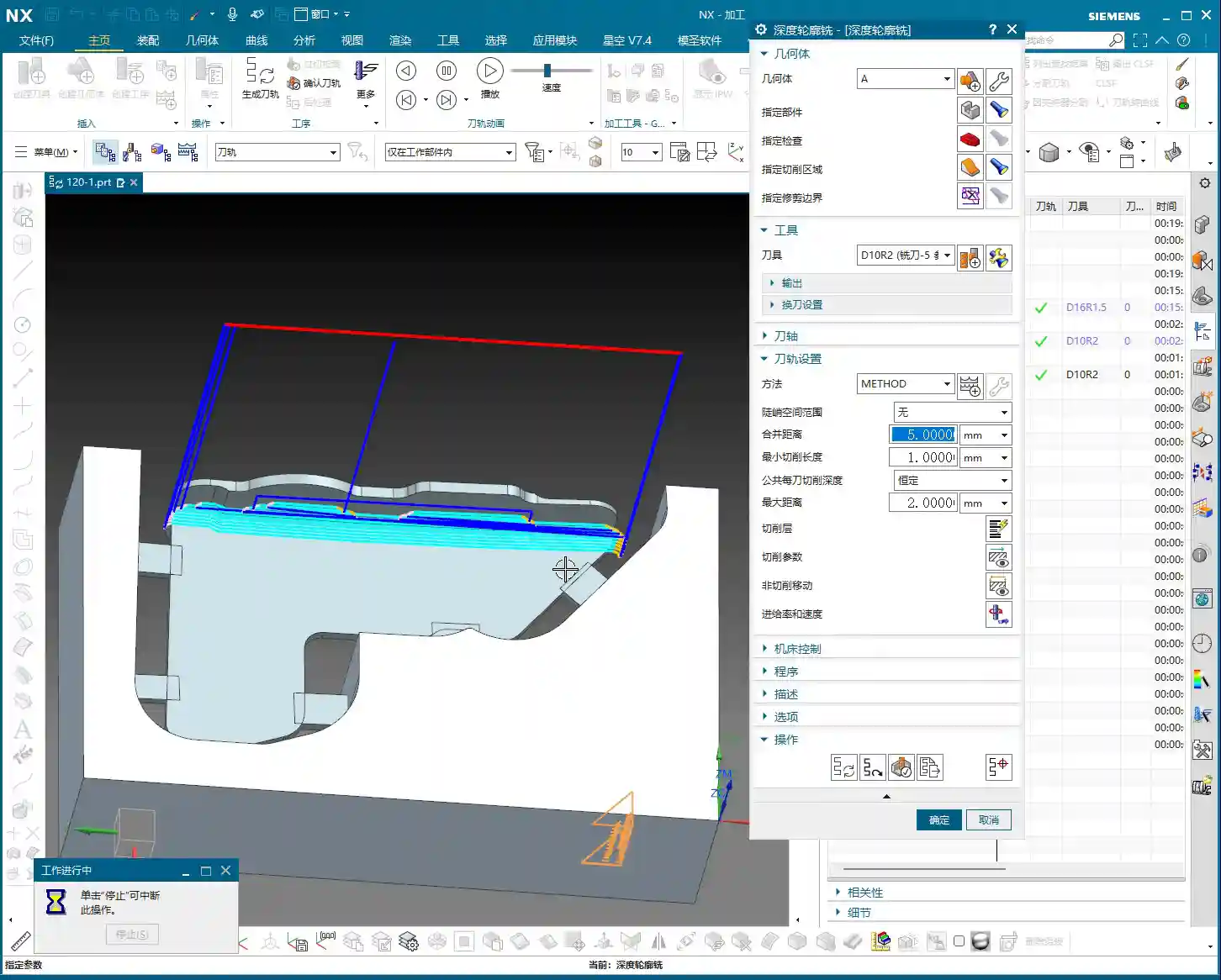
- Local Fillet Finishing (Corner Cleanup):
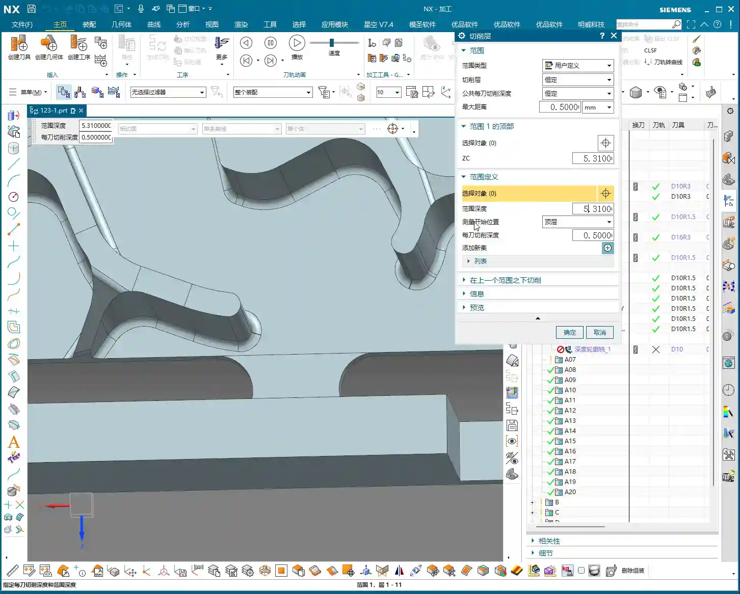
- Operation Type: The core operation is “Deep Contour Milling”, specifically for Corner Cleanup. It performs multi-level cutting along the part’s contour, making it ideal for internal radii.
- Tool Selection: Switch to a smaller ball-nose end mill, for instance, a D6R0.5 or D4R0.2. Determine this based on the minimum fillet radius of the rib; the tool diameter must be less than or equal to the minimum fillet diameter.
- Cutting Parameters: Use a 0.5mm Depth of Cut to ensure stable cutting. Most importantly, precisely control the start and end surfaces, beginning from the bottom surface of the rib, adding the fillet radius as the start height, and milling to the target height.
- Allowance: Set both side wall and bottom allowances to 0; this pass is about milling it precisely to size, ensuring thorough Corner Cleanup.
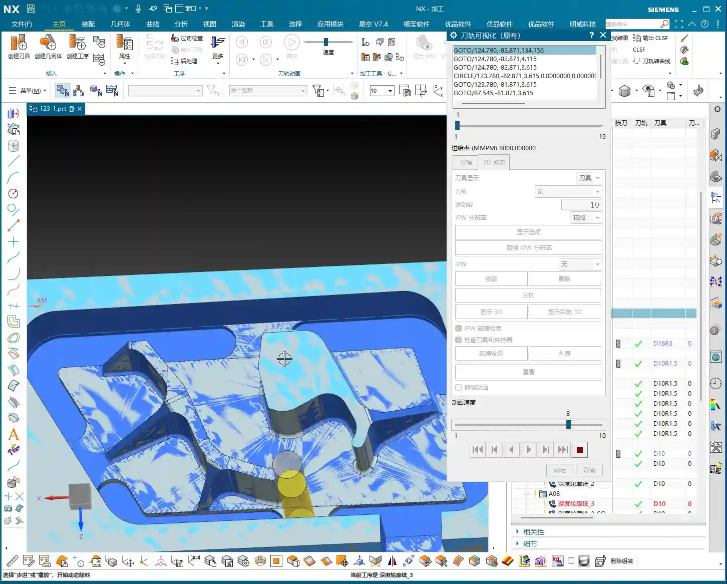
Master Wang’s Tip: When using Deep Contour Milling in complex areas, you might sometimes encounter “Chatter” or “tool skipping” phenomena. If this happens, try reducing the feed rate or adjusting the cutting strategy, for example, from “Conventional” to “Climb Milling.” Don’t be afraid to go slow; stability and precision are paramount.

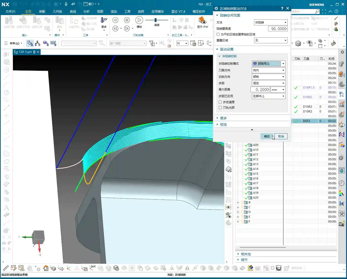
Stage Three: Contour Finishing and Final Cut-Off – “A Single Pass for Perfection, The Grand Finale”
The first two stages have largely taken care of the rib’s forms and internal features. This final stage is about giving the part its “outer finish” and cleanly “liberating” it from the raw stock.
Core Operation: Smooth Side Walls, Precise Cut-Off, Leave a “Tab”
This step is crucial for the final surface quality and the integrity of the part; don’t mess it up.
- Rib Side Wall Finishing Pass (Smooth Side Walls):
- Operation Type: Continue using “Deep Contour Milling”, as it allows for a precise Finishing pass across the entire side wall, ensuring surface finish.
- Tool Selection: We’ll use a D10R0.5 ball-nose end mill to ensure the required surface roughness.
- Cutting Parameters: Use a 1-2mm Depth of Cut, or even go full depth in one pass, to achieve the best surface finish. From the top surface to the bottom, control the final depth by subtracting a 0.7mm allowance.
- Allowance: Set both side wall and bottom allowances to 0; this is the final Finishing pass, so no more allowance should be left.
- Final Contour Cut-Off:
- Operation Type: We’ll still use “Deep Contour Milling”, but this time, it’s to cut the part free.
- Tool Selection: Continue with the D10R0.5 or a D10 flat end mill, depending on the requirements for the cut-off surface.
- Cutting Parameters: Use a 0.2mm Depth of Cut, follow the outer contour, and ensure the cutting depth penetrates the part, but be careful not to cut into the Fixturing.
- Cut-Off Allowance: Here’s the most important part: leave a 0.5mm connection (or even smaller) at the bottom for easy manual break-off or wire EDM later. This is called a “tab”; don’t cut through it completely, or the part will drop, potentially getting dinged or seriously damaged.
Master Wang’s Tip: For this cut-off step, once the program is ready, be sure to carefully inspect the toolpath on the machine, especially the safety clearance between the tool and the Fixturing. Don’t let the tool hit the Fixturing before it even touches the part – that’s more than a minor issue!
Summary: Pitfall Avoidance Guide
- Tool Selection Pitfalls: Don’t always try to use one tool for the entire job. Use larger tools for Roughing, and smaller tools for Finishing passes and Corner Cleanup. Flat end mills, radius end mills, and ball end mills each have their strengths; choose flexibly based on the geometry of the machining area, don’t cut corners.
- Stock Allowance Control Errors: Leave sufficient allowance for Roughing, and gradually reduce it for Finishing passes. Incorrect allowance can lead to rapid tool wear or failure to meet surface requirements. Especially during cut-off, always leave a “tab” at the bottom to secure the part.
- Blind Cutting Parameter Selection: Feed rate, spindle speed, Depth of Cut – these parameters aren’t just memorized; they’re determined by a combination of material, tool, machine rigidity, and your desired outcome. Observe the cutting conditions, listen to the sounds, and accumulate experience.
- Software Simulation Dependence: Even the most realistic Siemens NX simulation is still just a “simulation.” In actual operation, machine vibration, tool wear, and workpiece deformation can all lead to errors. Therefore, for every new program on the machine, run the first part slowly, observing and adjusting as you go – that’s the golden rule.
- Neglecting Precision Errors: If part precision isn’t met, don’t just blame the machine. Master Wang can “grind out” a ±0.005mm error by adjusting process compensation and toolpath strategies. This requires you to have an intimate understanding of the machine’s geometric errors, thermal deformation, and tool runout.
- Weak Cost Awareness: When programming, always think about cost and efficiency. Unnecessary air cuts, excessively long toolpaths, and too many tool changes all increase machining time and raise costs. Optimizing toolpaths, minimizing air cuts, and boosting single-tool efficiency are hallmarks of high-level programming.
Alright, that’s all for today. These are genuine skills Master Wang has honed over fifteen years of hands-on experience – you won’t learn them from textbooks! Digest this well, and next time you encounter ribs, you’ll know exactly how to approach the cut. Remember, in our line of work, experience is the best teacher, and practical application is the only truth!
👤 About the Author:
The author is a veteran CNC machining professional with 15 years of industry experience, specializing in UG NX programming. This article is an original work representing personal practical insights.
⚠️ Copyright Notice: Unauthorized reproduction or distribution without prior communication is strictly prohibited.